EP0200962B1 - Unité d'injection pour machine de moulage par injection de matière plastique - Google Patents
Unité d'injection pour machine de moulage par injection de matière plastique Download PDFInfo
- Publication number
- EP0200962B1 EP0200962B1 EP86105180A EP86105180A EP0200962B1 EP 0200962 B1 EP0200962 B1 EP 0200962B1 EP 86105180 A EP86105180 A EP 86105180A EP 86105180 A EP86105180 A EP 86105180A EP 0200962 B1 EP0200962 B1 EP 0200962B1
- Authority
- EP
- European Patent Office
- Prior art keywords
- injection
- cylinder
- bolts
- moulding unit
- block
- Prior art date
- Legal status (The legal status is an assumption and is not a legal conclusion. Google has not performed a legal analysis and makes no representation as to the accuracy of the status listed.)
- Expired - Lifetime
Links
- 239000004033 plastic Substances 0.000 title claims description 42
- 229920003023 plastic Polymers 0.000 title claims description 42
- 238000001746 injection moulding Methods 0.000 claims description 42
- 230000008878 coupling Effects 0.000 claims description 15
- 238000010168 coupling process Methods 0.000 claims description 15
- 238000005859 coupling reaction Methods 0.000 claims description 15
- 238000002347 injection Methods 0.000 claims description 11
- 239000007924 injection Substances 0.000 claims description 11
- 239000000463 material Substances 0.000 claims description 11
- 238000003860 storage Methods 0.000 claims description 8
- 230000008859 change Effects 0.000 description 6
- 238000000034 method Methods 0.000 description 3
- 230000001681 protective effect Effects 0.000 description 3
- 238000004873 anchoring Methods 0.000 description 2
- 230000000903 blocking effect Effects 0.000 description 2
- 239000012459 cleaning agent Substances 0.000 description 2
- 238000002844 melting Methods 0.000 description 2
- 230000008018 melting Effects 0.000 description 2
- 230000036316 preload Effects 0.000 description 2
- 230000002411 adverse Effects 0.000 description 1
- 238000005452 bending Methods 0.000 description 1
- 230000008901 benefit Effects 0.000 description 1
- 230000001771 impaired effect Effects 0.000 description 1
- 238000004519 manufacturing process Methods 0.000 description 1
- 210000000056 organ Anatomy 0.000 description 1
- 230000008569 process Effects 0.000 description 1
- 230000001020 rhythmical effect Effects 0.000 description 1
- 238000007789 sealing Methods 0.000 description 1
- 239000007921 spray Substances 0.000 description 1
- 238000005507 spraying Methods 0.000 description 1
- 230000007704 transition Effects 0.000 description 1
Images


Classifications
-
- B—PERFORMING OPERATIONS; TRANSPORTING
- B29—WORKING OF PLASTICS; WORKING OF SUBSTANCES IN A PLASTIC STATE IN GENERAL
- B29C—SHAPING OR JOINING OF PLASTICS; SHAPING OF MATERIAL IN A PLASTIC STATE, NOT OTHERWISE PROVIDED FOR; AFTER-TREATMENT OF THE SHAPED PRODUCTS, e.g. REPAIRING
- B29C45/00—Injection moulding, i.e. forcing the required volume of moulding material through a nozzle into a closed mould; Apparatus therefor
- B29C45/17—Component parts, details or accessories; Auxiliary operations
- B29C45/18—Feeding the material into the injection moulding apparatus, i.e. feeding the non-plastified material into the injection unit
-
- B—PERFORMING OPERATIONS; TRANSPORTING
- B29—WORKING OF PLASTICS; WORKING OF SUBSTANCES IN A PLASTIC STATE IN GENERAL
- B29C—SHAPING OR JOINING OF PLASTICS; SHAPING OF MATERIAL IN A PLASTIC STATE, NOT OTHERWISE PROVIDED FOR; AFTER-TREATMENT OF THE SHAPED PRODUCTS, e.g. REPAIRING
- B29C45/00—Injection moulding, i.e. forcing the required volume of moulding material through a nozzle into a closed mould; Apparatus therefor
- B29C45/17—Component parts, details or accessories; Auxiliary operations
- B29C45/176—Exchanging the injection unit or parts thereof
-
- B—PERFORMING OPERATIONS; TRANSPORTING
- B29—WORKING OF PLASTICS; WORKING OF SUBSTANCES IN A PLASTIC STATE IN GENERAL
- B29C—SHAPING OR JOINING OF PLASTICS; SHAPING OF MATERIAL IN A PLASTIC STATE, NOT OTHERWISE PROVIDED FOR; AFTER-TREATMENT OF THE SHAPED PRODUCTS, e.g. REPAIRING
- B29C45/00—Injection moulding, i.e. forcing the required volume of moulding material through a nozzle into a closed mould; Apparatus therefor
- B29C45/17—Component parts, details or accessories; Auxiliary operations
- B29C45/1781—Aligning injection nozzles with the mould sprue bush
Definitions
- the invention relates to an injection molding unit according to the preamble of claim 1.
- the plasticizing cylinder and supply block are inextricably linked to form a relatively heavy structural unit.
- this unit can be releasably locked to the rest of the injection molding unit as a prerequisite for replacement.
- the supply block can be axially pressed onto the housing of the remaining injection molding unit with the aid of bolts with inclined surfaces, which are guided radially in this housing. Accordingly, when changing the plasticizing unit, it is necessary in any case to remove the supply device carrying the plastic material from the supply block. This work can only be included in the program of the computer of the plastic injection molding machine with considerable technical effort.
- the device comprises a rail attached to the supply block, arranged horizontally and transversely to the spray axis, which extends on both sides of the chute. It also comprises a carriage that can be moved by motor on the running rail, and also storage containers for the different plastic materials arranged on the carriage.
- the storage containers can be moved on the running rail with the aid of the slide according to the program in such a way that the drop opening of the storage container with the desired plastic covers the drop shaft of the supply block, with an open connection between the drop opening and drop shaft via a drop hole in the slide rail .
- the injection molding unit when the injection molding unit is put on and put down on the injection mold on the storage containers, significant tilting moments occur which place a heavy load on the slide and its guide members and the running rail.
- the invention has for its object to develop an injection molding unit of the type mentioned in such a way that to save operational downtime when changing the plasticizing unit and at the same time changing the plastic material to be processed, several alternative plastics can be used according to the program, without it being necessary to remove the supply devices for the plastics from the supply block before the plasticizing unit is disconnected from the remaining injection molding unit.
- Such a design has the additional advantage that more types of plastic can be kept available than in the known plastic changing devices, because the distance between the supply lines can be dimensioned much smaller than between the storage containers of the known changing device and also because the previously required 'emptying position' Change device is not required. No measures to separate plastic supply devices are required.
- a supply line for a plastic that only serves as a 'cleaning agent' can be connected easily. This is preferably a plastic with a relatively high melting point, which is in any case higher than the melting point of the previously processed plastic from which the plasticizing unit is to be cleaned. The plasticizing unit to be cleaned is, as it were, 'sprayed' with the 'cleaning agent'.
- the plasticizing cylinder is biased in the direction in which it is axially loaded by the rhythmic injection strokes of the plasticizing unit. This ensures that the injection strokes do not adversely affect the mounting of the plasticizing cylinder, but at best improve:
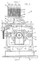
- the injection molding unit is axially displaceably mounted on stationary horizontal columns 15 and is supported on the rear on the machine base 42 via rollers 41, support columns 40 and a support pallet 39.
- the axially anchored columns 15 at the front end in the stationary mold carrier of the mold clamping unit and also supported on the machine base via a U-shaped bracket 17 (FIGS. 1, 2).
- the injection molding unit can be placed or set down on an injection mold accommodated in the mold clamping unit with the aid of two hydraulic travel cylinders F.
- the pistons 46 of the travel cylinder F are firmly seated on the columns 15 and are therefore stationary.
- the plasticizing cylinder 13 is received in a central bore of a supply block 20.
- the plastic material is supplied from a storage container arranged outside the injection molding unit to the plasticizing cylinder 13 by means of an air flow via supply lines 11, which can be connected to a chute 12 of this distributor block 20.
- the supply block 20 is penetrated by the columns 15 and forms a support bridge, so to speak. The same applies to a rear support piece 70.
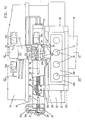
- the supply block 20, the support piece 70 and the hydraulic cylinders (injection cylinders 57, 58 and drive cylinder F) arranged between the aforementioned support bridges form a structural unit, as already described in DE-OS 3447 597.4- 16 disclosed.
- the piston 58 of the injection cylinder 57, 58 and its piston rod 58a are penetrated by a spindle 64, which on the back encloses the drive shaft 63b of the rotary drive 63 of the screw conveyor 14 in a rotationally fixed manner.
- the rotary drive 63 is fastened to the hollow piston rod 58a by means of contact flange 63a via a connecting flange 71. Thanks to its flange 64a and the thrust bearing 65, 66, the spindle 64 can rotate with respect to the non-rotatable piston 58, but is axially driven by this piston 58 during the axial injection stroke.
- a coupling part 35 which engages over the rear end of the screw conveyor for the purpose of coupling.
- the aforementioned structural unit (FIG. 3) is enclosed by a protective cover 21 of rectangular cross-section, the lower, horizontal wall of which forms raceways for the rollers 41 of second support columns 40 along the bending edges.
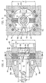
- the plasticizing cylinder 13 can be locked with the supply block 20 by means of bolts 49, 50.
- the bolts 49, 50 are guided radially in the supply block and can be controlled from a rear initial position into a bolt position. In the locking position, the locking bars 49 engage in a groove 13c in the plasticizing cylinder 13.
- the central bore passing through the supply block 20 and receiving the plasticizing cylinder 13 has a rear section of larger clear width (FIG. 3).
- the plasticizing cylinder 13 projects axially into this section.
- the locks 49 which can be steered into the annular groove 13c are guided on a radial annular shoulder 20d which is formed at the transition of the mentioned bore to its section of greater clear width.
- a bearing ring 51 dips into the rear of the bore of the supply block 20 in a form-fitting manner.
- the bearing ring 51 is axially supported on the radial ring shoulder 20d of the supply block 20 via end faces 51a.
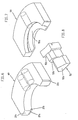
- Diametrical guideways for the bolts 49, 50 are recessed in the bearing ring 51, which guideways are delimited by guiding surfaces 51b (FIG. 9).
- the oblique surfaces 50a of the latches 50 which preload the plasticizing cylinder 13 are guided between abutment surfaces 51c of the bearing ring 51 and the latches 48.
- the inclined surfaces 50a of the latch 50 engage the rear, beveled end surface 13e of the plasticizing cylinder 13. In the axially pretensioned state, this is axially pressed onto the bolt 49 with the rear flank 13d of its groove 13c.
- the bolts 49 and 50 each arranged diametrically, can be moved into their starting position by means of radially guided wedges 52a, 52b of an unlocking body 52.
- these wedges 52a, 52b which can be controlled between the diametrical bolts 49 and 50, are arranged spatially in the unlocking body 52 such that the wedge 52b for the axially prestressing bolts 50 precedes the wedge 52a for the bolts 49 engaging in the groove 13c.
- the unlocking body 52 can be driven by the hydraulic cylinder 59, which is arranged radially in the supply block 20, via hydraulic Conclusions 60, 60a is supplied with pressure medium (Fig. 3).
- the supply block 20 is provided on the chute 12 with a plastic changing device W, by means of which a plurality of supply lines 11 can alternatively be connected to the chute 12.
- the plastic changing device W comprises a horizontal running rail 32 which extends symmetrically on both sides of the chute 12 and which is fastened on a horizontal connecting surface of an upper extension 20b of the supply block 20.
- a slide 33 with its motorized drive device can be displaced on the running rail 32.
- the carriage 33 engages behind the running rail 32 with engagement lugs 33a, 33b, as can be seen in particular from FIGS. 10 and 12.
- a connector 34 for the supply lines 11 is firmly seated.
- the motor drive device comprises an axially fixed threaded spindle 26 which can be rotated by means of a hydraulic rotary drive 37.
- a ball nut 27 On the threaded spindle 26 sits a ball nut 27, which is in engagement with the threads of the threaded spindle by means of its balls and is therefore moved axially when the threaded spindle 26 rotates.
- the ball nut sits in a receiving flange 33c of the slide 33 and therefore drives it during its axial movement.
- a bearing piece 22 is centered on the supply block 22 with an anchoring part 22a clamped between the running rail 32 and the shoulder 20b of the supply block 22. Both the running rail 32 and the extension 20b are positively engaged behind by an extension 22c on the side opposite the bearing part 22, as can be seen in particular from FIG. 11.
- a distributor block 23 is also attached, which distributes the pressure medium coming from the pressure pump via the line P and can be returned via the line T to the tank for the rotary drive 37 and for a hydraulic cylinder which serves to control slides 36 of the plastic changing device W. .
- the switching valves 24, 25 with electrical connections 24a, 25a are arranged on opposite, parallel sides of the distributor block 23, as can be seen in particular from FIGS. 10, 11.
- the hydraulic rotary drive 37 can be controlled by the switching valves 24 and the slide cylinder (piston 23c) can be controlled by the switching valves 24.
- a connecting pin 26a of the threaded spindle 26 is connected in a rotationally fixed manner with the aid of a driver 26b to a coupling piece 38, which sits in a rotationally fixed manner on a drive spindle 37a of the rotary drive 37 (FIG. 10).
- the connecting pin 26a is axially fixed in the bearing piece 22 by means of a combined axial-radial thrust bearing 28.
- the threaded spindle 26 is rotatably mounted in a housing 31 which is connected to the bearing part 22 in a load-bearing manner by means of diametrical rods 76.
- the protective cover 74 rests on the end face of the bearing piece 22 and the housing 31.
- a sensor disk 29, which is seated on the threaded spindle 26 in the housing 31, forms a pulse generator with a sensor 29a, which supplies the control pulses for the drive device of the slide 33 as a function of the rotation of the threaded spindle 26 for the computer of the injection molding machine.
- the housing 31, which is open at the top, is covered by a cover 31a which holds the sensor 29a.
- the supply lines 11 can be plugged into connecting bores 34b of the connecting piece 34 by means of plug-in sleeves 54 and can be locked with the aid of the locking elements 34d.
- the supply line 11 with the desired plastic can be brought into a position in which the fall hole 34c of the connection piece 34 associated with this supply line 11, the fall hole 36b of the associated one, between the connection piece 34 and the running rail 32 arranged locking slide 36, the drop hole 32a of the running rail 32 and the drop hole 22b of the anchoring flange 22a are identical to the drop shaft 12.
- a blocking slide 36b is assigned, which can be moved transversely to the direction of travel of the slide 33 into a position in which it blocks the fall hole 34c and thus the supply of the plastic material.
- All locking slides 36 of the plastic changing device W can be controlled by a single hydraulic cylinder, referred to as a slide cylinder, with a piston 23c and a piston rod 23d (FIG. 11).
- the cylinder of this slide cylinder is formed by a bore in the distributor block 23, which is closed off by a cylinder cover 23a with sealing rings 23b.
- the blocking slide 36 which controls the drop hole 34c, which is congruent with the drop shaft 12, can be coupled to the piston rod 23d of the slide cylinder by means of a coupling rib 36a.
- a horizontal coupling rib 36a engages in a corresponding recess in this piston rod.
- the coupling rib 36a automatically comes out of its coupling position.
- the coupling rib 36a of the locking slide 36 which is now in the working position, is moved into the coupling position by moving into the corresponding recess in the piston rod 23d.
- the supply lines 11 can be fed from storage containers which are arranged outside the injection molding unit, expediently above the same.
- Air flow transport line can be controlled by means of a metering device 10.
- a metering device 10 This includes a known (DE-PS 24 09 128) screen head 10c. This regulates the air flow depending on its filling level.
- the plasticizing cylinder 13 is secured against rotation by means of a bolt 73, the free end of which protrudes between the prestressing slides 50.
- An approximately cuboidal unlocking part 52c of the unlocking body 52 controls the coupling device for the screw conveyor 14.
- the unlocking body 52 is operatively connected via an actuating element 62 to a control switch 61 which is attached to the supply block 20.
- the supply block 20 can be axially removed from the plasticizing cylinder 13 by means of a corresponding backward stroke (release stroke) with the remaining injection molding unit, so that the latter is free for removal of the plasticizing unit is.
- the plasticizing cylinder 13 which is enclosed by a cover 18 of square cross-section, can be locked by means of a hydraulic cylinder (not shown in the drawing) which engages on this cover 18 for axially fixing the plasticizing unit.
- a change of the plasticizing unit with a simultaneous change of the plastic material can be achieved according to the program by the following steps:
- the injection molding unit is removed from the injection mold by a corresponding return stroke of the drive cylinder F.
- the bars 49, 50 are then pressed out of their locking position by a radial stroke of the unlocking body 52 and, at the same time, the plasticizing unit is axially locked.
- the plasticizing unit is then separated from the remaining injection molding unit by a release stroke of the driving cylinders F from the plasticizing cylinder 13 of the plasticizing unit. After the release stroke, the plasticizing unit lies on the horizontal horizontal wall of its cover 18 on a horizontal web 17a of the support bracket 17 and is centered there with the aid of the stiffening ribs 17e.
- the plasticizing unit is free for removal upwards.
- the desired new plasticizing unit is brought into the working position in the reverse order using the same process steps and locked with the supply block of the 'remaining injection molding unit'. Then, using the plastic changing device W, another supply line 11, via which the desired new plastic can be fed in, is brought into congruence with the fall hole 12 of the supply block 20 by a corresponding method of the slide 33.
- the support bracket 17, on which the plasticizing unit is supported after the release stroke, is fixed on the support pallet 39 via the feet 17d.
- the 'remaining injection molding unit' separated from the plasticizing unit is slidably supported on the front cylinder covers 16 and driving cylinder F and on their rear cylinder covers on the columns 15.
Landscapes
- Engineering & Computer Science (AREA)
- Manufacturing & Machinery (AREA)
- Mechanical Engineering (AREA)
- Injection Moulding Of Plastics Or The Like (AREA)
Claims (8)
Priority Applications (1)
| Application Number | Priority Date | Filing Date | Title |
|---|---|---|---|
| AT86105180T ATE53184T1 (de) | 1985-04-15 | 1986-04-15 | Spritzgiesseinheit fuer eine kunststoffspritzgiessmaschine. |
Applications Claiming Priority (6)
| Application Number | Priority Date | Filing Date | Title |
|---|---|---|---|
| DE3513411 | 1985-04-15 | ||
| DE19853513411 DE3513411A1 (de) | 1985-04-15 | 1985-04-15 | Kunststoff-spritzgiessmaschine |
| DE3526710 | 1985-07-26 | ||
| DE19853526710 DE3526710C1 (de) | 1985-04-15 | 1985-07-26 | Spritzgießeinheit mit Kupplungseinrichtung für den Plastifizierzylinder |
| DE3605219 | 1986-02-19 | ||
| DE19863605219 DE3605219A1 (de) | 1986-02-19 | 1986-02-19 | Spritzgiesseinheit fuer eine kunststoff-spritzgiessmaschine |
Publications (3)
| Publication Number | Publication Date |
|---|---|
| EP0200962A2 EP0200962A2 (fr) | 1986-11-12 |
| EP0200962A3 EP0200962A3 (en) | 1988-10-12 |
| EP0200962B1 true EP0200962B1 (fr) | 1990-05-30 |
Family
ID=27193011
Family Applications (1)
| Application Number | Title | Priority Date | Filing Date |
|---|---|---|---|
| EP86105180A Expired - Lifetime EP0200962B1 (fr) | 1985-04-15 | 1986-04-15 | Unité d'injection pour machine de moulage par injection de matière plastique |
Country Status (2)
| Country | Link |
|---|---|
| EP (1) | EP0200962B1 (fr) |
| DE (1) | DE3671610D1 (fr) |
Cited By (1)
| Publication number | Priority date | Publication date | Assignee | Title |
|---|---|---|---|---|
| DE102020112590B3 (de) * | 2020-05-08 | 2021-05-20 | Arburg Gmbh + Co Kg | Spritzgießeinheit für eine Spritzgießmaschine zur Verarbeitung von Kunststoffen |
Families Citing this family (5)
| Publication number | Priority date | Publication date | Assignee | Title |
|---|---|---|---|---|
| DE4216312C1 (de) * | 1992-05-16 | 1993-11-25 | Karl Hehl | Kunststoff-Wechseleinrichtung |
| CN107322311A (zh) * | 2017-08-14 | 2017-11-07 | 金勇� | 锁芯壳加工处理装置 |
| CN107336024A (zh) * | 2017-08-14 | 2017-11-10 | 金勇� | 锁芯壳处理加工装置 |
| CN112643318B (zh) * | 2020-09-21 | 2022-02-11 | 中山市哈工朗德智能科技有限公司 | 一种新型螺杆快拆装置 |
| CN117774221B (zh) * | 2023-09-05 | 2024-07-19 | 盐城立德塑业有限公司 | 一种洗衣机塑料盖板注塑装置 |
Family Cites Families (3)
| Publication number | Priority date | Publication date | Assignee | Title |
|---|---|---|---|---|
| FR1344247A (fr) * | 1962-04-27 | 1963-11-29 | Machine pour la fabrication automatique, par injection, d'objets en matière plastique | |
| CH653948A5 (de) * | 1981-09-28 | 1986-01-31 | Netstal Ag Maschf Giesserei | Kupplungsvorrichtung zwischen antriebsvorrichtung und schnecke der plastifiziereinheit einer spritzgiessmaschine. |
| EP0198364B1 (fr) * | 1985-04-15 | 1991-01-02 | Karl Hehl | Unité de moulage par injection de matière plastique |
-
1986
- 1986-04-15 DE DE8686105180T patent/DE3671610D1/de not_active Expired - Lifetime
- 1986-04-15 EP EP86105180A patent/EP0200962B1/fr not_active Expired - Lifetime
Cited By (2)
| Publication number | Priority date | Publication date | Assignee | Title |
|---|---|---|---|---|
| DE102020112590B3 (de) * | 2020-05-08 | 2021-05-20 | Arburg Gmbh + Co Kg | Spritzgießeinheit für eine Spritzgießmaschine zur Verarbeitung von Kunststoffen |
| WO2021224344A1 (fr) | 2020-05-08 | 2021-11-11 | Arburg Gmbh + Co Kg | Unité de moulage par injection pour une machine de moulage par injection pour la transformation de matières plastiques |
Also Published As
| Publication number | Publication date |
|---|---|
| EP0200962A3 (en) | 1988-10-12 |
| EP0200962A2 (fr) | 1986-11-12 |
| DE3671610D1 (de) | 1990-07-05 |
Similar Documents
| Publication | Publication Date | Title |
|---|---|---|
| EP2976160B1 (fr) | Système de pulvérisation, installation de revêtement et procédé de revêtement | |
| DE2421811C2 (de) | Formschließeinheit für eine Kunststoff-Spritzgießmaschine mit einem Schiebetisch | |
| CH663569A5 (de) | Beschickungseinrichtung zum zufuehren von kunststoffgranulat in eine spritzgiesseinheit. | |
| EP0143196A2 (fr) | Tête de mixeur pour la fabrication d'un mélange capable de produire une réaction chimique et consistant en au moins deux composants de plastique | |
| EP0301200B1 (fr) | Dispositif pour injecter des matières plastiques en remplissant le moule par voie centrale ou linéaire au choix | |
| EP0198364B1 (fr) | Unité de moulage par injection de matière plastique | |
| DE3046387C2 (de) | Spritzgießeinheit einer Kunststoff-Spritzgießmaschine mit einem Behälter für rieselfähiges Kunststoffmaterial | |
| EP0200962B1 (fr) | Unité d'injection pour machine de moulage par injection de matière plastique | |
| DE3722228C2 (fr) | ||
| DE3645163C2 (en) | Changing mould for injection moulding | |
| EP0202433A2 (fr) | Dispositif d'accouplement sur une unité de travail interchangeable d'une machine de moulage par injection de matière plastique | |
| DE3742403C1 (de) | Plastifizieraggregat mit Armierungsskelett fuer eine Kunststoff-Spritzgiesseinheit | |
| DE4314941C2 (de) | Spritzeinheit an Spritzgießmaschinen zur Herstellung thermoplastischer Kunststoffteile | |
| DE3605219C2 (fr) | ||
| DE3708434C2 (fr) | ||
| DE4227336C1 (de) | Kunststoff-Spritzgießmaschine | |
| DE69114163T2 (de) | Handhabung eines Mehrkomponentenklebers. | |
| DE3513411C2 (fr) | ||
| CH644788A5 (de) | An der formschliesseinheit einer kunststoffspritzgiessmaschine befestigte spritzgiesseinheit. | |
| DE3637166C2 (fr) | ||
| DE69020936T2 (de) | Reaktionsspritzgussmaschine mit Verwendung mehrerer Reaktionsflüssigkeiten. | |
| DE19536567A1 (de) | Formschließeinheit mit einer Einrichtung zur Behandlung und/oder Entfernung von Spritzteilen | |
| EP0204133A1 (fr) | Procédé pour fabriquer des objets en matière thermoplastique par moulage par injection | |
| EP0394790B1 (fr) | Dispositif pour la fabrication d'un mélange réactif apte à couler à partir d'au moins deux composants réactifs aptes à couler pour la fabrication de matières plastiques massives ou cellulaires | |
| DE3828061C1 (fr) |
Legal Events
| Date | Code | Title | Description |
|---|---|---|---|
| PUAI | Public reference made under article 153(3) epc to a published international application that has entered the european phase |
Free format text: ORIGINAL CODE: 0009012 |
|
| AK | Designated contracting states |
Kind code of ref document: A2 Designated state(s): AT CH DE FR GB IT LI NL |
|
| XX | Miscellaneous (additional remarks) |
Free format text: EIN ANTRAG GEMAESS REGEL 88 EPUE AUF BERICHTIGUNG DER BESCHREIBUNG, S.2, LIEGT VOR.UEBER DIESEN ANTRAG WIRD IM LAUFE DES VERFAHRENS VON DER PRUEFUNGSABTEILUNG EINE ENTSCHEIDUNG GETROFFEN WERDEN. |
|
| PUAL | Search report despatched |
Free format text: ORIGINAL CODE: 0009013 |
|
| RHK1 | Main classification (correction) |
Ipc: B29C 45/17 |
|
| AK | Designated contracting states |
Kind code of ref document: A3 Designated state(s): AT CH DE FR GB IT LI NL |
|
| 17P | Request for examination filed |
Effective date: 19890317 |
|
| 17Q | First examination report despatched |
Effective date: 19890629 |
|
| GRAA | (expected) grant |
Free format text: ORIGINAL CODE: 0009210 |
|
| AK | Designated contracting states |
Kind code of ref document: B1 Designated state(s): AT CH DE FR GB IT LI NL |
|
| REF | Corresponds to: |
Ref document number: 53184 Country of ref document: AT Date of ref document: 19900615 Kind code of ref document: T |
|
| GBT | Gb: translation of ep patent filed (gb section 77(6)(a)/1977) | ||
| REF | Corresponds to: |
Ref document number: 3671610 Country of ref document: DE Date of ref document: 19900705 |
|
| ITF | It: translation for a ep patent filed | ||
| ET | Fr: translation filed | ||
| PLBE | No opposition filed within time limit |
Free format text: ORIGINAL CODE: 0009261 |
|
| STAA | Information on the status of an ep patent application or granted ep patent |
Free format text: STATUS: NO OPPOSITION FILED WITHIN TIME LIMIT |
|
| ITTA | It: last paid annual fee | ||
| 26N | No opposition filed | ||
| PGFP | Annual fee paid to national office [announced via postgrant information from national office to epo] |
Ref country code: DE Payment date: 19930318 Year of fee payment: 8 |
|
| PGFP | Annual fee paid to national office [announced via postgrant information from national office to epo] |
Ref country code: GB Payment date: 19930324 Year of fee payment: 8 |
|
| PGFP | Annual fee paid to national office [announced via postgrant information from national office to epo] |
Ref country code: FR Payment date: 19930417 Year of fee payment: 8 |
|
| PGFP | Annual fee paid to national office [announced via postgrant information from national office to epo] |
Ref country code: AT Payment date: 19930422 Year of fee payment: 8 |
|
| PGFP | Annual fee paid to national office [announced via postgrant information from national office to epo] |
Ref country code: NL Payment date: 19930430 Year of fee payment: 8 |
|
| PGFP | Annual fee paid to national office [announced via postgrant information from national office to epo] |
Ref country code: CH Payment date: 19930519 Year of fee payment: 8 |
|
| PG25 | Lapsed in a contracting state [announced via postgrant information from national office to epo] |
Ref country code: GB Effective date: 19940415 Ref country code: AT Effective date: 19940415 |
|
| PG25 | Lapsed in a contracting state [announced via postgrant information from national office to epo] |
Ref country code: LI Effective date: 19940430 Ref country code: CH Effective date: 19940430 |
|
| PG25 | Lapsed in a contracting state [announced via postgrant information from national office to epo] |
Ref country code: NL Effective date: 19941101 |
|
| GBPC | Gb: european patent ceased through non-payment of renewal fee |
Effective date: 19940415 |
|
| NLV4 | Nl: lapsed or anulled due to non-payment of the annual fee | ||
| PG25 | Lapsed in a contracting state [announced via postgrant information from national office to epo] |
Ref country code: FR Effective date: 19941229 |
|
| REG | Reference to a national code |
Ref country code: CH Ref legal event code: PL |
|
| PG25 | Lapsed in a contracting state [announced via postgrant information from national office to epo] |
Ref country code: DE Effective date: 19950103 |
|
| REG | Reference to a national code |
Ref country code: FR Ref legal event code: ST |
|
| PG25 | Lapsed in a contracting state [announced via postgrant information from national office to epo] |
Ref country code: IT Free format text: LAPSE BECAUSE OF NON-PAYMENT OF DUE FEES;WARNING: LAPSES OF ITALIAN PATENTS WITH EFFECTIVE DATE BEFORE 2007 MAY HAVE OCCURRED AT ANY TIME BEFORE 2007. THE CORRECT EFFECTIVE DATE MAY BE DIFFERENT FROM THE ONE RECORDED. Effective date: 20050415 |