EP0200979A2 - Machine à cintrer des tubes - Google Patents
Machine à cintrer des tubes Download PDFInfo
- Publication number
- EP0200979A2 EP0200979A2 EP86105500A EP86105500A EP0200979A2 EP 0200979 A2 EP0200979 A2 EP 0200979A2 EP 86105500 A EP86105500 A EP 86105500A EP 86105500 A EP86105500 A EP 86105500A EP 0200979 A2 EP0200979 A2 EP 0200979A2
- Authority
- EP
- European Patent Office
- Prior art keywords
- clamping
- bending
- clamping jaw
- bending template
- template
- Prior art date
- Legal status (The legal status is an assumption and is not a legal conclusion. Google has not performed a legal analysis and makes no representation as to the accuracy of the status listed.)
- Granted
Links
Images

Classifications
-
- B—PERFORMING OPERATIONS; TRANSPORTING
- B21—MECHANICAL METAL-WORKING WITHOUT ESSENTIALLY REMOVING MATERIAL; PUNCHING METAL
- B21D—WORKING OR PROCESSING OF SHEET METAL OR METAL TUBES, RODS OR PROFILES WITHOUT ESSENTIALLY REMOVING MATERIAL; PUNCHING METAL
- B21D7/00—Bending rods, profiles, or tubes
- B21D7/02—Bending rods, profiles, or tubes over a stationary forming member; by use of a swinging forming member or abutment
- B21D7/024—Bending rods, profiles, or tubes over a stationary forming member; by use of a swinging forming member or abutment by a swinging forming member
-
- B—PERFORMING OPERATIONS; TRANSPORTING
- B21—MECHANICAL METAL-WORKING WITHOUT ESSENTIALLY REMOVING MATERIAL; PUNCHING METAL
- B21D—WORKING OR PROCESSING OF SHEET METAL OR METAL TUBES, RODS OR PROFILES WITHOUT ESSENTIALLY REMOVING MATERIAL; PUNCHING METAL
- B21D7/00—Bending rods, profiles, or tubes
- B21D7/02—Bending rods, profiles, or tubes over a stationary forming member; by use of a swinging forming member or abutment
- B21D7/021—Construction of forming members having more than one groove
Definitions
- the invention relates to a pipe bending machine with the features of the preamble of claim 1.
- a contact surface in particular a recess for exchangeably accommodating a clamping body provided with the clamping surface, is provided on the bending template and the clamping jaw, and each clamping body is arranged on a guide and provided with a hydraulic drive, which moves the clamping body with a vertical movement in the recess so that one or the other clamping surface of the plurality of different clamping surfaces of the clamping body arranged one above the other enters the plane of the groove of the bending template.
- the present invention is based on the task of arranging and moving the clamping bodies on the bending template and on the clamping jaw in such a way that their rapid change is possible and the clamping surfaces that are not in operation when the tube is inserted into the tube bending machine or during bending to disturb.
- the proposal to arrange the cylinder space for the drive of the clamping body of the bending template within the bending template and to arrange the cylinder space for the clamping body of the clamping jaw within the clamping jaw means that the hydraulic drive protrudes only a small amount above the top of the bending template or clamping jaw and therefore no or only insignificant hindrance can occur when inserting the tube or when bending.
- the clamping bodies are connected to the associated piston rod via a cantilever.
- the bending template is comparatively flat, then part of the cylinder can protrude above the top. It is also possible for a part of the cylinder to protrude downward over the underside of the bending template into the bending table. In any case, the invention provides that the overall height of the bending template and / or the clamping jaw is used to accommodate or partially accommodate the hydraulic cylinder.
- the clamping jaw can be rotated in a manner known per se about a horizontal axis and has two flat surfaces which are adjacent to one another, preferably at a right angle, and on one of the two surfaces or on both surfaces of the clamping body provided with several different clamping surfaces is slidably mounted. This measure makes it possible in a simple manner to arrange clamping surfaces of different designs in a comparatively narrow space and to bring them into effect quickly.
- Another proposal is that there are three different clamping surfaces on top of one another on the clamping body arranged on the bending template and two different clamping surfaces arranged one behind the other and one above the other in the working position on the clamping jaw assigned to the clamping jaw.
- FIG. 1 shows a conventional pipe bending machine with a feed carriage 10, which can slide back and forth on one or more guide rails 11 on the top of the machine housing 12.
- the feed carriage 10 has a hollow cylinder 13, in the interior of which there is a clamping sleeve 14, in which the end region of the pipe section or pipe 15 to be bent is clamped.
- the pipe section 15 is guided around a pivotably mounted bending template 16, which has a groove 17 for the pipe which corresponds to the pipe radius.
- a clamping jaw 19 is pressed by means of a clamping device 18, which also has a groove corresponding to the pipe radius as clamping surface and clamps the pipe 15 on the bending template 16.
- a hydraulic cylinder 20 is shown as an example, which moves the clamping device 18 of the clamping jaw 19 towards the bending template 16 for clamping the tube or removes it from this template.
- the bending template 16 is fixedly arranged on the bending table 21, while the clamping device 18 can be pushed back and forth in the indicated arrow direction 22 via the cylinder 20 shown as an example. If the bending template 16 is pivoted over the bending table 21 together with the clamping jaw 19 in the direction of the arrow 23, the pipe section 15 is given a curvature which corresponds to the profile of the bending template 16. During this bending process, the end part of the pipe section 15 remains clamped in the clamping sleeve 14 of the feed carriage 10 in order to safely guide the pipe section in all positions.
- a slide rail 24 is pressed onto this pipe section part, which also has a groove which corresponds to the pipe radius.
- the clamping sleeve 14 of the feed carriage 10 not only clamps the pipe section 15 firmly, but also turns it by amounts up to 360 ° if successive pipe bends are to be bent in different directions.
- a hydraulic motor rotates a worm which interacts with a worm wheel (not shown) which is connected to the clamping sleeve 14.
- FIG. 2 shows an exhaust pipe which can be produced with the bending machine and in which curved sections or pipe bends S 1 and S 2 as well as S 3 and S 4 are directly connected. There are also linear intermediate lengths L 1, L 2 and L 3, which, however, do not need to be present except for the length L 1.
- FIG. 2 thus shows a tube in which there are partially straight intermediate lengths between bends and partially straight intermediate lengths between bends do not exist.
- This tube shown in Figure 2 can be bent with a single relaxation on the tube bending machine. Such a machine is shown as an example in FIG. 3.
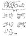
- FIG. 3 shows that the cylinder space or cylinder 25 of the hydraulic drive, which has a piston 26 with a piston rod 27, is arranged within the bending template.
- a right-angled outrigger 28 At the upper end of the piston rod there is a right-angled outrigger 28, on which a clamping element 30 is arranged via a fastening element 29, which has differently designed clamping surfaces 31 and 32 at two different heights.
- the bending template has the bending groove 33.
- the opposing clamping jaw 19 also has a cylinder 25a with a piston and piston rod of the design described above, so that the clamping body 30a with the associated clamping surfaces 31a and 32a arranged one above the other can be used in different operating positions.
- the jaw body 19 is additionally rotatable about the horizontal axis 34, specifically via a hydraulic motor 35 which is provided with a boom 36 which is articulated on a rod 37 which is fastened to the axis 38 of the clamping jaw 19 .
- the clamping jaw has two flat surfaces 39 and 40 adjacent at a right angle, the clamping body 30a with the different clamping surfaces 31a and 32a being slidably mounted on the surface 40, while a stationary clamping body 41 is arranged on the surface 39.
- Figures 4 to 8 show different positions of the clamping body 30 to the opposite clamping body 30a or depending on the rotation of the clamping jaw to the opposite individual clamping body 41.
- Figure 8 shows that a clamping body 30 is arranged on the bending template 16, which has three clamping surfaces arranged one above the other of different dimensions or design.
- Clamping bodies 30a and 41a are present on the clamping jaw 19, which can be displaced on the assigned surfaces via a hydraulic drive and each have two different clamping surfaces.
Landscapes
- Engineering & Computer Science (AREA)
- Mechanical Engineering (AREA)
- Bending Of Plates, Rods, And Pipes (AREA)
Applications Claiming Priority (2)
| Application Number | Priority Date | Filing Date | Title |
|---|---|---|---|
| DE3516923 | 1985-05-10 | ||
| DE19853516923 DE3516923A1 (de) | 1985-05-10 | 1985-05-10 | Rohrbiegemaschine |
Publications (3)
| Publication Number | Publication Date |
|---|---|
| EP0200979A2 true EP0200979A2 (fr) | 1986-11-12 |
| EP0200979A3 EP0200979A3 (en) | 1987-01-07 |
| EP0200979B1 EP0200979B1 (fr) | 1989-11-15 |
Family
ID=6270419
Family Applications (1)
| Application Number | Title | Priority Date | Filing Date |
|---|---|---|---|
| EP86105500A Expired EP0200979B1 (fr) | 1985-05-10 | 1986-04-21 | Machine à cintrer des tubes |
Country Status (3)
| Country | Link |
|---|---|
| US (1) | US4821549A (fr) |
| EP (1) | EP0200979B1 (fr) |
| DE (2) | DE3516923A1 (fr) |
Cited By (4)
| Publication number | Priority date | Publication date | Assignee | Title |
|---|---|---|---|---|
| EP0245623A3 (en) * | 1986-05-14 | 1990-03-28 | Rigobert Dipl.-Ing. Schwarze | Tube-bending machine |
| EP0364836A3 (fr) * | 1988-10-15 | 1990-11-28 | Günther-F. Pulzer | Procédé et dispositif pour cintrer des pièces à usiner en barres |
| EP2289643A3 (fr) * | 2009-08-24 | 2011-10-05 | Tracto-Technik GmbH & CO. KG | Dispositif pour le pliage de longues pièces usinées |
| US9849494B2 (en) | 2013-11-15 | 2017-12-26 | Textron Innovations Inc. | Automated bender and systems and methods for providing data to operate an automated bender |
Families Citing this family (6)
| Publication number | Priority date | Publication date | Assignee | Title |
|---|---|---|---|---|
| DE4442030A1 (de) * | 1994-11-25 | 1996-05-30 | Sen Bernhard Kreye | Verfahren zum Biegen von Metallprofilen, vorzugsweise Metallprofilen, die als Sprossen für Fenster und Türen verwendet werden, und Planscheibenbiegemaschine zur Durchführung des Verfahrens |
| DE19530805A1 (de) * | 1995-08-22 | 1997-02-27 | Schwarze Rigobert | CNC-gesteuerte Rohrbiegemaschine |
| DE19630163C1 (de) * | 1996-07-26 | 1997-12-11 | Schmitz & Brill Gmbh & Co Kg | Biegevorrichtung |
| CN101934314B (zh) * | 2010-07-19 | 2012-04-04 | 江苏合丰机械制造有限公司 | 弯管机中能左右弯的弯管装置 |
| CN109175036A (zh) * | 2018-08-28 | 2019-01-11 | 四川凯润电器有限公司 | 一种热交换管弯折装置 |
| CN119819768B (zh) * | 2025-03-13 | 2025-06-20 | 江苏精达制管有限公司 | 一种不锈钢管折弯加工辅助装置 |
Family Cites Families (11)
| Publication number | Priority date | Publication date | Assignee | Title |
|---|---|---|---|---|
| DE25279C (de) * | W. NUSSBECK in Berlin, Neuer Markt 8 | Bierkühlapparat | ||
| DE120336C (fr) * | ||||
| DE1087431B (de) * | 1959-05-29 | 1960-08-18 | Hilgers Maschinen Und App Baua | Selbsttaetige Ausschiebeeinrichtung fuer eine Rohrbiegemaschine |
| US3299681A (en) * | 1960-03-22 | 1967-01-24 | Baldwin Lima Hamilton Corp | Program controlled tube bender |
| US3147792A (en) * | 1961-09-25 | 1964-09-08 | Charles F Hautau | Tube and bar bending machinery |
| DE2626202C2 (de) * | 1976-06-11 | 1992-10-29 | Rigobert Dipl.-Ing. 5000 Köln Schwarze | Rohrbiegemaschine |
| US4238398A (en) * | 1979-10-31 | 1980-12-09 | The Upjohn Company | Antibiotics 7(R)-O-alkylnogalarols |
| DE3033300A1 (de) * | 1980-09-04 | 1982-04-01 | Rigobert Dipl.-Ing. 5000 Köln Schwarze | Rohrbiegemaschine |
| US4495788A (en) * | 1982-08-02 | 1985-01-29 | Eaton-Leonard Corporation | Multiple curvature bender |
| EP0120336B2 (fr) * | 1983-03-26 | 1991-10-09 | Rigobert Dipl.-Ing. Schwarze | Machine à cintrer les tubes |
| JPS59178131A (ja) * | 1983-03-28 | 1984-10-09 | Suzuki Motor Co Ltd | 曲げ装置 |
-
1985
- 1985-05-10 DE DE19853516923 patent/DE3516923A1/de not_active Withdrawn
-
1986
- 1986-04-21 DE DE8686105500T patent/DE3666923D1/de not_active Expired
- 1986-04-21 EP EP86105500A patent/EP0200979B1/fr not_active Expired
-
1988
- 1988-01-13 US US07/143,617 patent/US4821549A/en not_active Expired - Lifetime
Cited By (7)
| Publication number | Priority date | Publication date | Assignee | Title |
|---|---|---|---|---|
| EP0245623A3 (en) * | 1986-05-14 | 1990-03-28 | Rigobert Dipl.-Ing. Schwarze | Tube-bending machine |
| EP0364836A3 (fr) * | 1988-10-15 | 1990-11-28 | Günther-F. Pulzer | Procédé et dispositif pour cintrer des pièces à usiner en barres |
| EP2289643A3 (fr) * | 2009-08-24 | 2011-10-05 | Tracto-Technik GmbH & CO. KG | Dispositif pour le pliage de longues pièces usinées |
| US9849494B2 (en) | 2013-11-15 | 2017-12-26 | Textron Innovations Inc. | Automated bender and systems and methods for providing data to operate an automated bender |
| EP3068556A4 (fr) * | 2013-11-15 | 2018-02-14 | Textron Innovations Inc. | Fourniture de données pour fonctionnement de cintreuse automatisée |
| US10406580B2 (en) | 2013-11-15 | 2019-09-10 | Greenlee Tools, Inc. | Automated bender and systems and methods for providing data to operate an automated bender |
| US10792718B2 (en) | 2013-11-15 | 2020-10-06 | Greenlee Tools, Inc. | Follower bar assembly for a bender |
Also Published As
| Publication number | Publication date |
|---|---|
| EP0200979A3 (en) | 1987-01-07 |
| US4821549A (en) | 1989-04-18 |
| EP0200979B1 (fr) | 1989-11-15 |
| DE3666923D1 (en) | 1989-12-21 |
| DE3516923A1 (de) | 1986-11-13 |
Similar Documents
| Publication | Publication Date | Title |
|---|---|---|
| DE3601231C2 (fr) | ||
| EP0245623B1 (fr) | Machine à plier des tubes | |
| DE3922326C2 (fr) | ||
| EP0108193B1 (fr) | Presse à courber des tubes | |
| DE3033300C2 (fr) | ||
| DE2626202A1 (de) | Rohrbiegemaschine | |
| DE4335901A1 (de) | Doppelkopf-Rohrbiegemaschine | |
| EP0649687B1 (fr) | Machine à cintrer les tubes | |
| EP0200979B1 (fr) | Machine à cintrer des tubes | |
| DE68904694T2 (de) | Spannmechanismus eines geraetes zum bohren oder senken von loechern in einem werkstueck. | |
| DE3627502C2 (de) | Rohrbiegemaschine | |
| EP0120336B2 (fr) | Machine à cintrer les tubes | |
| DE3045791C2 (fr) | ||
| DE3831378C2 (de) | Anschlagvorrichtung für Tischsägen | |
| DE3619677C1 (de) | Vorrichtung zum Heben und Senken des Kopf- und des Fussteiles eines Bettrahmens | |
| DE69800606T2 (de) | Biegevorrichtung | |
| DE2063041C3 (de) | Einrichtung zum Biegen von Stäben u.dgl | |
| DE3625074C2 (fr) | ||
| DE3033950C2 (de) | Rohrbiegemaschine | |
| DE10229652B4 (de) | Schlitten für Rohrbiegemaschine | |
| DE2917670C2 (de) | Schreitfähige Hubinsel | |
| AT361760B (de) | Vorrichtung und verfahren zum herstellen eines spannbuegels zur befestigung von eisenbahn- schienen | |
| DE19607968A1 (de) | Behandlungsliege | |
| DE4439412A1 (de) | Vorrichtung und Verfahren zum Vertauschen der Stellungen zweier Arbeitstische, insbesondere zweier Werkstückträger für den Zusammenbau von aus gestanzten Blechteilen zu fertigenden Baugruppen | |
| EP0604747A1 (fr) | Machine à plier |
Legal Events
| Date | Code | Title | Description |
|---|---|---|---|
| PUAI | Public reference made under article 153(3) epc to a published international application that has entered the european phase |
Free format text: ORIGINAL CODE: 0009012 |
|
| AK | Designated contracting states |
Kind code of ref document: A2 Designated state(s): DE FR GB IT SE |
|
| PUAL | Search report despatched |
Free format text: ORIGINAL CODE: 0009013 |
|
| AK | Designated contracting states |
Kind code of ref document: A3 Designated state(s): DE FR GB IT SE |
|
| 17P | Request for examination filed |
Effective date: 19870124 |
|
| 17Q | First examination report despatched |
Effective date: 19880708 |
|
| GRAA | (expected) grant |
Free format text: ORIGINAL CODE: 0009210 |
|
| AK | Designated contracting states |
Kind code of ref document: B1 Designated state(s): DE FR GB IT SE |
|
| ITF | It: translation for a ep patent filed | ||
| GBT | Gb: translation of ep patent filed (gb section 77(6)(a)/1977) | ||
| ET | Fr: translation filed | ||
| REF | Corresponds to: |
Ref document number: 3666923 Country of ref document: DE Date of ref document: 19891221 |
|
| PLBI | Opposition filed |
Free format text: ORIGINAL CODE: 0009260 |
|
| 26 | Opposition filed |
Opponent name: LANG MASCHINENBAU GMBH U. CO. KG Effective date: 19900816 |
|
| ITTA | It: last paid annual fee | ||
| PLBM | Termination of opposition procedure: date of legal effect published |
Free format text: ORIGINAL CODE: 0009276 |
|
| STAA | Information on the status of an ep patent application or granted ep patent |
Free format text: STATUS: OPPOSITION PROCEDURE CLOSED |
|
| 27C | Opposition proceedings terminated |
Effective date: 19910211 |
|
| EAL | Se: european patent in force in sweden |
Ref document number: 86105500.2 |
|
| REG | Reference to a national code |
Ref country code: GB Ref legal event code: IF02 |
|
| PGFP | Annual fee paid to national office [announced via postgrant information from national office to epo] |
Ref country code: GB Payment date: 20050412 Year of fee payment: 20 |
|
| PGFP | Annual fee paid to national office [announced via postgrant information from national office to epo] |
Ref country code: FR Payment date: 20050419 Year of fee payment: 20 |
|
| PGFP | Annual fee paid to national office [announced via postgrant information from national office to epo] |
Ref country code: SE Payment date: 20050422 Year of fee payment: 20 |
|
| PGFP | Annual fee paid to national office [announced via postgrant information from national office to epo] |
Ref country code: IT Payment date: 20050427 Year of fee payment: 20 |
|
| PGFP | Annual fee paid to national office [announced via postgrant information from national office to epo] |
Ref country code: DE Payment date: 20050524 Year of fee payment: 20 |
|
| PG25 | Lapsed in a contracting state [announced via postgrant information from national office to epo] |
Ref country code: GB Free format text: LAPSE BECAUSE OF EXPIRATION OF PROTECTION Effective date: 20060420 |
|
| REG | Reference to a national code |
Ref country code: GB Ref legal event code: PE20 |
|
| EUG | Se: european patent has lapsed |