EP0200987A1 - Appareil de radiologie comportant un système d'équilibrage à ressort - Google Patents
Appareil de radiologie comportant un système d'équilibrage à ressort Download PDFInfo
- Publication number
- EP0200987A1 EP0200987A1 EP86105540A EP86105540A EP0200987A1 EP 0200987 A1 EP0200987 A1 EP 0200987A1 EP 86105540 A EP86105540 A EP 86105540A EP 86105540 A EP86105540 A EP 86105540A EP 0200987 A1 EP0200987 A1 EP 0200987A1
- Authority
- EP
- European Patent Office
- Prior art keywords
- motor
- carriage
- threaded spindle
- load lever
- ray
- Prior art date
- Legal status (The legal status is an assumption and is not a legal conclusion. Google has not performed a legal analysis and makes no representation as to the accuracy of the status listed.)
- Granted
Links
Images
Classifications
-
- A—HUMAN NECESSITIES
- A61—MEDICAL OR VETERINARY SCIENCE; HYGIENE
- A61B—DIAGNOSIS; SURGERY; IDENTIFICATION
- A61B6/00—Apparatus or devices for radiation diagnosis; Apparatus or devices for radiation diagnosis combined with radiation therapy equipment
- A61B6/04—Positioning of patients; Tiltable beds or the like
- A61B6/0487—Motor-assisted positioning
-
- A—HUMAN NECESSITIES
- A61—MEDICAL OR VETERINARY SCIENCE; HYGIENE
- A61B—DIAGNOSIS; SURGERY; IDENTIFICATION
- A61B6/00—Apparatus or devices for radiation diagnosis; Apparatus or devices for radiation diagnosis combined with radiation therapy equipment
- A61B6/44—Constructional features of apparatus for radiation diagnosis
- A61B6/4429—Constructional features of apparatus for radiation diagnosis related to the mounting of source units and detector units
- A61B6/447—Constructional features of apparatus for radiation diagnosis related to the mounting of source units and detector units the source unit or the detector unit being mounted to counterpoise or springs
Definitions
- the invention relates to an X-ray device with a device base, a tiltable part, a sliding carriage for X-ray parts with spring weight compensation running on the tiltable part along guide rails, with compensation forces that can be adjusted by motor depending on the position of the device.
- the invention is based on the task of creating an X-ray device of the type mentioned at the outset, which is distinguished by a small size with a stroke which is as large as possible and in which only one setting for the spring weight compensation depending on the stroke, the inclined position and the weight to be compensated Actuator for the spring weight compensation is provided.
- the object is achieved in that at least one - slit-shaped opening is attached to the carriage, in which the one end of a hinged to the tiltable part of the one-arm load lever is displaceable, that the lever between its ends is pivotally connected to a sleeve mounted on a rod which is supported by a spring on one end of the rod, the other end of which is articulated on a nut which can be adjusted by a motor-operated threaded spindle, the threaded spindle being arranged essentially parallel to the guide rails. It can thereby be achieved that the point of application of the motor-adjustable nut and thus the counterforce generated by the spring can be adjusted depending on the inclined position, but regardless of the stroke, the torque caused by the spring on the load lever remains constant.
- the stroke of the spring weight compensation arranged on the longitudinal carriage can be increased if a further sensor is attached to the load lever, which feeds a signal corresponding to the deviations of the load lever from the central position to a further control circuit which controls the motor for the longitudinal carriage in such a way that the deviation is balanced.
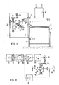
- FIG. 1 shows an X-ray device with a tilting table 2 which is rotatably attached to a device base 1 and to which a guide tower 3 for a target device carriage 4 is attached, which guides the target device 5 with an X-ray image intensifier television chain wearing.
- a patient support plate 6 is movably mounted on the tilting table 2.
- the guide tower 3 is shown pivoted through 90 ° for a better overview.
- the target device carriage 4 In the guide tower 3, the target device carriage 4, supported by rollers 7, runs along guide rails 8. On its inner part, the target device carriage 4 has a slot-shaped opening 9 into which a roller 11 attached to a one-armed load lever 10 slides.
- the load lever 10 is rotatably connected to the guide tower 3 at its other end. Between the two ends, the load lever 10 is pivotally connected to a sleeve 13 which is slidably mounted on a rod 12 and which is supported via a spring 14 on a fastening member 15 attached to the end of the rod 12.
- the other end of the rod 12 is connected in an articulated manner to a nut 17 which is adjustable by means of a threaded spindle 16.
- the threaded spindle 16 is driven by a motor 19 via a reduction gear 18.
- An angle sensor 21 is attached to the tilting table 2, which is coupled to the device base 1 and detects the inclined position of the tilting table 2.
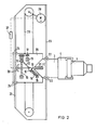
- FIG. 2 shows a further application of the spring weight compensation according to the invention, which compensates for the guide tower 3 running on rollers 22 along guide rails 23 with the target device 5.
- the spring weight compensation 10 to 20 is arranged on a longitudinal carriage 26 running on rollers 24 in guide rails 25. It engages with its load lever 10 in a slot-shaped opening 27 attached to the guide tower 3. Via a chain 29 operated by a motor 28, which is connected to the longitudinal carriage 26, the latter is adjusted such that the load lever 10 is in the desired position of the Guide tower 3 is always aligned in its central position, as shown.
- the position of the load lever 10 is determined by a transducer 30 coupled to it.
- the output signal of the functional memory 32 is fed to a first comparison stage 34, which is connected to an amplifier stage 35 for the motor 19.
- the motor 19 is mechanically connected via the reduction gear 18, the threaded spindle 16 and the nut 17 to the length sensor 20, the a signal proportional to the position of the nut 17 of a second comparison stage 36 are supplied with adjustable values A which correspond to the expansion stages and thus the weight of the Target device 5 correspond and thus represent the target value for the counterforce to be set.
- the second comparison stage 36 is connected to the second input of the first comparison stage 34 and supplies it with a control variable corresponding to the deviation from the target value of the force to be compensated. This is compared with the angular function and the nut 17 is adjusted accordingly by the motor 19, so that the counterforce acting at the end of the load lever 10 completely compensates for the weight of the car to be compensated.
- the movable longitudinal carriage 26 increases this in the exemplary embodiment according to FIG.
- the load lever 10 is moved out of its central position. This change in position is recognized by the transducer 30, which feeds a signal to a further control circuit 37, which then switches on the motor 28, so that the longitudinal carriage 26 is tracked until the load lever 10 is again in its central position shown. This means that there are sufficient reserves available for tracking, even if the examiner should make a quick movement.
- the spring weight compensation is set in the same way as was described with reference to FIG. 3.
Landscapes
- Health & Medical Sciences (AREA)
- Life Sciences & Earth Sciences (AREA)
- Medical Informatics (AREA)
- Engineering & Computer Science (AREA)
- Radiology & Medical Imaging (AREA)
- Biomedical Technology (AREA)
- Biophysics (AREA)
- Nuclear Medicine, Radiotherapy & Molecular Imaging (AREA)
- Optics & Photonics (AREA)
- Pathology (AREA)
- Physics & Mathematics (AREA)
- High Energy & Nuclear Physics (AREA)
- Heart & Thoracic Surgery (AREA)
- Molecular Biology (AREA)
- Surgery (AREA)
- Animal Behavior & Ethology (AREA)
- General Health & Medical Sciences (AREA)
- Public Health (AREA)
- Veterinary Medicine (AREA)
- Apparatus For Radiation Diagnosis (AREA)
Applications Claiming Priority (2)
| Application Number | Priority Date | Filing Date | Title |
|---|---|---|---|
| DE8513305U DE8513305U1 (de) | 1985-05-06 | 1985-05-06 | Röntgengerät mit Federgewichtsausgleich |
| DE8513305U | 1985-05-06 |
Publications (2)
| Publication Number | Publication Date |
|---|---|
| EP0200987A1 true EP0200987A1 (fr) | 1986-11-12 |
| EP0200987B1 EP0200987B1 (fr) | 1989-07-12 |
Family
ID=6780730
Family Applications (1)
| Application Number | Title | Priority Date | Filing Date |
|---|---|---|---|
| EP86105540A Expired EP0200987B1 (fr) | 1985-05-06 | 1986-04-22 | Appareil de radiologie comportant un système d'équilibrage à ressort |
Country Status (4)
| Country | Link |
|---|---|
| US (1) | US4715057A (fr) |
| EP (1) | EP0200987B1 (fr) |
| JP (1) | JPH0423530Y2 (fr) |
| DE (2) | DE8513305U1 (fr) |
Families Citing this family (18)
| Publication number | Priority date | Publication date | Assignee | Title |
|---|---|---|---|---|
| DE3635700A1 (de) * | 1986-10-21 | 1988-04-28 | Michael Schmeller | Hubeinrichtung |
| US4986273A (en) * | 1989-08-07 | 1991-01-22 | Medical & Scientific Enterprises, Inc. | Method of radiologically scanning the spine for measuring bone density |
| USRE34511E (en) * | 1987-05-15 | 1994-01-18 | Hologic, Inc. | Method of radiologically scanning the spine for measuring bone density |
| US5150394A (en) | 1989-12-05 | 1992-09-22 | University Of Massachusetts Medical School | Dual-energy system for quantitative radiographic imaging |
| US6031892A (en) * | 1989-12-05 | 2000-02-29 | University Of Massachusetts Medical Center | System for quantitative radiographic imaging |
| US5131105A (en) * | 1990-11-21 | 1992-07-21 | Diasonics, Inc. | Patient support table |
| US5230112A (en) * | 1990-11-21 | 1993-07-27 | Diasonics, Inc. | Patient support table |
| JP2558398Y2 (ja) * | 1993-03-31 | 1997-12-24 | 株式会社島津製作所 | 移動型x線診断装置 |
| US6217214B1 (en) | 1993-11-22 | 2001-04-17 | Hologic, Inc. | X-ray bone densitometry apparatus |
| US5838765A (en) * | 1993-11-22 | 1998-11-17 | Hologic, Inc. | Whole-body x-ray bone densitometry using a narrow-angle fan beam, including variable fan beam displacement between scan passes |
| US6059455A (en) * | 1993-11-22 | 2000-05-09 | Hologic, Inc. | Portable X-ray bone densitometry system |
| US5748705A (en) * | 1993-11-22 | 1998-05-05 | Hologic Inc. | X-ray bone densitometry |
| US5432834A (en) * | 1993-11-22 | 1995-07-11 | Hologic, Inc. | Whole-body dual-energy bone densitometry using a narrow angle fan beam to cover the entire body in successive scans |
| US5687211A (en) * | 1993-11-22 | 1997-11-11 | Hologic, Inc. | Bone densitometry scanning system and method for selecting scan parametric values using x-ray thickness measurement |
| DE4432448C2 (de) * | 1994-09-12 | 1998-08-27 | Siemens Ag | Gewichtsausgleichseinrichtung |
| US5715820A (en) * | 1995-06-06 | 1998-02-10 | Hologic, Inc. | X-ray bone densitometry using multiple pass scanning with image blending |
| CN108332014B (zh) * | 2018-01-19 | 2019-09-03 | 杭州左中右网络科技有限公司 | 基于蓝牙通讯解锁的微公交运行管理系统 |
| CN114798767B (zh) * | 2022-04-20 | 2023-06-20 | 山东鑫泰新材料科技有限公司 | 一种用于热轧卷镰刀弯检测的装置及其使用方法 |
Citations (3)
| Publication number | Priority date | Publication date | Assignee | Title |
|---|---|---|---|---|
| DE1728886U (de) * | 1955-04-18 | 1956-08-30 | Siemens Reiniger Werke Ag | Roentgengeraet. |
| DE968324C (de) * | 1954-05-20 | 1958-02-06 | Siemens Reiniger Werke Ag | Roentgengeraet mit an einer umlegbaren Patientenlagerstatt unter Gewichtsausgleich verstellbar angeordneten Geraeteteilen |
| DE1047988B (de) * | 1955-03-19 | 1958-12-31 | Mueller C H F Ag | Roentgengeraet mit Gewichtsausgleich |
Family Cites Families (3)
| Publication number | Priority date | Publication date | Assignee | Title |
|---|---|---|---|---|
| US2901202A (en) * | 1954-12-03 | 1959-08-25 | Picker X Ray Corp Waite Mfg | Counter balance |
| US4166602A (en) * | 1978-05-18 | 1979-09-04 | Pennwalt Corporation | Counterbalancing mechanism for X-ray tubeheads |
| US4590378A (en) * | 1984-06-04 | 1986-05-20 | Siemens Gammasonics, Inc. | Counterbalanced radiation detection device |
-
1985
- 1985-05-06 DE DE8513305U patent/DE8513305U1/de not_active Expired
-
1986
- 1986-04-22 EP EP86105540A patent/EP0200987B1/fr not_active Expired
- 1986-04-22 DE DE8686105540T patent/DE3664254D1/de not_active Expired
- 1986-05-01 JP JP1986066872U patent/JPH0423530Y2/ja not_active Expired
- 1986-05-01 US US06/857,967 patent/US4715057A/en not_active Expired - Fee Related
Patent Citations (3)
| Publication number | Priority date | Publication date | Assignee | Title |
|---|---|---|---|---|
| DE968324C (de) * | 1954-05-20 | 1958-02-06 | Siemens Reiniger Werke Ag | Roentgengeraet mit an einer umlegbaren Patientenlagerstatt unter Gewichtsausgleich verstellbar angeordneten Geraeteteilen |
| DE1047988B (de) * | 1955-03-19 | 1958-12-31 | Mueller C H F Ag | Roentgengeraet mit Gewichtsausgleich |
| DE1728886U (de) * | 1955-04-18 | 1956-08-30 | Siemens Reiniger Werke Ag | Roentgengeraet. |
Also Published As
| Publication number | Publication date |
|---|---|
| DE3664254D1 (en) | 1989-08-17 |
| JPH0423530Y2 (fr) | 1992-06-02 |
| EP0200987B1 (fr) | 1989-07-12 |
| US4715057A (en) | 1987-12-22 |
| JPS61182706U (fr) | 1986-11-14 |
| DE8513305U1 (de) | 1986-09-04 |
Similar Documents
| Publication | Publication Date | Title |
|---|---|---|
| EP0200987B1 (fr) | Appareil de radiologie comportant un système d'équilibrage à ressort | |
| DE102007056266B4 (de) | Presse | |
| WO2014111500A1 (fr) | Dispositif de guidage d'au moins une conduite d'un robot à bras articulé et robot à bras articulé | |
| DE4412698B4 (de) | Federbetätigte Vorschubvorrichtung mit Gelenkgetriebesteuerung | |
| EP0244011A2 (fr) | Appareil de radiologie pourvu d'une partie motorisée | |
| DE19624639C2 (de) | Vorrichtung zum Verschwenken einer Walze für eine laufende Bahn | |
| EP0351672A1 (fr) | Dispositif pour commander la force de pression d'une bobine sur un cylindre de friction | |
| CH679691A5 (fr) | ||
| EP1729037B1 (fr) | Transmission d'anneau de friction | |
| DE2342668A1 (de) | Mengenregler fuer fliessende produkte, insbesondere schuettgueter | |
| DE3215566A1 (de) | Antrieb zur scharfstellung eines mikroskopes | |
| DE1605363C3 (de) | Vorrichtung an einem zur Messung, Registrierung und/oder Korrektur der Lage von Gleisen dienenden Fahrzeug, insbesondere Gleisrichtmaschine | |
| DE102019124750A1 (de) | Bandsägemaschine und Verfahren zum Betrieb einer Bandsägemaschine | |
| EP2163503A2 (fr) | Appareil de manipulation pour déplacer des objets, notamment balancier | |
| DE3121373A1 (de) | Geraet zum insbesondere dreidimensionalen messen und/oder anreissen und/oder antasten von werkstuecken | |
| EP4225569A1 (fr) | Système de réglage pour régler le jeu de guidage d'un guide coulissant pour des parties mobiles d'une presse et procédé pour régler la position d'au moins un coulisseau d'un guide coulissant sur une presse | |
| EP0429815B1 (fr) | Dispositif pour formage d'une bride ou similaire, en particulier à la fin d'un tube métallique à paroi mince | |
| DE2544783C3 (de) | Positionsregelung für eine sich bewegende Bahn | |
| DE19832214C1 (de) | Kalander | |
| DE2806056A1 (de) | Geraet zur regelung und korrektur der axialverschiebungen grosser sich drehender zylinder | |
| DE3712877C1 (en) | Device for adjusting the longitudinal register of a printing carrier web | |
| DE1402654A1 (de) | Vorrichtung und Verfahren zur Regelung der Zugspannung in bahnfoermigem Material,insbesondere Bandstahl | |
| EP0058827A2 (fr) | Outil à levier | |
| DD257969A1 (de) | Roentgengeraet mit einem motorisch verstellbaren geraeteteil | |
| DE4238487A1 (de) | Federgewichtsausgleich für Röntgengerät |
Legal Events
| Date | Code | Title | Description |
|---|---|---|---|
| PUAI | Public reference made under article 153(3) epc to a published international application that has entered the european phase |
Free format text: ORIGINAL CODE: 0009012 |
|
| AK | Designated contracting states |
Kind code of ref document: A1 Designated state(s): DE FR GB |
|
| PUAB | Information related to the publication of an a document modified or deleted |
Free format text: ORIGINAL CODE: 0009199EPPU |
|
| PUAF | Information related to the publication of a search report (a3 document) modified or deleted |
Free format text: ORIGINAL CODE: 0009199SEPU |
|
| 17P | Request for examination filed |
Effective date: 19861203 |
|
| R17D | Deferred search report published (corrected) |
Effective date: 19861217 |
|
| RA1 | Application published (corrected) |
Date of ref document: 19861217 Kind code of ref document: A1 |
|
| 17Q | First examination report despatched |
Effective date: 19880316 |
|
| GRAA | (expected) grant |
Free format text: ORIGINAL CODE: 0009210 |
|
| AK | Designated contracting states |
Kind code of ref document: B1 Designated state(s): DE FR GB |
|
| REF | Corresponds to: |
Ref document number: 3664254 Country of ref document: DE Date of ref document: 19890817 |
|
| ET | Fr: translation filed | ||
| GBT | Gb: translation of ep patent filed (gb section 77(6)(a)/1977) | ||
| PLBE | No opposition filed within time limit |
Free format text: ORIGINAL CODE: 0009261 |
|
| STAA | Information on the status of an ep patent application or granted ep patent |
Free format text: STATUS: NO OPPOSITION FILED WITHIN TIME LIMIT |
|
| 26N | No opposition filed | ||
| PGFP | Annual fee paid to national office [announced via postgrant information from national office to epo] |
Ref country code: GB Payment date: 19920326 Year of fee payment: 7 |
|
| PGFP | Annual fee paid to national office [announced via postgrant information from national office to epo] |
Ref country code: FR Payment date: 19920428 Year of fee payment: 7 |
|
| PGFP | Annual fee paid to national office [announced via postgrant information from national office to epo] |
Ref country code: DE Payment date: 19920625 Year of fee payment: 7 |
|
| PG25 | Lapsed in a contracting state [announced via postgrant information from national office to epo] |
Ref country code: GB Effective date: 19930422 |
|
| GBPC | Gb: european patent ceased through non-payment of renewal fee |
Effective date: 19930422 |
|
| PG25 | Lapsed in a contracting state [announced via postgrant information from national office to epo] |
Ref country code: FR Effective date: 19931229 |
|
| PG25 | Lapsed in a contracting state [announced via postgrant information from national office to epo] |
Ref country code: DE Effective date: 19940101 |
|
| REG | Reference to a national code |
Ref country code: FR Ref legal event code: ST |