EP0201021A2 - Electric synchronous motor with a disc-shaped rotor - Google Patents
Electric synchronous motor with a disc-shaped rotor Download PDFInfo
- Publication number
- EP0201021A2 EP0201021A2 EP86105846A EP86105846A EP0201021A2 EP 0201021 A2 EP0201021 A2 EP 0201021A2 EP 86105846 A EP86105846 A EP 86105846A EP 86105846 A EP86105846 A EP 86105846A EP 0201021 A2 EP0201021 A2 EP 0201021A2
- Authority
- EP
- European Patent Office
- Prior art keywords
- magnetic
- disc
- parts
- annular
- magnetic disc
- Prior art date
- Legal status (The legal status is an assumption and is not a legal conclusion. Google has not performed a legal analysis and makes no representation as to the accuracy of the status listed.)
- Granted
Links
Images


Classifications
-
- H—ELECTRICITY
- H02—GENERATION; CONVERSION OR DISTRIBUTION OF ELECTRIC POWER
- H02K—DYNAMO-ELECTRIC MACHINES
- H02K21/00—Synchronous motors having permanent magnets; Synchronous generators having permanent magnets
- H02K21/12—Synchronous motors having permanent magnets; Synchronous generators having permanent magnets with stationary armatures and rotating magnets
- H02K21/24—Synchronous motors having permanent magnets; Synchronous generators having permanent magnets with stationary armatures and rotating magnets with magnets axially facing the armatures, e.g. hub-type cycle dynamos
-
- H—ELECTRICITY
- H02—GENERATION; CONVERSION OR DISTRIBUTION OF ELECTRIC POWER
- H02K—DYNAMO-ELECTRIC MACHINES
- H02K19/00—Synchronous motors or generators
- H02K19/02—Synchronous motors
Definitions
- the present invention relates to a synchronous electric motor according to the preamble of claim 1.
- the object of the present invention is to provide a motor making it possible to obtain a high torque and a large number of steps per revolution for a minimum radial dimension of the motor.
- the engine according to the invention includes the arrangement described in the characteristic part of claim 1.
- the engine shown in Figures 1 and 2 comprises a shaft 1, in this case a hollow shaft of a relatively large diameter compared to the radial dimensions of the engine.
- the shaft 1 is rotatably mounted, by means of ball bearings 2, 3, in a stator assembly 4 formed of two sub-assemblies respectively comprising parts 41, 42 and 43, 44 made for example of aluminum or a plastic material.
- the outer ring 8 of the bearing 2 is mounted on the part 41 of the stator.
- This piece 41 has notches in the radial direction of the motor, in which are arranged pieces 9, flat, in the shape of a "U”, made of a material of very good magnetic permeability.
- a second series of such "U” shaped parts, designated by 10, is placed in corresponding notches of the part 42 of the same stator sub-assembly.
- each "U" constitute polar parts, the free ends of which have polar surfaces, the polar surfaces of a pair of parts 9, 10 being arranged facing each other, so as to form air gaps 11, 12.
- Coils electrical annular, coaxial 13, 14 are arranged so as to fit into the space formed between the branches of the "U", 9 and 10, respectively.
- Each pair of parts 9, 10 constitutes an elementary magnetic circuit comprising two air gaps and being coupled with the two coils 13 and 14.
- the annular disc 5 is magnetized in the axial direction, so as to reveal on each of its surfaces magnetic poles of alternating polarities, ie N and S, these poles being distributed substantially regularly along two concentric annular zones 51, 52, indicated in Figure 2.
- the N and S poles have been shown by dashed lines. The dimensions of these poles are substantially equal to those of the polar surfaces formed by the ends of the branches of "U" of the parts 9 and 10, the radial distances of the two zones 51 and 52 corresponding to the radial distances of the air gaps 11 and 12 formed by the parts 9 and 10.
- the poles of the magnetic annular disc being distributed substantially regularly along each zone, the angular spacing of the center lines of the poles is substantially ⁇ / N for a number of poles de2N appearing in each of the zones 51 and 52 on the same face of the disc.
- the average angular spacing of the axial median planes of the elementary magnetic circuits 10 is 2x / N.
- the effective spacing between two neighboring circuits may be slightly different from this average value, in order to compensate for the influence of certain harmonics of the motor torque.
- the poles of the same name located in both of the two concentric zones 51 and 52, on the same face of the disc are offset by 1C / N with respect to each other, as shown in the figure 2.
- the motor of FIG. 1 is a two-stage motor, the first comprising the magnetic disc 5, and the second, quite similar, a magnetic disc 15, the latter cooperating with the subset of stators comprising the parts 43 and 44 mentioned above.
- the structure of the second stage is similar to that which has just been described in relation to the first.
- Each stage constitutes, for example, a phase of a two-phase motor.
- Figures 3 and 4 on the one hand, and 5 and 6 on the other hand, illustrate the alternative embodiments of the motor of Figure 1, in which the poles appearing on each side of the magnetic disc 35 are of the same name in the same angular sector of the disc. It is therefore necessary to provide an angular offset between the pole portions of each "U" shaped piece, such as 49 according to FIG. 4, or 69 according to FIG. 6.
- the two pole parts are folded from a straight base portion, so as to form an angle with respect to it and between them, in the radial direction.
- the two pole parts are parallel to each other, and it is the base portion of the part 69 which is folded, so as to offset the two pole parts.
- the magnetization of the disc 35 is simplified due to the alignment and the continuity of the poles between the two annular zones cooperating with the pole surfaces of the "U" shaped parts.
- FIG. 7 shows another embodiment of an elementary magnetic circuit, according to which three pole parts, such as 77, 78, 79, are arranged on each side of a magnetic disc 75, these three pole parts being connected between them by a common cylinder head portion 76.
- Two coaxial annular coils 73, 74 are coupled with the "W" shaped parts thus formed on each side of the disc 75.
- the latter has three concentric annular magnetic zones on each of its faces , the poles formed in each angular sector being of the same polarity in the external and internal zones, and being of opposite polarities in the zone of the medium, in accordance with the succession of the poles appearing on the polar surfaces of the parts 77, 78 and 79.
- the coils 73 and 74 are, of course, supplied so that the same polarity appears on the common pole piece 78.
- the advantage of the embodiment of FIG. 7 is an increase in the torque of the motor by a relatively small increase in the radial dimension of the latter.
- FIG. 8 illustrates an embodiment aimed at providing a particularly flat motor.
- the elementary magnetic circuits are formed by a single piece in the shape of a "U", 89, arranged in a similar manner to that shown in FIG. 1 and coupled with a similar annular coil 83, the circuit being closed by a yoke part arranged on the opposite side of the magnetic disc 85.
- this yoke part 86 is integral with the magnetic disc, but it could also be fixed, and spaced from the disc 85 like the part 10 of figure 1.
- FIG. 9 An embodiment similar to that of FIG. 1 is represented in FIG. 9, in which the same elements have been designated by the same reference numbers as in FIG. 1.
- the polar parts of the elementary magnetic circuits such as 95, 96, are interconnected by a common annular yoke part, produced for example by a laminated assembly, such as 97 in FIG. 9.
- Such an embodiment is particularly advantageous from the point of view of view of the manufacture of parts and assembly of the engine.
Landscapes
- Engineering & Computer Science (AREA)
- Power Engineering (AREA)
- Permanent Magnet Type Synchronous Machine (AREA)
- Brushless Motors (AREA)
- Iron Core Of Rotating Electric Machines (AREA)
Abstract
Le moteur comporte une partie de rotor en forme de disque annulaire aimanté (5) et un ensemble de circuits magnétiques élémentaires (9, 10), chaque circuit comportant au moins deux parties polaires plates, rectangulaires, disposées essentiellement radialement et formant des entrefers respectifs (11, 12) dans lesquels est placé le disque (5). Ces entrefers sont espacés radialement et coopèrent avec deux zones annulaires concentriques du disque.The motor comprises a rotor part in the form of a magnetic annular disc (5) and a set of elementary magnetic circuits (9, 10), each circuit comprising at least two flat, rectangular polar parts, arranged essentially radially and forming respective air gaps ( 11, 12) in which the disc (5) is placed. These air gaps are spaced radially and cooperate with two concentric annular zones of the disc.
Une bobine de commande (13) est disposée dans l'espace formé entre lesdites parties polaires.A control coil (13) is arranged in the space formed between said pole parts.
Cette disposition permet de réaliser un moteur présentant un couple élevé et un grand nombre de pas par tour pour une dimension radiale minimale.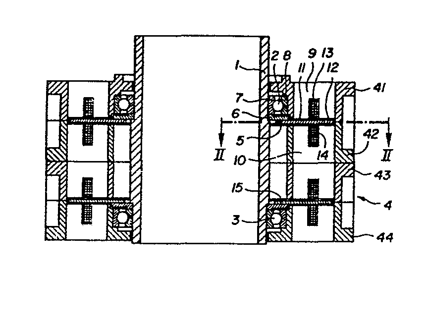
Description
La présente invention concerne un moteur électrique synchrone selon le préambule de la revendication 1.The present invention relates to a synchronous electric motor according to the preamble of claim 1.
Un tel moteur est décrit, par exemple, dans le brevet suisse No. 637 508. La conception originale de ce moteur est adaptée à des moteurs de relativement petite taille et d'une puissance nettement inférieure à 1 kilowatt. Pour des moteurs de taille plus grande, il s'est avéré que la structure prévue à l'origine n'offre pas la relation optimale entre le couple produit et l'encombrement du moteur, notamment en ce qui concerne sa dimension radiale.Such an engine is described, for example, in Swiss Patent No. 637 508. The original design of this engine is suitable for engines of relatively small size and with a power significantly less than 1 kilowatt. For larger motors, it has been found that the structure originally provided does not offer the optimal relationship between the torque produced and the size of the motor, in particular as regards its radial dimension.
La présente invention a pour but de fournir un moteur permettant d'obtenir un couple élevé et un grand nombre de pas par tour pour une dimension radiale minimale du moteur.The object of the present invention is to provide a motor making it possible to obtain a high torque and a large number of steps per revolution for a minimum radial dimension of the motor.
A cet effet, le moteur selon l'invention comporte la disposition décrite dans la partie caractéristique de la revendication 1.To this end, the engine according to the invention includes the arrangement described in the characteristic part of claim 1.
Des formes d'exécution particulières du moteur selon l'invention sont décrites dans les revendications 2 à 11.Particular embodiments of the engine according to the invention are described in
D'autres caractéristiques et avantages de l'invention ressortiront de la description donnée ci-après de différentes formes d'exécution, avec référence au dessin annexé, dans lequel :
- La figure 1 est une vue en coupe axiale d'une première forme d'exécution du moteur selon l'invention,
- la figure 2 est une vue en coupe selon la ligne II-II de la figure 1, à une échelle plus grande,
- la figure 3 est une vue en coupe partielle, similaire à une partie de la figure 2, d'une première variante d'exécution du moteur de la figure 1,
- la figure 4 est une vue en perspective d'une pièce en forme de "U" d'un circuit magnétique élémentaire utilisé dans le moteur de la figure 3,
- la figure 5 est une vue en coupe partielle, similaire à celle de la figure 3, d'une deuxième variante d'exécution du moteur de la figure 1,
- la figure 6 est une vue en perspective, similaire à celle de la figure 4, d'une pièce en forme de "U" utilisée dans la variante d'exécution du moteur selon la figure 5,
- la figure 7 est une vue en coupe partielle, similaire à une partie de la figure 1, montrant une autre forme d'exécution d'un circuit magnétique élémentaire,
- la figure 8 est une vue en coupe partielle, similaire à celle de la figure 1, correspondant à une autre forme de réalisation du moteur, et
- la figure 9 est une vue en coupe similaire à celle de la figure 1, montrant une forme d'exécution alternative du moteur de la figure 1.
- FIG. 1 is a view in axial section of a first embodiment of the engine according to the invention,
- FIG. 2 is a sectional view along the line II-II of FIG. 1, on a larger scale,
- FIG. 3 is a partial sectional view, similar to a part of FIG. 2, of a first alternative embodiment of the engine of FIG. 1,
- FIG. 4 is a perspective view of a U-shaped part of an elementary magnetic circuit used in the motor of FIG. 3,
- FIG. 5 is a partial sectional view, similar to that of FIG. 3, of a second alternative embodiment of the engine of FIG. 1,
- FIG. 6 is a perspective view, similar to that of FIG. 4, of a part in the shape of a "U" used in the alternative embodiment of the engine according to FIG. 5,
- FIG. 7 is a partial sectional view, similar to a part of FIG. 1, showing another embodiment of an elementary magnetic circuit,
- FIG. 8 is a partial sectional view, similar to that of FIG. 1, corresponding to another embodiment of the engine, and
- FIG. 9 is a sectional view similar to that of FIG. 1, showing an alternative embodiment of the motor of FIG. 1.
Le moteur représenté aux figures 1 et 2 comporte un arbre 1, en l'occurrence un arbre creux d'un diamètre relativement important par rapport aux dimensions radiales du moteur. L'arbre 1 est monté de façon rotative, au moyen de roulements à billes 2, 3, dans un ensemble de stator 4 formé de deux sous-ensembles comportant respectivement des pièces 41, 42 et 43, 44 réalisées par exemple en aluminium ou en une matière plastique.The engine shown in Figures 1 and 2 comprises a shaft 1, in this case a hollow shaft of a relatively large diameter compared to the radial dimensions of the engine. The shaft 1 is rotatably mounted, by means of
Un premier disque annulaire 5, en un matériau aimantable tel que le samarium-cobalt, est monté par l'intermédiaire d'une pièce de support annulaire 6 sur la bague intérieure 7 du roulement à billes 2, cette bague étant solidaire de l'arbre 1. La bague extérieure 8 du roulement 2 est montée sur la pièce 41 du stator. Cette pièce 41 comporte des encoches dans le sens radial du moteur, dans lesquelles sont disposées des pièces 9, plates, en forme de "U", réalisées en un matériau de très bonne perméabilité magnétique. Une deuxième série de telles pièces en forme de "U", désignées par 10, est placée dans des encoches correspondantes de la pièce 42 du même sous-ensemble de stator. Les deux branches de chaque "U" constituent des parties polaires dont les extrémités libres présentent des surfaces polaires, les surfaces polaires d'une paire de pièces 9, 10 étant disposées en regard, de façon à former des entrefers 11, 12. Des bobines électriques annulaires, coaxiales 13, 14 sont disposées de façon à s'insérer dans l'espace formé entre les branches des "U", 9 et 10, respectivement. Chaque paire de pièces 9, 10 constitue un circuit magnétique élémentaire comportant deux entrefers et étant couplé avec les deux bobines 13 et 14.A first
Le disque annulaire 5 est aimanté en direction axiale, de façon à faire apparaître sur chacune de ses surfaces des pôles magnétiques de polarités alternantes, soit N et S, ces pôles étant répartis sensiblement régulièrement le long de deux zones annulaires concentriques 51, 52, indiqués sur la figure 2. Sur cette figure, les pôles N et S ont été montrés par des traits mixtes. Les dimensions de ces pôles sont sensiblement égales à celles des surfaces polaires formées par les extrémités des branches de "U" des pièces 9 et 10, les distances radiales des deux zones 51 et 52 correspondant aux distances radiales des entrefers 11 et 12 formés par les pièces 9 et 10.The
Les pôles du disque annulaire aimanté étant répartis sensiblement régulièrement le long de chaque zone, l'espacement angulaire des lignes médianes des pôles est sensiblement de π/N pour un nombre de pôles de2N apparaissant dans chacune des zones 51 et 52 sur une même face du disque. L'espacement angulaire moyen des plans médians axiaux des circuits magnétiques élémentaires 10 est de 2x/N. L'espacement effectif entre deux circuits voisins peut être légèrement différent de cette valeur moyenne, afin de compenser l'influence de certaines harmoniques du couple du moteur.The poles of the magnetic annular disc being distributed substantially regularly along each zone, the angular spacing of the center lines of the poles is substantially π / N for a number of poles de2N appearing in each of the
Les pôles magnétiques apparaissant aux surfaces polaires d'une pièce 9 ou 10 sous l'effet du courant dans les bobines 13 et 14, étant de noms différents d'un même côté du disque aimanté, les pôles magnétiques du disque aimanté situés sur une même face de ce disque et ayant la même ligne médiane sont également de noms différents. Autrement dit, les pôles de même nom se trouvant dans l'une et l'autre des deux zones concentriques 51 et 52, sur une même face du disque, sont décalés de1C/N les uns par rapport aux autres, comme le montre la figure 2.The magnetic poles appearing on the polar surfaces of a
Le moteur de la figure 1 est un moteur à deux étages, le premier comportant le disque aimanté 5, et le deuxième, tout à fait similaire, un disque aimanté 15, ce dernier coopérant avec le sous-ensemble de stators comportant les pièces 43 et 44 mentionnées plus haut. La structure du deuxième étage est analogue à celle qui vient d'être décrite en rapport avec le premier. Chaque étage constitue, par exemple, une phase d'un moteur diphasé.The motor of FIG. 1 is a two-stage motor, the first comprising the
Il est à noter que la forme des circuits magnétiques élémentaires, telle que décrite ci-dessus, permet d'utiliser, pour un diamètre extérieur donné du moteur , un disque aimanté d'un diamètre maximal, et d'utiliser de larges zones aimantées sur ce disque. L'efficacité et le rendement atteignent, par conséquent, des valeurs très importantes pour un encombrement donné.It should be noted that the shape of the elementary magnetic circuits, as described above, makes it possible to use, for a given external diameter of the motor, a magnetic disc of maximum diameter, and to use large magnetic zones on this disc. Efficiency and yield therefore reach very important values for a given space requirement.
Les figures 3 et 4 d'une part, et 5 et 6 d'autre part, illustrent les variantes d'exécution du moteur de la figure 1, dans lesquelles les pôles apparaissant sur chaque face du disque aimanté 35 sont de même nom dans le même secteur angulaire du disque. Il est donc nécessaire de prévoir un décalage angulaire entre les parties polaires de chaque pièce en forme de "U", telle que 49 selon la figure 4, ou 69 selon la figure 6. Dans la forme d'exécution selon la figure 4, les deux parties polaires sont pliées à partir d'une portion de base droite, de façon à former un angle par rapport à celle-ci et entre elles, dans le sens radial. Selon la figure 6, les deux parties polaires sont parallèles entre elles, et c'est la portion de base de la pièce 69 qui est pliée, de façon à réaliser le décalage des deux parties polaires. Dans les deux cas, l'aimantation du disque 35 se trouve simplifiée du fait de l'alignement et de la continuité des pôles entre les deux zones annulaires coopérant avec les surfaces polaires des pièces en forme de "U".Figures 3 and 4 on the one hand, and 5 and 6 on the other hand, illustrate the alternative embodiments of the motor of Figure 1, in which the poles appearing on each side of the
La figure 7 représente une autre forme d'exécution d'un circuit magnétique élémentaire, selon laquelle trois parties polaires, telles que 77, 78, 79, sont disposées de chaque côté d'un disque aimanté 75, ces trois parties polaires étant reliées entre elles par une portion de culasse commune 76. Deux bobines annulaires coaxiales 73, 74 sont couplées avec les pièces en forme de "W" ainsi formées de chaque côté du disque 75. Celui-ci présente trois zones aimantées annulaires concentriques sur chacune de ses faces, les pôles formés dans chaque secteur angulaire étant de même polarité dans les zones extérieure et intérieure, et étant de polarités opposées dans la zone du milieu, conformément à la succession des pôles apparaissant sur les surfaces polaires des parties 77, 78 et 79. Les bobines 73 et 74 sont, bien entendu, alimentées de façon que la même polarité apparaisse sur la pièce polaire commune 78.FIG. 7 shows another embodiment of an elementary magnetic circuit, according to which three pole parts, such as 77, 78, 79, are arranged on each side of a
L'avantage de la forme d'exécution de la figure 7 est une augmentation du couple du moteur par une augmentation relativement faible de la dimension radiale de celui-ci.The advantage of the embodiment of FIG. 7 is an increase in the torque of the motor by a relatively small increase in the radial dimension of the latter.
La figure 8 illustre une forme d'exécution visant à fournir un moteur particulièrement plat. Dans ce cas, les circuits magnétiques élémentaires sont formés par une seule pièce en forme de "U", 89, disposée de façon similaire à celle montrée à la figure 1 et couplée avec une bobine annulaire similaire 83, la fermeture du circuit étant réalisée par une partie de culasse disposée sur le côté opposé du disque aimanté 85. Dans l'exemple de la figure 8, cette partie de culasse 86 est solidaire du disque aimanté, mais elle pourrait également être fixe, et espacée du disque 85 comme la partie 10 de la figure 1.FIG. 8 illustrates an embodiment aimed at providing a particularly flat motor. In this case, the elementary magnetic circuits are formed by a single piece in the shape of a "U", 89, arranged in a similar manner to that shown in FIG. 1 and coupled with a similar
Une forme d'exécution similaire à celle de la figure 1 est représentée à la figure 9, dans laquelle les mêmes éléments ont été désignés par les mêmes chiffres de référence que dans la figure 1. Dans cette forme d'exécution, les parties polaires des circuits magnétiques élémentaires, telles que 95, 96, sont reliées entre elles par une partie de culasse commune annulaire, réalisée par exemple par un ensemble feuilleté, tel que 97 dans la figure 9. Une telle forme d'exécution est particulièrement intéressante du point de vue de la fabrication des pièces et du montage du moteur.An embodiment similar to that of FIG. 1 is represented in FIG. 9, in which the same elements have been designated by the same reference numbers as in FIG. 1. In this embodiment, the polar parts of the elementary magnetic circuits, such as 95, 96, are interconnected by a common annular yoke part, produced for example by a laminated assembly, such as 97 in FIG. 9. Such an embodiment is particularly advantageous from the point of view of view of the manufacture of parts and assembly of the engine.
Claims (11)
Applications Claiming Priority (2)
| Application Number | Priority Date | Filing Date | Title |
|---|---|---|---|
| CH1999/85A CH665922A5 (en) | 1985-05-10 | 1985-05-10 | SYNCHRONOUS ELECTRIC MOTOR WITH DISC SHAPE ROTOR. |
| CH1999/85 | 1985-05-10 |
Publications (3)
| Publication Number | Publication Date |
|---|---|
| EP0201021A2 true EP0201021A2 (en) | 1986-11-12 |
| EP0201021A3 EP0201021A3 (en) | 1987-07-22 |
| EP0201021B1 EP0201021B1 (en) | 1990-03-28 |
Family
ID=4223525
Family Applications (1)
| Application Number | Title | Priority Date | Filing Date |
|---|---|---|---|
| EP86105846A Expired - Lifetime EP0201021B1 (en) | 1985-05-10 | 1986-04-28 | Electric synchronous motor with a disc-shaped rotor |
Country Status (6)
| Country | Link |
|---|---|
| US (1) | US4658166A (en) |
| EP (1) | EP0201021B1 (en) |
| JP (1) | JPS6223351A (en) |
| KR (1) | KR860009521A (en) |
| CH (1) | CH665922A5 (en) |
| DE (1) | DE3669965D1 (en) |
Cited By (4)
| Publication number | Priority date | Publication date | Assignee | Title |
|---|---|---|---|---|
| DE3705089A1 (en) * | 1987-02-13 | 1988-08-25 | Weh Herbert | TRANSVERSAL FLOWING MACHINE IN COLLECTOR ARRANGEMENT |
| EP0357317A1 (en) * | 1988-08-30 | 1990-03-07 | Framo Developments (U.K.) Limited | Electric motor |
| WO1994002986A1 (en) * | 1992-07-20 | 1994-02-03 | Piller Gmbh | Electric machine |
| DE4314513A1 (en) * | 1993-05-03 | 1994-11-17 | Weh Herbert | Transverse-flux (transverse-flow) machines having combined PM excitation |
Families Citing this family (41)
| Publication number | Priority date | Publication date | Assignee | Title |
|---|---|---|---|---|
| CH665070A5 (en) * | 1985-12-06 | 1988-04-15 | Portescap | SYNCHRONOUS ELECTRIC MOTOR WITH MAGNET ROTOR AND MANUFACTURING METHOD THEREOF. |
| US4714854A (en) * | 1986-06-30 | 1987-12-22 | Portescap | Electric motor with a multipolar permanent magnet rotor |
| CH672566A5 (en) * | 1987-06-26 | 1989-11-30 | Portescap | |
| NL8801629A (en) * | 1988-06-27 | 1990-01-16 | Philips Nv | ELECTRIC MULTI-POLE MACHINE. |
| US5168187A (en) * | 1991-02-20 | 1992-12-01 | Dana Corporation, Warner Electric Brake & Clutch Division | Axial pole stepping motor |
| US5396140A (en) * | 1993-05-28 | 1995-03-07 | Satcon Technology, Corp. | Parallel air gap serial flux A.C. electrical machine |
| US5734217A (en) * | 1995-05-18 | 1998-03-31 | Aura Systems, Inc. | Induction machine using ferromagnetic conducting material in rotor |
| GB9516475D0 (en) * | 1995-08-11 | 1995-10-11 | Rolls Royce Power Eng | Electrical machine |
| US6043579A (en) * | 1996-07-03 | 2000-03-28 | Hill; Wolfgang | Permanently excited transverse flux machine |
| US5982074A (en) | 1996-12-11 | 1999-11-09 | Advanced Technologies Int., Ltd. | Axial field motor/generator |
| EP0924843A1 (en) * | 1997-12-17 | 1999-06-23 | Ssm Schärer Schweiter Mettler Ag | Apparatus for winding a thread on a bobbin |
| US6664704B2 (en) * | 2001-11-23 | 2003-12-16 | David Gregory Calley | Electrical machine |
| US6713925B2 (en) * | 2002-05-20 | 2004-03-30 | Karsten A. Laing | Electric motor with reduced axial length |
| US6986640B2 (en) * | 2002-05-20 | 2006-01-17 | Oliver Laing | Motor pump with expansion tank |
| US20040000824A1 (en) * | 2002-05-20 | 2004-01-01 | Laing Karsten A. | Electrical motor with spherically supported rotor |
| US6736616B2 (en) * | 2002-05-20 | 2004-05-18 | Oliver Laing | Centrifugal pump with integrated motor |
| US6713918B2 (en) | 2002-05-20 | 2004-03-30 | Oliver Laing | Spherical bearing for electrical machines with permanent magnetic rotors |
| US7484941B2 (en) * | 2002-05-20 | 2009-02-03 | Oliver Laing | Electric motor with circulator pump |
| DE10242833B4 (en) * | 2002-09-14 | 2011-06-01 | Mtu Aero Engines Gmbh | Electric drive device |
| US7081696B2 (en) * | 2004-08-12 | 2006-07-25 | Exro Technologies Inc. | Polyphasic multi-coil generator |
| BRPI0713121A2 (en) * | 2006-06-08 | 2012-04-17 | Exro Technologies Inc | polyphase multi-coil generator apparatus |
| DE102006050201A1 (en) * | 2006-10-25 | 2008-04-30 | Robert Bosch Gmbh | Transverse flux machine and method for producing a transverse flux machine |
| US7973446B2 (en) * | 2007-05-09 | 2011-07-05 | Motor Excellence, Llc | Electrical devices having tape wound core laminate rotor or stator elements |
| WO2008141214A1 (en) * | 2007-05-09 | 2008-11-20 | Motor Excellence, Llc. | Electrical output generating devices and driven electrical devices with reduced flux leakage using permanent magnet components, and methods of making and using the same |
| US20090026869A1 (en) * | 2007-07-24 | 2009-01-29 | Christian Kaehler | Transverse flux reluctance machine and method for manufacturing same |
| EP2342803A2 (en) * | 2008-11-03 | 2011-07-13 | Motor Excellence, LLC | Transverse and/or commutated flux system rotor concepts |
| DE102009004474B4 (en) * | 2009-01-13 | 2014-09-25 | Tirron-Elektronik Gmbh | Transverse flux machine with disc-shaped rotors |
| US8872395B2 (en) * | 2009-11-04 | 2014-10-28 | Fraen Mechatronics, Llc | Rotary single-phase electromagnetic actuator |
| WO2011115632A1 (en) | 2010-03-15 | 2011-09-22 | Motor Excellence Llc | Transverse and/or commutated flux systems configured to provide reduced flux leakage, hysteresis loss reduction, and phase matching |
| WO2011115633A1 (en) * | 2010-03-15 | 2011-09-22 | Motor Excellence Llc | Transverse and/or commutated flux system for electric bicycles |
| WO2011115634A1 (en) * | 2010-03-15 | 2011-09-22 | Motor Excellence Llc | Transverse and/or commutated flux systems having phase offset |
| US8952590B2 (en) | 2010-11-17 | 2015-02-10 | Electric Torque Machines Inc | Transverse and/or commutated flux systems having laminated and powdered metal portions |
| US8854171B2 (en) | 2010-11-17 | 2014-10-07 | Electric Torque Machines Inc. | Transverse and/or commutated flux system coil concepts |
| CN103477538A (en) | 2010-11-17 | 2013-12-25 | 电动转矩机器公司 | Transverse and/or commutated flux systems having segmented stator laminations |
| JP6324384B2 (en) * | 2012-08-31 | 2018-05-16 | リーンテック モーター ゲゼルシャフト ミット ベシュレンクテル ハフツング ウント コンパニー コマンディートゲゼルシャフトLEANTEC Motor GmbH & Co. KG | Electromechanical transducer |
| DE102015105991B4 (en) * | 2015-04-20 | 2018-10-04 | BITS Zwickau Büromat IT-Systeme GmbH | High power density electrical work machine |
| EP3586431A4 (en) | 2017-05-23 | 2020-11-11 | DPM Technologies Inc. | Variable coil configuration system control, apparatus and method |
| CA3111823A1 (en) | 2018-09-05 | 2020-03-12 | Dpm Technologies Inc. | Systems and methods for intelligent energy storage and provisioning using an energy storage control system |
| WO2020215154A1 (en) | 2019-04-23 | 2020-10-29 | Dpm Technologies Inc. | Fault tolerant rotating electric machine |
| US11897362B2 (en) | 2021-05-04 | 2024-02-13 | Exro Technologies Inc. | Systems and methods for individual control of a plurality of controllable units of battery cells |
| EP4324089A4 (en) | 2021-05-13 | 2024-10-23 | Exro Technologies Inc. | METHOD AND DEVICE FOR DRIVING COILS OF A MULTI-PHASE ELECTRICAL MACHINE |
Family Cites Families (10)
| Publication number | Priority date | Publication date | Assignee | Title |
|---|---|---|---|---|
| FR1271765A (en) * | 1960-09-05 | 1961-09-15 | Elektro Motoren A G | AC Rotary Electric Machine |
| US3396296A (en) * | 1967-06-05 | 1968-08-06 | Ernie B. Esters | Electric motors and generators |
| US3603823A (en) * | 1969-12-09 | 1971-09-07 | Elmer B Mason | Magnetic motor with plurality of stators |
| US3700944A (en) * | 1971-11-08 | 1972-10-24 | Ford Motor Co | Disc-type variable reluctance rotating machine |
| US3700943A (en) * | 1971-11-08 | 1972-10-24 | Ford Motor Co | Disc-type variable reluctance rotating machine |
| US4334166A (en) * | 1977-01-19 | 1982-06-08 | Kanto Kasei Kogyo Kabushiki Kaisha | Rotary magnetic sensor |
| US4330727A (en) * | 1979-12-27 | 1982-05-18 | Claude Oudet | Electric step motor |
| WO1983002042A1 (en) * | 1981-12-04 | 1983-06-09 | Oudet, Claude | Electric stepping motor |
| CH653189A5 (en) * | 1983-04-08 | 1985-12-13 | Portescap | ELECTRIC STEPPER MOTOR. |
| US4477745A (en) * | 1983-12-15 | 1984-10-16 | Lux Gregory F | Disc rotor permanent magnet generator |
-
1985
- 1985-05-10 CH CH1999/85A patent/CH665922A5/en not_active IP Right Cessation
-
1986
- 1986-04-17 KR KR1019860002966A patent/KR860009521A/en not_active Ceased
- 1986-04-28 DE DE8686105846T patent/DE3669965D1/en not_active Expired - Lifetime
- 1986-04-28 EP EP86105846A patent/EP0201021B1/en not_active Expired - Lifetime
- 1986-05-02 JP JP61102972A patent/JPS6223351A/en active Pending
- 1986-05-08 US US06/860,813 patent/US4658166A/en not_active Expired - Fee Related
Cited By (8)
| Publication number | Priority date | Publication date | Assignee | Title |
|---|---|---|---|---|
| DE3705089A1 (en) * | 1987-02-13 | 1988-08-25 | Weh Herbert | TRANSVERSAL FLOWING MACHINE IN COLLECTOR ARRANGEMENT |
| US5051641A (en) * | 1987-02-13 | 1991-09-24 | J. M. Voith Gmbh | Transversal flow machine in accumulator arrangement |
| EP0357317A1 (en) * | 1988-08-30 | 1990-03-07 | Framo Developments (U.K.) Limited | Electric motor |
| US5068554A (en) * | 1988-08-30 | 1991-11-26 | Framo Developments (Uk) Limited | Electric motor |
| WO1994002986A1 (en) * | 1992-07-20 | 1994-02-03 | Piller Gmbh | Electric machine |
| WO1994002985A1 (en) * | 1992-07-20 | 1994-02-03 | Piller Gmbh | Electric machine |
| DE4223831A1 (en) * | 1992-07-20 | 1994-02-03 | Piller Gmbh Co Kg Anton | Electrically excited transverse flow machine |
| DE4314513A1 (en) * | 1993-05-03 | 1994-11-17 | Weh Herbert | Transverse-flux (transverse-flow) machines having combined PM excitation |
Also Published As
| Publication number | Publication date |
|---|---|
| JPS6223351A (en) | 1987-01-31 |
| US4658166A (en) | 1987-04-14 |
| KR860009521A (en) | 1986-12-23 |
| EP0201021A3 (en) | 1987-07-22 |
| EP0201021B1 (en) | 1990-03-28 |
| CH665922A5 (en) | 1988-06-15 |
| DE3669965D1 (en) | 1990-05-03 |
Similar Documents
| Publication | Publication Date | Title |
|---|---|---|
| EP0201021B1 (en) | Electric synchronous motor with a disc-shaped rotor | |
| EP0811269B1 (en) | Two-phase motor, particularly a time piece motor or a motor for driving the hand of a display | |
| FR2754953A1 (en) | Polyphase gearing motor for instrument needle display | |
| EP0978161B1 (en) | Improved electrical machine with double excitation | |
| WO2020065088A1 (en) | Electric actuator | |
| CH653189A5 (en) | ELECTRIC STEPPER MOTOR. | |
| FR2517897A1 (en) | MOTOR NOT TO NO ELECTRICAL | |
| WO2017149434A1 (en) | Method for generating a magnetic field and magnetic field generator | |
| CH665069A5 (en) | SINGLE-STAGE DI- OR TETRAPHASE SYNCHRONOUS ELECTRIC MOTOR. | |
| FR2690018A1 (en) | Piezoelectric modular motor with stator having two active faces - has both faces excited by transducers having two active faces insulated by coaxial element | |
| EP1183770B1 (en) | Step motor with double coil in a plane | |
| WO1989012346A1 (en) | Two-phase or multiphase synchronous electric motor with disk-shaped rotor | |
| EP0312464B1 (en) | Electric machine in particular with radial air-gaps | |
| EP1156578B1 (en) | Planar stepping motor | |
| FR2679714A1 (en) | ELECTROMAGNETIC TRANSDUCER POLYPHASE WITH PERMANENT MAGNET, PARTICULARLY DRIVE MOTOR. | |
| WO1985003801A1 (en) | Multipolar magnetization device | |
| FR2764748A1 (en) | ELECTROMAGNETIC DRIVE DEVICE WITH MOBILE PERMANENT MAGNET | |
| CH672566A5 (en) | ||
| CH669064A5 (en) | ELECTROMAGNETIC ACTUATION DEVICE. | |
| CH663300A5 (en) | Electric motor with disc-shaped magnetised rotor | |
| EP0356396B1 (en) | Multipolar step motor | |
| FR2555835A1 (en) | ELECTRIC MOTOR WITH DISC-LIKE MAGNET ROTOR | |
| EP1201021B1 (en) | Motor or generator type electromagnetic devices | |
| EP1416617A1 (en) | Rotor for a rotating electric machine with hybrid excitation and corresponding electric machine | |
| WO2025040857A1 (en) | Improved axial flux electric motor |
Legal Events
| Date | Code | Title | Description |
|---|---|---|---|
| PUAI | Public reference made under article 153(3) epc to a published international application that has entered the european phase |
Free format text: ORIGINAL CODE: 0009012 |
|
| AK | Designated contracting states |
Kind code of ref document: A2 Designated state(s): DE FR GB NL |
|
| 17P | Request for examination filed |
Effective date: 19870115 |
|
| PUAL | Search report despatched |
Free format text: ORIGINAL CODE: 0009013 |
|
| AK | Designated contracting states |
Kind code of ref document: A3 Designated state(s): DE FR GB NL |
|
| 17Q | First examination report despatched |
Effective date: 19890808 |
|
| GRAA | (expected) grant |
Free format text: ORIGINAL CODE: 0009210 |
|
| AK | Designated contracting states |
Kind code of ref document: B1 Designated state(s): DE FR GB NL |
|
| PGFP | Annual fee paid to national office [announced via postgrant information from national office to epo] |
Ref country code: NL Payment date: 19900430 Year of fee payment: 5 |
|
| REF | Corresponds to: |
Ref document number: 3669965 Country of ref document: DE Date of ref document: 19900503 |
|
| GBT | Gb: translation of ep patent filed (gb section 77(6)(a)/1977) | ||
| PGFP | Annual fee paid to national office [announced via postgrant information from national office to epo] |
Ref country code: GB Payment date: 19900905 Year of fee payment: 5 |
|
| PGFP | Annual fee paid to national office [announced via postgrant information from national office to epo] |
Ref country code: DE Payment date: 19900907 Year of fee payment: 5 |
|
| PGFP | Annual fee paid to national office [announced via postgrant information from national office to epo] |
Ref country code: FR Payment date: 19900918 Year of fee payment: 5 |
|
| PLBE | No opposition filed within time limit |
Free format text: ORIGINAL CODE: 0009261 |
|
| STAA | Information on the status of an ep patent application or granted ep patent |
Free format text: STATUS: NO OPPOSITION FILED WITHIN TIME LIMIT |
|
| 26N | No opposition filed | ||
| PG25 | Lapsed in a contracting state [announced via postgrant information from national office to epo] |
Ref country code: GB Effective date: 19910428 |
|
| PG25 | Lapsed in a contracting state [announced via postgrant information from national office to epo] |
Ref country code: NL Effective date: 19911101 |
|
| NLV4 | Nl: lapsed or anulled due to non-payment of the annual fee | ||
| PG25 | Lapsed in a contracting state [announced via postgrant information from national office to epo] |
Ref country code: FR Effective date: 19911230 |
|
| GBPC | Gb: european patent ceased through non-payment of renewal fee | ||
| PG25 | Lapsed in a contracting state [announced via postgrant information from national office to epo] |
Ref country code: DE Effective date: 19920201 |
|
| REG | Reference to a national code |
Ref country code: FR Ref legal event code: ST |