EP0201048A1 - Combinaison fermée d'instruments agricoles - Google Patents
Combinaison fermée d'instruments agricoles Download PDFInfo
- Publication number
- EP0201048A1 EP0201048A1 EP86105983A EP86105983A EP0201048A1 EP 0201048 A1 EP0201048 A1 EP 0201048A1 EP 86105983 A EP86105983 A EP 86105983A EP 86105983 A EP86105983 A EP 86105983A EP 0201048 A1 EP0201048 A1 EP 0201048A1
- Authority
- EP
- European Patent Office
- Prior art keywords
- shaft
- combination according
- machine
- device combination
- ordering machine
- Prior art date
- Legal status (The legal status is an assumption and is not a legal conclusion. Google has not performed a legal analysis and makes no representation as to the accuracy of the status listed.)
- Granted
Links
Images



Classifications
-
- A—HUMAN NECESSITIES
- A01—AGRICULTURE; FORESTRY; ANIMAL HUSBANDRY; HUNTING; TRAPPING; FISHING
- A01B—SOIL WORKING IN AGRICULTURE OR FORESTRY; PARTS, DETAILS, OR ACCESSORIES OF AGRICULTURAL MACHINES OR IMPLEMENTS, IN GENERAL
- A01B49/00—Combined machines
- A01B49/04—Combinations of soil-working tools with non-soil-working tools, e.g. planting tools
- A01B49/06—Combinations of soil-working tools with non-soil-working tools, e.g. planting tools for sowing or fertilising
- A01B49/065—Combinations of soil-working tools with non-soil-working tools, e.g. planting tools for sowing or fertilising the soil-working tools being actively driven
-
- A—HUMAN NECESSITIES
- A01—AGRICULTURE; FORESTRY; ANIMAL HUSBANDRY; HUNTING; TRAPPING; FISHING
- A01C—PLANTING; SOWING; FERTILISING
- A01C7/00—Sowing
- A01C7/20—Parts of seeders for conducting and depositing seed
- A01C7/208—Chassis; Coupling means to a tractor or the like; Lifting means; Side markers
Definitions
- the invention relates to a device combination according to the preamble of claim 1.
- Such a combination of devices is already known from DE-OS 3325 971.
- This combination of implements consists of a tillage machine and a trailing roller as well as an order machine designed as a pneumatic seeder, which is coupled to the tillage machine via a hydraulic lifting frame. Stops are arranged on the soil tillage implement, which limit the lifting range of the lifting frame while the implement combination is being used in the field, so that the maximum permissible angle of the PTO shaft is not exceeded, so that the PTO shaft can continue to run and the blower can be driven without interruption.
- This means that the seeder is raised slightly compared to the tillage machine, but not moved forward. There is no shifting of the center of gravity of the device combination to the front and thus no reduction in the required lifting power requirement for the tractor power lift. This means that the entire implement combination can only be raised slightly due to the limited lifting power of the tractor power lift.
- the invention has for its object to further develop the known device combination in a simple manner so that the ordering machine can be raised to such an extent that a significant shift in the center of gravity to the tractor takes place while the cardan shaft is running.
- connection point for the PTO shaft is in the rear area of the ordering machine. It is advantageous here that this connection point is located at a large distance behind the articulation points of the ordering machine on the lifting frame. Because the connection is arranged approximately at the level of the end point of the universal joint shaft on the tillage machine, there is more or less a straight through drive in the operating state of the implement combination and the universal joint shaft is not angled.
- these measures according to the invention result in a relatively flat angle of the drive shaft angling when the device combination is lifted, which can be attributed to the long drive shaft between the tillage machine and the order machine, which is achieved in that the connection point of the drive shaft on the order machine far back in the rear lower area of the ordering machine is arranged.
- the distance between the connection point of the cardan shaft on the ordering machine and the three-point connection points of the ordering machine on the lifting frame is at least half as large as the distance between the connection point the PTO shaft on the tillage implement is the three-point connection point of the lifting frame.
- the invention provides that the ordering machine has a sufficiently large free swivel range for the swiveling of the cardan shaft. This creates the prerequisite for lifting the tillage machine in relation to the tillage implement, so that the center of gravity of the implement combination is clearly shifted towards the tractor.
- the support frame of the ordering machines has a sufficiently large free swivel range for the swiveling of the cardan shaft over at least approximately half of the entire stroke range of the lift frame.
- the ordering machine has a blower to which a countershaft gear is assigned that the countershaft gear is arranged behind the blower.
- the fan is arranged on the side of the free swivel range for the swiveling of the cardan shaft.
- the invention provides that the shaft with the connecting pin for the propeller shaft is laterally offset from the shaft for the fan drive.
- the invention provides that the support frame and / or. the coulter rails are divided in the middle for the pivoting of the PTO shaft.
- the drive shaft is divided in the swivel range for the cardan shaft and the drive connection for these two divided drive shaft parts is guided around the swivel range of the cardan shaft. It is also possible that the drive shaft is divided in the swivel range for the propeller shaft and that a separate drive is provided for each drive shaft part.
- the fan is arranged behind the fertilizer hopper, it is possible for the fertilizer hopper to be continuous and so wide that the fertilizer reaches the coulters by gravity. On the one hand, this creates a large capacity for the fertilizer hopper and, on the other hand, convenient filling of the fertilizer hopper is achieved by means of bags, both from the floor and from the loading platform of a trailer. Furthermore, a continuous fertilizer container can be filled with a screw conveyor much more easily than two fertilizer containers arranged next to one another at a distance. The storage container is thus particularly advantageously to be filled from the side.
- the lifting frame also has a sufficiently large free pivoting range for the pivoting of the cardan shaft when the ordering machine is lifted out relative to the tillage machine.
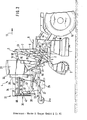
- the combination of devices according to the invention consists of a PTO-driven soil cultivator designed as a rotary harrow 1, a bottom roller 3 connected to the rotary harrow 1 via the arms 2 and a PTO-driven order machine designed as a pneumatic precision seed drill 4.
- the precision seed drill 4 is connected to the rotary harrow 1 via the coupling parts designed as lifting frames 5.
- the lifting frame 5 has the two lower links 6 and the upper link 7. With the help of the hydraulic cylinder 8, which is coupled via the line 9 to the hydraulic circuit, to which the hydraulic cylinder of the three-point linkage 10 of the tractor 11 is connected, the lifting frame 5 can be pivoted in an upright plane, so that the precision seed drill 4 can be lifted out.
- the precision seed drill 4 has the support frame 12, which consists of the cross members 14, 15 and 16 arranged transversely to the direction of travel 13.
- the cross members 14 and 15 are cross members separated in the middle, which will be explained later.
- the three-point coupling elements 17 for the connection of the lower link 6 and the three-point coupling element 18 for the connection of the upper link 7 of the lifting frame 5 are welded onto the cross member 14.
- the vertically arranged struts 19 represent the connection between the cross members 14 and 15.
- the cross member 15 extends over the entire working width of the precision seed drill 4.
- the storage container attached to the cross member 15 of the support frame 12 extends 20 for seed or fertilizer also over the entire working width of the order machine 4.
- the seed or fertilizer is supplied to the coulters 21 arranged on the cross member 14 via the seed lines 22 under the action of gravity from this storage container 20 in adjustable amounts.
- the cross members 14 and 16 are connected to one another by fastening elements, the individual precision seed drills 23 with the parallelogram-type holders 24 being each articulated on the cross member 16 so as to be movable in an upright plane.
- the height-adjustable depth guide and pressure roller 24a is arranged behind each of the precision seed drills 23.
- the single-grain sowing devices 23 each have the storage containers 26, from which the seeds located in the storage containers 26 reach the respective separating members of the precision-sowing devices 23 arranged in the housings 27.
- the seeds are separated by generating a negative pressure in the housings 27 in a known and therefore not explained manner.
- the housings 27 of the separating members are connected to the suction air blower 29 via hose lines 28.
- the respective separating members are driven by the impeller 30 of the machine 4 'via the central gear 31.
- the suction air blower 29 is screwed off-center directly behind the storage container 20 to the container rear wall 32.
- the blower 29 is driven from the tractor PTO via a countershaft transmission mounted in the rear area 33 of the ordering machine 4 on a fastening frame 34, which will be explained in more detail later.
- the mounting frame 34 is in turn attached to the reservoir 20.
- This countershaft transmission 35 is designed as a transmission gear 36 and has a large V-belt pulley 38 on the transmission input side 37 and a very much smaller V-belt pulley 40 on the transmission output side 39.
- the V-belt pulley 40 is rotatably mounted on the blower drive shaft 41 of the blower 29.
- the V-belt 42 represents the connection between the V-belt pulleys 38 and 40. With the aid of the transmission gear 36, the high speed of the fan 29 required to generate the negative pressure is achieved.
- the countershaft transmission 35 has on its transmission input side 37 the connecting pin 43 for an articulated shaft.
- the rotary harrow 1 is driven by the tractor PTO shaft via the propeller shaft 44.
- Connected to the PTO through-drive 35 of the rotary harrow gear 46 is the cardan shaft 47 driving the countershaft transmission 35, which is connected at its other end to the connecting pin 43 of the countershaft transmission 35. Since the countershaft transmission 35 for driving the fan 29 is arranged in the rear region 33 of the ordering machine 4, there is a large distance L between the PTO through-drive 45 and the connecting pin 43 of the countershaft transmission 35, that is to say that the countershaft transmission 35 is driven relatively Long cardan shaft 47.
- Lifting the order machine 4 with respect to the tillage implement 1 leads only to small and flat angles of the long cardan shaft 47, the order machine 4 having a sufficiently large, free swivel area 48 for the pivoting of the cardan shaft 47.
- This free swivel range 48 of the order machine 4 is achieved by structural measures on the precision seed drill 4 and on the lifting frame 5.
- the cross members 14 and 16 of the support frame 12 are divided in the middle both in the blower arrangement directly behind the seed or fertilizer container 20 and in the blower arrangement in the rear region 33 of the machine 4, so that there is a free passage 49 for the propeller shaft 47 .
- the components of the middle precision seed drills 23 are arranged in such a way that they do not protrude into the swivel area 48 for the swiveling of the cardan shaft 47.
- the blower 29 is arranged directly behind the storage container 30, the blower 29 is offset off-center from the central transmission gear 35.
- Container rear wall 32 of the reservoir 20 attached so that it also does not protrude into the pivoting area 48 of the propeller shaft 47.
- the strut 51 connecting the two lifting struts 50 of the lifting frame 5 is welded in such a way that it likewise does not restrict the pivoting range 48 of the drive shaft 47.
- the drive shafts 44 and 47 have practically no or only very slight angles, so that no damage to the running drive shafts 44 and 47 occurs, i.e. So that the PTO through-drive 45 of the rotary harrow gear 46 and the connecting pin 43 of the countershaft gear 35 are arranged approximately at the same height.
- the device combination is brought into the position shown in FIG. 2, which corresponds to the transport position.
- This transfer of the precision seed drill 4 into this transport position located at the very top at the front serves to shift the center of gravity of the implement combination located far behind the tractor 11 towards the tractor 11 and brings about a significant reduction in the lifting forces required when lifting the implement combination.
- FIG. 3 shows the hatched area, which shows the large, free swivel area 48 for the swiveling of the cardan shaft 47 when transferring the ordering machine 4 from the working position according to FIG. 1 to the transport or turning position according to FIG. 2.
- the hatched pivoting area 48 shows the extreme angles of the PTO shaft 47, with no angles of the PTO shaft 47 going beyond the angles specified by the PTO shaft manufacturers, so that when the precision seed drill 4 is lifted, the current PTO shaft 47 is not damaged.
- the drive of the suction air blower 29 is constantly guaranteed and ensures the vacuum required for separating the seeds, even during the turning process with the ordering machine 4 fully raised.
- the support frame 12 of the ordering machine 4 Since the countershaft transmission 35 of the blower 29 drives the propeller shaft 47 to the PTO through-drive 45 of the rotary harrow gear 46 and this PTO through-drive 45 is located at a distance a from the three-point coupling elements 17 of the lifting frame 5, it is necessary that the support frame 12 of the ordering machine 4 also is equipped with a sufficiently large, free swivel range for swiveling the propeller shaft 47.
- This large, free pivoting range for the pivoting of the propeller shaft 47 is achieved according to FIG. 4 in that the cross members 14 and 16 of the support frame 12 are divided in the middle.
- the connecting pin 43 for the connection of the propeller shaft 47 is located exactly in the middle of the machine, laterally offset from the fan drive shaft 41 of the fan 29, so that the propeller shaft 47 can move freely up and down in the central region of the ordering machine 4.
- FIG. 5 also shows a device combination consisting of a rotary harrow 1 and the precision seed drill 4 in the working position.
- This precision seeder 4 according to FIGS. 5 and 6 differs, however, by a different structural arrangement of the blower 29 and by a two-part storage container 52 for seeds or fertilizers.
- the blower 29 of this ordering machine 4 is arranged in the rear area 33 in front of the countershaft transmission 35.
- the blower 29 and the countershaft transmission 35 are held by a support arm 53 and are arranged close to one another in the machine center.
- the pivoting area 48 of the cardan shaft 47 is not impaired by the fan 29 arranged in the machine center, since it is also located in the rear area 33.
- the cross members 14 and 16 of the support frame 12 are divided in the middle for the pivoting of the cardan shaft, so that the ordering machine 4 has a sufficiently large, free swivel area 48 for the pivoting of the cardan shaft 47 and thus ensure that the ordering machine 4 is raised while the cardan shaft 47 is running , so that there is a clear shift in the center of gravity to the tractor 11 without causing damage to the propeller shaft 47 driving the fan 29.
Landscapes
- Life Sciences & Earth Sciences (AREA)
- Soil Sciences (AREA)
- Environmental Sciences (AREA)
- Engineering & Computer Science (AREA)
- Mechanical Engineering (AREA)
- Soil Working Implements (AREA)
- Fertilizing (AREA)
- Transition And Organic Metals Composition Catalysts For Addition Polymerization (AREA)
- Harvester Elements (AREA)
- Agricultural Machines (AREA)
Priority Applications (1)
| Application Number | Priority Date | Filing Date | Title |
|---|---|---|---|
| AT86105983T ATE49840T1 (de) | 1985-05-09 | 1986-04-30 | Geschlossene geraetekombination fuer die landwirtschaft. |
Applications Claiming Priority (2)
| Application Number | Priority Date | Filing Date | Title |
|---|---|---|---|
| DE3516742 | 1985-05-09 | ||
| DE19853516742 DE3516742A1 (de) | 1985-05-09 | 1985-05-09 | Geschlossene geraetekombination fuer die landwirtschaft |
Publications (2)
| Publication Number | Publication Date |
|---|---|
| EP0201048A1 true EP0201048A1 (fr) | 1986-11-12 |
| EP0201048B1 EP0201048B1 (fr) | 1990-01-31 |
Family
ID=6270292
Family Applications (1)
| Application Number | Title | Priority Date | Filing Date |
|---|---|---|---|
| EP86105983A Expired - Lifetime EP0201048B1 (fr) | 1985-05-09 | 1986-04-30 | Combinaison fermée d'instruments agricoles |
Country Status (3)
| Country | Link |
|---|---|
| EP (1) | EP0201048B1 (fr) |
| AT (1) | ATE49840T1 (fr) |
| DE (2) | DE3516742A1 (fr) |
Cited By (6)
| Publication number | Priority date | Publication date | Assignee | Title |
|---|---|---|---|---|
| EP0370984A3 (en) * | 1988-11-22 | 1990-12-27 | Frederick Murray Alexander | Agricultural seed planter |
| EP0521845A1 (fr) * | 1991-07-02 | 1993-01-07 | JANUSCHKOWETZ GmbH | Semoir mobile |
| EP0559522A1 (fr) * | 1992-02-28 | 1993-09-08 | Lely France | Outil agricole combiné constitué par l'association d'une herse et d'un semoir |
| FR2738106A1 (fr) * | 1995-08-12 | 1997-03-07 | Rauch Landmaschfab Gmbh | Appareil combine agricole constitue d'un outil de travail du sol et d'un semoir pneumatique |
| GB2534393A (en) * | 2015-01-21 | 2016-07-27 | Holme Farm Supplies Ltd | Improved apparatus for distributing agricultural product |
| EP3701780A1 (fr) * | 2019-02-28 | 2020-09-02 | Amazonen-Werke H. Dreyer GmbH & Co. KG | Système de semoir |
Families Citing this family (2)
| Publication number | Priority date | Publication date | Assignee | Title |
|---|---|---|---|---|
| DE102014000692A1 (de) * | 2014-01-15 | 2015-07-16 | Olgierd Mariusz Lemanski | Schwenkvorrichtung für eine Kombination von Saatbettbereitungseinheit und pneumatischer Sämaschine die zusammen mit einem Volldrehpflug auf eine Zugmaschine angebaut werden kann |
| CN112273008B (zh) * | 2019-07-27 | 2022-01-04 | 湖北工业大学 | 一种农业撒肥精确调节机构 |
Citations (9)
| Publication number | Priority date | Publication date | Assignee | Title |
|---|---|---|---|---|
| DE1147437B (de) * | 1958-05-20 | 1963-04-18 | J W Chafer Ltd | Staubfoerder-Vorrichtung bei Verstaeubern fuer Schaedlingsbekaempfungs- und Duengemittel |
| GB1411741A (en) * | 1971-06-14 | 1975-10-29 | Kidd Ltd Archie | Machine for distributing fertilizer |
| FR2269295A1 (fr) * | 1974-05-02 | 1975-11-28 | Lely Nv C Van Der | |
| US4047638A (en) * | 1974-10-02 | 1977-09-13 | Allis-Chalmers Corporation | Seed disc for an air planter |
| FR2371131A1 (fr) * | 1976-11-19 | 1978-06-16 | Weichel Ernst | Dispositif d'ameublissement du sol pouvant etre porte par un tracteur |
| US4148414A (en) * | 1977-12-01 | 1979-04-10 | Parks Jr Earl R | Row crop planter |
| DE3227487A1 (de) * | 1981-10-06 | 1983-04-21 | Amazonen-Werke H. Dreyer Gmbh & Co Kg, 4507 Hasbergen | Maschine zum pneumatischen ausbringen von koernigem material |
| FR2549340A1 (fr) * | 1983-07-19 | 1985-01-25 | Amazonen Werke Dreyer H | Combinaison fermee d'instruments agricoles tels qu'un outil de travail du sol et un semoir |
| GB2146213A (en) * | 1983-09-09 | 1985-04-17 | Lely Nv C Van Der | Agricultural implements |
Family Cites Families (1)
| Publication number | Priority date | Publication date | Assignee | Title |
|---|---|---|---|---|
| EP0093193B1 (fr) * | 1982-04-28 | 1986-05-28 | Maschinenfabrik Rau GmbH | Combinaison de machines agricoles |
-
1985
- 1985-05-09 DE DE19853516742 patent/DE3516742A1/de not_active Withdrawn
-
1986
- 1986-04-30 EP EP86105983A patent/EP0201048B1/fr not_active Expired - Lifetime
- 1986-04-30 AT AT86105983T patent/ATE49840T1/de not_active IP Right Cessation
- 1986-04-30 DE DE8686105983T patent/DE3668527D1/de not_active Expired - Lifetime
Patent Citations (10)
| Publication number | Priority date | Publication date | Assignee | Title |
|---|---|---|---|---|
| DE1147437B (de) * | 1958-05-20 | 1963-04-18 | J W Chafer Ltd | Staubfoerder-Vorrichtung bei Verstaeubern fuer Schaedlingsbekaempfungs- und Duengemittel |
| GB1411741A (en) * | 1971-06-14 | 1975-10-29 | Kidd Ltd Archie | Machine for distributing fertilizer |
| FR2269295A1 (fr) * | 1974-05-02 | 1975-11-28 | Lely Nv C Van Der | |
| US4047638A (en) * | 1974-10-02 | 1977-09-13 | Allis-Chalmers Corporation | Seed disc for an air planter |
| FR2371131A1 (fr) * | 1976-11-19 | 1978-06-16 | Weichel Ernst | Dispositif d'ameublissement du sol pouvant etre porte par un tracteur |
| US4148414A (en) * | 1977-12-01 | 1979-04-10 | Parks Jr Earl R | Row crop planter |
| US4148414B1 (fr) * | 1977-12-01 | 1982-09-21 | ||
| DE3227487A1 (de) * | 1981-10-06 | 1983-04-21 | Amazonen-Werke H. Dreyer Gmbh & Co Kg, 4507 Hasbergen | Maschine zum pneumatischen ausbringen von koernigem material |
| FR2549340A1 (fr) * | 1983-07-19 | 1985-01-25 | Amazonen Werke Dreyer H | Combinaison fermee d'instruments agricoles tels qu'un outil de travail du sol et un semoir |
| GB2146213A (en) * | 1983-09-09 | 1985-04-17 | Lely Nv C Van Der | Agricultural implements |
Cited By (8)
| Publication number | Priority date | Publication date | Assignee | Title |
|---|---|---|---|---|
| EP0370984A3 (en) * | 1988-11-22 | 1990-12-27 | Frederick Murray Alexander | Agricultural seed planter |
| EP0521845A1 (fr) * | 1991-07-02 | 1993-01-07 | JANUSCHKOWETZ GmbH | Semoir mobile |
| WO1993000791A1 (fr) * | 1991-07-02 | 1993-01-21 | Januschkowetz Gesellschaft M.B.H. | Semoir mobile |
| EP0559522A1 (fr) * | 1992-02-28 | 1993-09-08 | Lely France | Outil agricole combiné constitué par l'association d'une herse et d'un semoir |
| FR2738106A1 (fr) * | 1995-08-12 | 1997-03-07 | Rauch Landmaschfab Gmbh | Appareil combine agricole constitue d'un outil de travail du sol et d'un semoir pneumatique |
| GB2534393A (en) * | 2015-01-21 | 2016-07-27 | Holme Farm Supplies Ltd | Improved apparatus for distributing agricultural product |
| GB2534393B (en) * | 2015-01-21 | 2021-04-14 | Holme Farm Supplies Ltd | Improved apparatus for distributing agricultural product |
| EP3701780A1 (fr) * | 2019-02-28 | 2020-09-02 | Amazonen-Werke H. Dreyer GmbH & Co. KG | Système de semoir |
Also Published As
| Publication number | Publication date |
|---|---|
| DE3668527D1 (de) | 1990-03-08 |
| EP0201048B1 (fr) | 1990-01-31 |
| ATE49840T1 (de) | 1990-02-15 |
| DE3516742A1 (de) | 1986-11-13 |
Similar Documents
| Publication | Publication Date | Title |
|---|---|---|
| DE2534596A1 (de) | Bodenbearbeitungsmaschine | |
| DE3752251T2 (de) | Bodenbearbeitungsgerät | |
| EP0201048B1 (fr) | Combinaison fermée d'instruments agricoles | |
| DE69325166T2 (de) | Kombination eines drehpfluges und eines gerätes zur saatbettbereitung | |
| DE2741373A1 (de) | Bodenbearbeitungsmaschine | |
| DE68903856T3 (de) | Mechanisch angetriebenes Bodenbearbeitungsgerät. | |
| DE2622649C2 (de) | Schlepperbetriebene Bodenbearbeitungsmaschine | |
| EP0310856A2 (fr) | Combinaisons de culture et de semis | |
| DE3436123A1 (de) | Bodenbearbeitungsmaschine, insbesondere kreiselegge | |
| DE69420316T2 (de) | Sämaschine mit einer Vorrichtung zur Begrenzung der Tiefe von Säscharen im Boden, und eine kombinierte Landmaschine bestehend aus einer Bodenbearbeitungsmaschine und eine Sämaschine mit Verwendung einer solcher Sämaschine | |
| CH622666A5 (en) | Working appliance for ground loosening which can be mounted on a tractor | |
| DE19954423A1 (de) | Landwirtschaftliche Bestellkombination mit günstiger Schwerpunktsverlagerung | |
| DE2735366A1 (de) | Anhaengevorrichtung fuer landmaschinen | |
| DE4002172C1 (en) | Agricultural implement for preparing soil - has self propelled vehicle with platform which has movable working arm | |
| DE102017115929A1 (de) | Gezogenes landwirtschaftliches Arbeitsgerät mit kraftbetriebenen Bodenbearbeitungs- und/oder Säelementen | |
| DE19833674A1 (de) | Aufgesattelte Kreiselegge | |
| EP0201049B1 (fr) | Semoir pneumatique monograine | |
| DE69421954T2 (de) | Landwirtschaftliche Bodenbearbeitungsmaschine mit grosser Breite, die sich besser an die Bodenunebenheit anpasst | |
| DE8513763U1 (de) | Geschlossene Gerätekombination für die Landwirtschaft | |
| GB2147186A (en) | An agricultural tractor | |
| DE69424828T2 (de) | Gerätekombination zur Bodenbearbeitung und zum Säen deren Sämaschine während des Transportes gut gehalten ist | |
| DE69407113T2 (de) | Pneumatischer Sämaschine und kombinierte Landmaschine zur Bodenbearbeitung und zum Säen mit einer solchen pneumatischen Sämaschine | |
| EP0459175A1 (fr) | Machine agricole avec une combinaison d'ustensiles | |
| DE841522C (de) | Landwirtschaftliches motorisiertes Mehrzweckgeraet | |
| DE3342025A1 (de) | Schlepper |
Legal Events
| Date | Code | Title | Description |
|---|---|---|---|
| PUAI | Public reference made under article 153(3) epc to a published international application that has entered the european phase |
Free format text: ORIGINAL CODE: 0009012 |
|
| AK | Designated contracting states |
Kind code of ref document: A1 Designated state(s): AT BE CH DE FR GB IT LI LU NL SE |
|
| 17P | Request for examination filed |
Effective date: 19861001 |
|
| 17Q | First examination report despatched |
Effective date: 19871210 |
|
| GRAA | (expected) grant |
Free format text: ORIGINAL CODE: 0009210 |
|
| AK | Designated contracting states |
Kind code of ref document: B1 Designated state(s): AT BE CH DE FR GB IT LI LU NL SE |
|
| PG25 | Lapsed in a contracting state [announced via postgrant information from national office to epo] |
Ref country code: IT Free format text: LAPSE BECAUSE OF FAILURE TO SUBMIT A TRANSLATION OF THE DESCRIPTION OR TO PAY THE FEE WITHIN THE PRE;WARNING: LAPSES OF ITALIAN PATENTS WITH EFFECTIVE DATE BEFORE 2007 MAY HAVE OCCURRED AT ANY TIME BEFORE 2007. THE CORRECT EFFECTIVE DATE MAY BE DIFFERENT FROM THE ONE RECORDED.SCRIBED TIME-LIMIT Effective date: 19900131 Ref country code: BE Effective date: 19900131 Ref country code: NL Effective date: 19900131 Ref country code: SE Effective date: 19900131 |
|
| REF | Corresponds to: |
Ref document number: 49840 Country of ref document: AT Date of ref document: 19900215 Kind code of ref document: T |
|
| ET | Fr: translation filed | ||
| REF | Corresponds to: |
Ref document number: 3668527 Country of ref document: DE Date of ref document: 19900308 |
|
| PG25 | Lapsed in a contracting state [announced via postgrant information from national office to epo] |
Ref country code: LU Free format text: LAPSE BECAUSE OF NON-PAYMENT OF DUE FEES Effective date: 19900430 Ref country code: LI Effective date: 19900430 Ref country code: CH Effective date: 19900430 Ref country code: AT Effective date: 19900430 |
|
| GBT | Gb: translation of ep patent filed (gb section 77(6)(a)/1977) | ||
| NLV1 | Nl: lapsed or annulled due to failure to fulfill the requirements of art. 29p and 29m of the patents act | ||
| PLBI | Opposition filed |
Free format text: ORIGINAL CODE: 0009260 |
|
| 26 | Opposition filed |
Opponent name: RABEWERK GMBH + CO. Effective date: 19900816 |
|
| REG | Reference to a national code |
Ref country code: CH Ref legal event code: PL |
|
| PGFP | Annual fee paid to national office [announced via postgrant information from national office to epo] |
Ref country code: GB Payment date: 19930325 Year of fee payment: 8 |
|
| PGFP | Annual fee paid to national office [announced via postgrant information from national office to epo] |
Ref country code: FR Payment date: 19930406 Year of fee payment: 8 |
|
| PLBN | Opposition rejected |
Free format text: ORIGINAL CODE: 0009273 |
|
| STAA | Information on the status of an ep patent application or granted ep patent |
Free format text: STATUS: OPPOSITION REJECTED |
|
| PG25 | Lapsed in a contracting state [announced via postgrant information from national office to epo] |
Ref country code: GB Effective date: 19940430 |
|
| PGFP | Annual fee paid to national office [announced via postgrant information from national office to epo] |
Ref country code: DE Payment date: 19940530 Year of fee payment: 9 |
|
| 27O | Opposition rejected |
Effective date: 19940321 |
|
| PG25 | Lapsed in a contracting state [announced via postgrant information from national office to epo] |
Ref country code: FR Effective date: 19941229 |
|
| GBPC | Gb: european patent ceased through non-payment of renewal fee |
Effective date: 19940430 |
|
| REG | Reference to a national code |
Ref country code: FR Ref legal event code: ST |
|
| PG25 | Lapsed in a contracting state [announced via postgrant information from national office to epo] |
Ref country code: DE Effective date: 19960103 |
|
| APAH | Appeal reference modified |
Free format text: ORIGINAL CODE: EPIDOSCREFNO |