EP0201050A2 - Générateur de vibrations à plusieurs balourds dans un carter, en particulier pour des convoyeurs vibrants utilisés dans les exploitations minières - Google Patents
Générateur de vibrations à plusieurs balourds dans un carter, en particulier pour des convoyeurs vibrants utilisés dans les exploitations minières Download PDFInfo
- Publication number
- EP0201050A2 EP0201050A2 EP86106000A EP86106000A EP0201050A2 EP 0201050 A2 EP0201050 A2 EP 0201050A2 EP 86106000 A EP86106000 A EP 86106000A EP 86106000 A EP86106000 A EP 86106000A EP 0201050 A2 EP0201050 A2 EP 0201050A2
- Authority
- EP
- European Patent Office
- Prior art keywords
- unbalance
- shaft
- unbalances
- vibration
- housing
- Prior art date
- Legal status (The legal status is an assumption and is not a legal conclusion. Google has not performed a legal analysis and makes no representation as to the accuracy of the status listed.)
- Ceased
Links
- 238000005065 mining Methods 0.000 title 1
- 230000008859 change Effects 0.000 claims description 5
- 241000273930 Brevoortia tyrannus Species 0.000 description 7
- 230000008901 benefit Effects 0.000 description 2
- 230000000694 effects Effects 0.000 description 2
- 230000009286 beneficial effect Effects 0.000 description 1
- 239000003245 coal Substances 0.000 description 1
- 230000001419 dependent effect Effects 0.000 description 1
- 238000000605 extraction Methods 0.000 description 1
- 230000005484 gravity Effects 0.000 description 1
- 230000006872 improvement Effects 0.000 description 1
- 239000000463 material Substances 0.000 description 1
- 230000007246 mechanism Effects 0.000 description 1
- 238000000034 method Methods 0.000 description 1
- 230000008569 process Effects 0.000 description 1
- 238000007789 sealing Methods 0.000 description 1
- 239000007787 solid Substances 0.000 description 1
- 239000013589 supplement Substances 0.000 description 1
Images
Classifications
-
- B—PERFORMING OPERATIONS; TRANSPORTING
- B06—GENERATING OR TRANSMITTING MECHANICAL VIBRATIONS IN GENERAL
- B06B—METHODS OR APPARATUS FOR GENERATING OR TRANSMITTING MECHANICAL VIBRATIONS OF INFRASONIC, SONIC, OR ULTRASONIC FREQUENCY, e.g. FOR PERFORMING MECHANICAL WORK IN GENERAL
- B06B1/00—Methods or apparatus for generating mechanical vibrations of infrasonic, sonic, or ultrasonic frequency
- B06B1/10—Methods or apparatus for generating mechanical vibrations of infrasonic, sonic, or ultrasonic frequency making use of mechanical energy
- B06B1/16—Methods or apparatus for generating mechanical vibrations of infrasonic, sonic, or ultrasonic frequency making use of mechanical energy operating with systems involving rotary unbalanced masses
- B06B1/161—Adjustable systems, i.e. where amplitude or direction of frequency of vibration can be varied
- B06B1/166—Where the phase-angle of masses mounted on counter-rotating shafts can be varied, e.g. variation of the vibration phase
Definitions
- the invention relates to a vibration exciter with a plurality of unbalances in a housing according to the preamble of claim 1.
- the invention relates in particular to vibration exciters for vibrating conveyor troughs in underground operations.
- such vibratory conveyor troughs serve as extraction devices under bunkers, which in the main or in the bypass one via continuous conveyors, e.g. Conveyor belts are continuously arranged to extract coal, more rarely from mountains.
- bunkers serve as temporary storage if the conveying capacity of the continuous conveyors is insufficient to cope with the conveyed volume.
- the vibrating conveyor trough is then arranged in the outlet of the bunker and serves as a feeder for a downstream continuous conveyor and as a bunker closure.
- the vibration exciter is usually attached to the rear crossmember of the vibrating trough.
- the invention therefore relates to a vibration exciter which can be designed for high performance.
- Such vibration exciters generate the vibration energy by an electric motor.
- the direction of vibration is horizontal at a certain swing angle.
- a reciprocating process is advantageous.
- Vibration exciters driven by an electric motor make it possible to meet practically any performance requirements.
- the conveying effect in a vibrating trough then occurs in that the unbalances, which are usually formed by eccentric disks, and the vibrating trough carry out rectilinear and mutually directed oscillating movements with the weight of the electromotive drive and the housing of the vibration exciter.
- Electromagnetic vibration exciters can be easily and continuously controlled. This makes it possible to control and regulate the flow of the conveyed material running over the vibrating trough during operation.
- a control system can include a belt position, which is arranged in front of the bunker outlet and adjusts the bunker discharge in inverse proportion to the amount conveyed on the belt.
- the limited performance of the electromagnetic vibration exciter has so far prevented such controls or regulations from being used in corresponding applications of underground operations.
- the invention is based on a vibration exciter with an electric motor drive (DE-PS 29 09 204).
- one of the unbalances is fixed on its unbalanced shaft; a second unbalance is pivotally mounted on its unbalanced shaft.
- the unbalance can therefore only be controlled with a correspondingly low effect.
- the shaft of the pivotable unbalance is designed for adjustment during operation as a cylinder of a hydraulic servomotor, the piston of which engages with a pin in a spiral groove of a stub shaft and thereby changes the eccentricity of the unbalanced mass depending on the pressure applied. Since the cylinder opening is located in a pressure chamber fixed to the housing, the adjustment can be brought about independently of the rotational movement of the unbalanced shaft.
- the invention has for its object to provide an electric motor-driven vibration exciter of the type presupposed as known so that the chamfer position of the unbalance can be adjusted effectively and in a simple manner regardless of the speed of the unbalanced shaft and the size of the unbalanced masses continuously and practically without inertia.
- the adjustment gear required for this is a mechanical gear, the components and bearings of which can be adapted to the stresses during operation of the vibration exciter.
- These are the entrained hollow shafts, which act as connecting links in the kinematic chain extending from an adjuster located outside the housing and form the input of the toothed gear with which the eccentricity of the concerned one Unbalance is changed.
- the invention has the advantage that the slider can be adjusted by an actuator arranged outside the housing, which forms the prerequisite for a step-free and inertia-free adjustment of the 'eccentricity of the unbalance during operation. Since the adjusting mechanism is practically self-locking overall, each eccentricity once set is held by the servomotor and is therefore not easily exposed to unpredictable changes during operation. You can also change the eccentricity in the same way during breaks when you operate the actuator accordingly. In many cases, however, it may be beneficial to exclude the arbitrary intervention from outside. Among other things therefore, under such circumstances, the motorized adjustment is preferred to the manual adjustment that is also possible according to the invention.
- the eccentricity of the unbalance is changed by pivoting, whereby the eccentricity of the center of gravity of the unbalance is adjusted. This results in a further improvement in the fine adjustment.
- the features of claim 5 make it possible to pre-set the dimensions and the eccentricity of the unbalances during breaks in operation, bypassing the adjustment gear. This makes it possible to start with a change in the eccentricity of the unbalance during operation from a preselected value which results from the respective operating conditions.
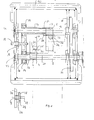
- the vibration exciter shown in FIG. 1, generally designated 1, has several unbalances 2, 3, which are shown in their extreme positions in the illustration in FIG. 1.
- Modified bevel lag can be identified by two unbalanced representations on each imbalance.
- the imbalances are housed in a housing, generally designated 42.
- the drive takes place via a clutch 3 by an electric motor, wherein a cardan shaft can be connected between the clutch 3 and the motor shaft in order to set up the motor outside the oscillating system.
- the vibration exciter shown is suitable for use on the crossbar of a vibratory conveyor of underground operations, which, as explained at the beginning, forms the closure and the discharge of a bunker.
- the two imbalances 2, 3 are arranged in different vertical planes, but otherwise in a corresponding manner. They are seated on a hub 4, 5, which in turn is fixed with a radially arranged grub screw 6 or 7 on a solid shaft 8 or 9 in a rotationally and thrust-resistant manner.
- the shafts 8, 9 serve as unbalance shafts, which cause the unbalances 2, 3 to rotate via the hubs 4, 5.
- the shafts are coupled with a spur gear 10, 11 and with the same Speed driven.
- Each unbalanced shaft 8, 9 has a hollow shaft 12, 13 concentrically on the outside. Each hollow shaft is seated in a roller bearing 14, 15 of a slide 16. The hollow shafts 12, 13 are thus mounted in the slide 16 in a thrust-resistant manner. As a result of the arrangement of the two unbalances 2, 3 in planes lying next to one another, the hollow shaft 13, which is assigned to the unbalanced shaft 9 of the unbalanced mass 2, is mounted on a slide bearing 17 opposite the shaft 9. This is due to the fact that the hollow shaft 13 is longer than the hollow shaft 12 because the unbalance 2 is further away from the slide 16 than the unbalance 4. Both hollow shafts therefore guide the disc-shaped body of the slide when it is moved.
- the slider 16 can be moved with the aid of a spindle 18, which can be rotated via a shaft 19 by a handwheel (not shown) or via an actuator, parallel to the unbalanced shafts 8, 9 or the hollow shafts 12, 13 described.
- a spindle 18 On the ends of the hollow shafts there are toothed racks 20, 21 which mesh with pinions 22, 23 which are arranged in a rotationally fixed manner on articulated shafts 24, 25 of swivel joints 26, 27.
- the rotatable part of the rotary joints 26, 27 is formed by the unbalances 2, 3.
- the geometrical axes of the rotary joints run perpendicular to the geometrical axes of the shafts 8, 9 and 12, 13.
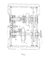
- an arrangement for adjusting the slide 16 is shown, which is mainly considered for the electromotive drive of the slide 16.
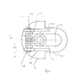
- the two shafts are each supported in a bearing 37, 38 and 39, 40 at both ends and provided at one end with a projection 41, 42 which has key surfaces.
- a correspondingly designed recess in the shafts 8, 9 receives the projections 41 and 42 in a form-fitting manner when the front housing 32 is screwed to the housing 2. These recesses are normally closed with lids 43, 44.
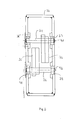
- each imbalance 2, 3 carries two guide strips 60, which form a link guide for a projection 61 in which the elongated hole 59 is recessed.
- the fixed part of the link guide is formed by the respective hub 4, 5.
- Worm wheel 28 which is driven by means of a worm 29 on a worm shaft 30.
- the worm shaft 30 is led out of the housing.
- the shaft 19 is therefore mounted in the end wall 31 of the housing.
- the unbalance shaft 8 is rotated via the clutch 3, as a result of which the unbalanced shaft 9 also rotates with the unbalanced shaft 8 as a result of its connection by the additional gear 10, 11. If the unbalances are in the position shown with solid lines, their eccentricity reaches their maximum. As soon as the spindle 18 is rotated via the shaft 19, the slide 16 is axially displaced and takes the hollow shafts 12, 13 with it. As a result, the racks 20, 21 move relative to the pinions 22, 23 of the rotary joints 26, 27, as a result of which the unbalances 2, 3 are pivoted. This change reduces the eccentricity of the unbalances 2, 3 and thus the desired vibration.
- the vibration exciter 1 can be used in the context of a control system which changes the delivery rate of the vibration channel via the worm shaft 30 by an electric motor.
- the unbalanced masses can be preset.
- the unbalance 33 supplements the unbalance 2 via its shaft 34, while the unbalance 35
Landscapes
- Engineering & Computer Science (AREA)
- Mechanical Engineering (AREA)
- Jigging Conveyors (AREA)
- Apparatuses For Generation Of Mechanical Vibrations (AREA)
Applications Claiming Priority (2)
| Application Number | Priority Date | Filing Date | Title |
|---|---|---|---|
| DE19853516145 DE3516145A1 (de) | 1985-05-04 | 1985-05-04 | Schwingungserreger mit mehreren unwuchten in einem gehaeuse, insbesondere fuer schwingfoerderrinnen des untertagebetriebes |
| DE3516145 | 1985-05-04 |
Publications (2)
| Publication Number | Publication Date |
|---|---|
| EP0201050A2 true EP0201050A2 (fr) | 1986-11-12 |
| EP0201050A3 EP0201050A3 (fr) | 1987-08-26 |
Family
ID=6269890
Family Applications (1)
| Application Number | Title | Priority Date | Filing Date |
|---|---|---|---|
| EP86106000A Ceased EP0201050A3 (fr) | 1985-05-04 | 1986-05-01 | Générateur de vibrations à plusieurs balourds dans un carter, en particulier pour des convoyeurs vibrants utilisés dans les exploitations minières |
Country Status (2)
| Country | Link |
|---|---|
| EP (1) | EP0201050A3 (fr) |
| DE (1) | DE3516145A1 (fr) |
Cited By (2)
| Publication number | Priority date | Publication date | Assignee | Title |
|---|---|---|---|---|
| EP0406480A3 (en) * | 1989-07-06 | 1991-12-11 | Mueller Gmbh Herne Pumpen, Maschinen, Stahlbau | Vibrator with rotating masses |
| FR2667517A1 (fr) * | 1990-10-09 | 1992-04-10 | Lm Electronique | Dispositif de vibration. |
Families Citing this family (3)
| Publication number | Priority date | Publication date | Assignee | Title |
|---|---|---|---|---|
| DE8800592U1 (de) * | 1988-01-20 | 1988-03-10 | Rhein-Getriebe Gmbh, 4005 Meerbusch | Rüttelgetriebe |
| US6769838B2 (en) | 2001-10-31 | 2004-08-03 | Caterpillar Paving Products Inc | Variable vibratory mechanism |
| CN101837341B (zh) * | 2009-03-14 | 2012-01-11 | 李卓 | 一种激振器 |
Family Cites Families (8)
| Publication number | Priority date | Publication date | Assignee | Title |
|---|---|---|---|---|
| BE622582A (fr) * | 1961-09-18 | |||
| GB1048612A (en) * | 1963-01-25 | 1966-11-16 | Gen Mills Inc | Variable thrust oscillator |
| DE1483409B2 (de) * | 1965-03-06 | 1971-12-30 | Ing. Otto Schwarz Maschinenbau, 8710 Kitzingen | Ruettelmotor |
| FR1512553A (fr) * | 1966-12-29 | 1968-02-09 | Strasbourg Forges | Perfectionnements apportés au réglage des appareils vibratoires |
| CH476379A (de) * | 1968-11-15 | 1969-07-31 | Sprecher & Schuh Ag | Metallgekapselte gasisolierte Hochspannungsleitung |
| GB1374517A (en) * | 1972-03-23 | 1974-11-20 | Simonacco Ltd | Vibrating devices |
| DE2736264A1 (de) * | 1977-08-11 | 1979-03-01 | Schlosser & Co Gmbh | Schwingungserreger, insbesondere fuer verdichtungsruettler |
| DE2909204C2 (de) * | 1979-03-09 | 1982-08-19 | Wacker-Werke Gmbh & Co Kg, 8077 Reichertshofen | Schwingungserreger mit zwei Unwuchten |
-
1985
- 1985-05-04 DE DE19853516145 patent/DE3516145A1/de not_active Ceased
-
1986
- 1986-05-01 EP EP86106000A patent/EP0201050A3/fr not_active Ceased
Cited By (2)
| Publication number | Priority date | Publication date | Assignee | Title |
|---|---|---|---|---|
| EP0406480A3 (en) * | 1989-07-06 | 1991-12-11 | Mueller Gmbh Herne Pumpen, Maschinen, Stahlbau | Vibrator with rotating masses |
| FR2667517A1 (fr) * | 1990-10-09 | 1992-04-10 | Lm Electronique | Dispositif de vibration. |
Also Published As
| Publication number | Publication date |
|---|---|
| DE3516145A1 (de) | 1986-11-06 |
| EP0201050A3 (fr) | 1987-08-26 |
Similar Documents
| Publication | Publication Date | Title |
|---|---|---|
| DE3002449C2 (fr) | ||
| DE2744903A1 (de) | Kraftgetriebene gelenkverbindung | |
| DE68903494T2 (de) | Maschine zum schneiden von granitblock- oder steinmaterialien in platten. | |
| EP0802879A1 (fr) | Dispositif pour doser des produits en vrac | |
| EP1476251B1 (fr) | Broyeur a machoires pourvu d'un arbre de commande traversant | |
| EP0780164A2 (fr) | Vibrateur à action dirigée | |
| DE4314632A1 (de) | Fördereinrichtung für Gegenstände in Verpackungsmaschinen, insbesondere für Faltschachteln | |
| EP0201050A2 (fr) | Générateur de vibrations à plusieurs balourds dans un carter, en particulier pour des convoyeurs vibrants utilisés dans les exploitations minières | |
| EP2380700A2 (fr) | Rectifieuse à portique | |
| DE4135395A1 (de) | Zellenradschleuse | |
| DE3105083C2 (de) | "Vorschubeinrichtung für Holzbearbeitungsmaschinen" | |
| DE19962475C2 (de) | Verfahren und Vorrichtung zur Befüllung eines Sackes | |
| DE202008013097U1 (de) | Rotierende Füllmaschine | |
| DE2843757A1 (de) | Schleifwerkzeug mit geradlinig bewegtem schleifschuh und ausgleichendem gegengewicht | |
| EP0406480B1 (fr) | Vibrateur à masses tournantes | |
| DE2605313A1 (de) | Vorrichtung zum mechanischen auflockern und zufuehren von schwerfliessenden schuettguetern | |
| DE2729057C3 (de) | Schnecke zum Fördern abgeschiedenen Feststoffes in einer Zentrifuge | |
| DE3322676A1 (de) | Vorrichtung zur durchfuehrung einer automatischen schweissung laengs einer komplizierten kontur | |
| EP3572145B1 (fr) | Dispositif et procédé d'homogénéisation des substances coulantes | |
| DE3006927C2 (de) | Kreissäge | |
| DE3542989C2 (fr) | ||
| DE3151239C2 (de) | Vorrichtung zum Einleiten einer Axialbewegung in die Messerwelle einer Plissiermaschine | |
| DE10212418B4 (de) | Vorrichtung zum Beschicken einer Förderschnecke | |
| DE1483409C (de) | Ruttelmotor | |
| DE29814921U1 (de) | Vorrichtung zum Kompaktieren, mit verstellbarem Stator |
Legal Events
| Date | Code | Title | Description |
|---|---|---|---|
| PUAI | Public reference made under article 153(3) epc to a published international application that has entered the european phase |
Free format text: ORIGINAL CODE: 0009012 |
|
| AK | Designated contracting states |
Kind code of ref document: A2 Designated state(s): BE DE GB |
|
| PUAL | Search report despatched |
Free format text: ORIGINAL CODE: 0009013 |
|
| 17P | Request for examination filed |
Effective date: 19870501 |
|
| AK | Designated contracting states |
Kind code of ref document: A3 Designated state(s): BE DE GB |
|
| 17Q | First examination report despatched |
Effective date: 19890518 |
|
| STAA | Information on the status of an ep patent application or granted ep patent |
Free format text: STATUS: THE APPLICATION HAS BEEN REFUSED |
|
| 18R | Application refused |
Effective date: 19891229 |
|
| RIN1 | Information on inventor provided before grant (corrected) |
Inventor name: HAAKE, HEINRICH |