EP0201052A2 - Procédé pour la production d'un fourrage pelletisé et appareil pour la réalisation du procédé - Google Patents
Procédé pour la production d'un fourrage pelletisé et appareil pour la réalisation du procédé Download PDFInfo
- Publication number
- EP0201052A2 EP0201052A2 EP86106016A EP86106016A EP0201052A2 EP 0201052 A2 EP0201052 A2 EP 0201052A2 EP 86106016 A EP86106016 A EP 86106016A EP 86106016 A EP86106016 A EP 86106016A EP 0201052 A2 EP0201052 A2 EP 0201052A2
- Authority
- EP
- European Patent Office
- Prior art keywords
- die
- pressure
- feed
- pelletizer
- press
- Prior art date
- Legal status (The legal status is an assumption and is not a legal conclusion. Google has not performed a legal analysis and makes no representation as to the accuracy of the status listed.)
- Granted
Links
- 238000000034 method Methods 0.000 title claims abstract description 17
- 230000008569 process Effects 0.000 title claims description 10
- 238000004519 manufacturing process Methods 0.000 title claims description 3
- 239000004466 pelleted feed Substances 0.000 title description 2
- 238000005453 pelletization Methods 0.000 claims abstract description 14
- 239000000463 material Substances 0.000 claims description 101
- 239000008188 pellet Substances 0.000 claims description 66
- 238000003825 pressing Methods 0.000 claims description 14
- 238000012372 quality testing Methods 0.000 claims description 6
- 238000005096 rolling process Methods 0.000 claims description 2
- 239000007858 starting material Substances 0.000 abstract description 3
- 238000013461 design Methods 0.000 description 11
- 230000000694 effects Effects 0.000 description 8
- 239000000047 product Substances 0.000 description 7
- 238000010276 construction Methods 0.000 description 5
- 238000005259 measurement Methods 0.000 description 4
- 238000010586 diagram Methods 0.000 description 3
- 238000009826 distribution Methods 0.000 description 3
- 239000012634 fragment Substances 0.000 description 3
- 238000002156 mixing Methods 0.000 description 3
- 230000004048 modification Effects 0.000 description 3
- 238000012986 modification Methods 0.000 description 3
- 238000003892 spreading Methods 0.000 description 3
- 230000007480 spreading Effects 0.000 description 3
- 230000009471 action Effects 0.000 description 2
- 230000003321 amplification Effects 0.000 description 2
- 230000004323 axial length Effects 0.000 description 2
- 238000006243 chemical reaction Methods 0.000 description 2
- 239000007795 chemical reaction product Substances 0.000 description 2
- 238000001816 cooling Methods 0.000 description 2
- 230000006872 improvement Effects 0.000 description 2
- 239000011159 matrix material Substances 0.000 description 2
- 238000003199 nucleic acid amplification method Methods 0.000 description 2
- 239000002994 raw material Substances 0.000 description 2
- 238000012360 testing method Methods 0.000 description 2
- 229920002472 Starch Polymers 0.000 description 1
- 229910000831 Steel Inorganic materials 0.000 description 1
- 238000005299 abrasion Methods 0.000 description 1
- 238000009825 accumulation Methods 0.000 description 1
- 230000001154 acute effect Effects 0.000 description 1
- 230000002411 adverse Effects 0.000 description 1
- 230000008901 benefit Effects 0.000 description 1
- 238000005056 compaction Methods 0.000 description 1
- 230000001143 conditioned effect Effects 0.000 description 1
- 230000003750 conditioning effect Effects 0.000 description 1
- 238000011109 contamination Methods 0.000 description 1
- 230000001627 detrimental effect Effects 0.000 description 1
- 230000029087 digestion Effects 0.000 description 1
- 238000005315 distribution function Methods 0.000 description 1
- 238000011156 evaluation Methods 0.000 description 1
- 230000002349 favourable effect Effects 0.000 description 1
- 239000007788 liquid Substances 0.000 description 1
- 239000000203 mixture Substances 0.000 description 1
- 239000002245 particle Substances 0.000 description 1
- 238000005192 partition Methods 0.000 description 1
- 230000002093 peripheral effect Effects 0.000 description 1
- 238000004064 recycling Methods 0.000 description 1
- 230000009467 reduction Effects 0.000 description 1
- 230000001105 regulatory effect Effects 0.000 description 1
- 230000035945 sensitivity Effects 0.000 description 1
- 238000005549 size reduction Methods 0.000 description 1
- 235000019698 starch Nutrition 0.000 description 1
- 239000008107 starch Substances 0.000 description 1
- 239000010959 steel Substances 0.000 description 1
- 230000001954 sterilising effect Effects 0.000 description 1
- 238000004659 sterilization and disinfection Methods 0.000 description 1
- 239000000126 substance Substances 0.000 description 1
- 238000011144 upstream manufacturing Methods 0.000 description 1
Images



Classifications
-
- B—PERFORMING OPERATIONS; TRANSPORTING
- B30—PRESSES
- B30B—PRESSES IN GENERAL
- B30B11/00—Presses specially adapted for forming shaped articles from material in particulate or plastic state, e.g. briquetting presses, tabletting presses
- B30B11/20—Roller-and-ring machines, i.e. with roller disposed within a ring and co-operating with the inner surface of the ring
- B30B11/201—Roller-and-ring machines, i.e. with roller disposed within a ring and co-operating with the inner surface of the ring for extruding material
-
- A—HUMAN NECESSITIES
- A23—FOODS OR FOODSTUFFS; TREATMENT THEREOF, NOT COVERED BY OTHER CLASSES
- A23K—FODDER
- A23K40/00—Shaping or working-up of animal feeding-stuffs
- A23K40/20—Shaping or working-up of animal feeding-stuffs by moulding, e.g. making cakes or briquettes
-
- A—HUMAN NECESSITIES
- A23—FOODS OR FOODSTUFFS; TREATMENT THEREOF, NOT COVERED BY OTHER CLASSES
- A23N—MACHINES OR APPARATUS FOR TREATING HARVESTED FRUIT, VEGETABLES OR FLOWER BULBS IN BULK, NOT OTHERWISE PROVIDED FOR; PEELING VEGETABLES OR FRUIT IN BULK; APPARATUS FOR PREPARING ANIMAL FEEDING- STUFFS
- A23N17/00—Apparatus specially adapted for preparing animal feeding-stuffs
- A23N17/005—Apparatus specially adapted for preparing animal feeding-stuffs for shaping by moulding, extrusion, pressing, e.g. pellet-mills
-
- B—PERFORMING OPERATIONS; TRANSPORTING
- B30—PRESSES
- B30B—PRESSES IN GENERAL
- B30B11/00—Presses specially adapted for forming shaped articles from material in particulate or plastic state, e.g. briquetting presses, tabletting presses
- B30B11/005—Control arrangements
-
- B—PERFORMING OPERATIONS; TRANSPORTING
- B30—PRESSES
- B30B—PRESSES IN GENERAL
- B30B11/00—Presses specially adapted for forming shaped articles from material in particulate or plastic state, e.g. briquetting presses, tabletting presses
- B30B11/20—Roller-and-ring machines, i.e. with roller disposed within a ring and co-operating with the inner surface of the ring
- B30B11/201—Roller-and-ring machines, i.e. with roller disposed within a ring and co-operating with the inner surface of the ring for extruding material
- B30B11/202—Ring constructions
-
- B—PERFORMING OPERATIONS; TRANSPORTING
- B30—PRESSES
- B30B—PRESSES IN GENERAL
- B30B11/00—Presses specially adapted for forming shaped articles from material in particulate or plastic state, e.g. briquetting presses, tabletting presses
- B30B11/20—Roller-and-ring machines, i.e. with roller disposed within a ring and co-operating with the inner surface of the ring
- B30B11/201—Roller-and-ring machines, i.e. with roller disposed within a ring and co-operating with the inner surface of the ring for extruding material
- B30B11/207—Feed means
-
- B—PERFORMING OPERATIONS; TRANSPORTING
- B29—WORKING OF PLASTICS; WORKING OF SUBSTANCES IN A PLASTIC STATE IN GENERAL
- B29B—PREPARATION OR PRETREATMENT OF THE MATERIAL TO BE SHAPED; MAKING GRANULES OR PREFORMS; RECOVERY OF PLASTICS OR OTHER CONSTITUENTS OF WASTE MATERIAL CONTAINING PLASTICS
- B29B9/00—Making granules
- B29B9/02—Making granules by dividing preformed material
- B29B9/06—Making granules by dividing preformed material in the form of filamentary material, e.g. combined with extrusion
-
- Y—GENERAL TAGGING OF NEW TECHNOLOGICAL DEVELOPMENTS; GENERAL TAGGING OF CROSS-SECTIONAL TECHNOLOGIES SPANNING OVER SEVERAL SECTIONS OF THE IPC; TECHNICAL SUBJECTS COVERED BY FORMER USPC CROSS-REFERENCE ART COLLECTIONS [XRACs] AND DIGESTS
- Y10—TECHNICAL SUBJECTS COVERED BY FORMER USPC
- Y10S—TECHNICAL SUBJECTS COVERED BY FORMER USPC CROSS-REFERENCE ART COLLECTIONS [XRACs] AND DIGESTS
- Y10S100/00—Presses
- Y10S100/903—Pelleters
- Y10S100/905—Pelleters inner roll
-
- Y—GENERAL TAGGING OF NEW TECHNOLOGICAL DEVELOPMENTS; GENERAL TAGGING OF CROSS-SECTIONAL TECHNOLOGIES SPANNING OVER SEVERAL SECTIONS OF THE IPC; TECHNICAL SUBJECTS COVERED BY FORMER USPC CROSS-REFERENCE ART COLLECTIONS [XRACs] AND DIGESTS
- Y10—TECHNICAL SUBJECTS COVERED BY FORMER USPC
- Y10S—TECHNICAL SUBJECTS COVERED BY FORMER USPC CROSS-REFERENCE ART COLLECTIONS [XRACs] AND DIGESTS
- Y10S366/00—Agitating
- Y10S366/603—Animal food mixer
Definitions
- the invention relates to a method for producing a pelleted feed by pelleting its components under pressure.
- feed should be understood to mean any means suitable for feeding if it may also be used for another purpose, for example as a starting material for a chemical product.
- the invention is based on the object of improving a method of the type mentioned at the outset, and this is achieved according to the invention in that the pelletized product obtained is treated at least partially on a pressure pelletizer at least one more time.
- This method can then be carried out either by a device which is characterized in that a feed arrangement, in particular a return arrangement, is provided for the pelletized material for a further pelleting process within a single pressure pelletizer, or by a device in which a feed arrangement starts a preceding pelletizer leads to the input of a downstream pelletizer. Further details of the invention result from the following description of exemplary embodiments shown schematically in the drawing.
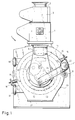
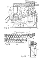
- the material to be pelletized in a pellet press 1 via an inlet funnel 2, e.g. from a silo, filled into a metering screw apparatus 3, the conveyor element of which is designed as a paddle screw feeds the material to a mixing device 4.
- This mixing device can have further connections 5 for the supply of steam or liquid components, as shown, may be provided with paddles similar to the dosing screw 3, but with some irregularities if desired, in order to promote the mixing process.
- the material then passes via an inlet shaft 6 into a die cover 8 which rotates with a perforated die 7 and from which the material is distributed to the press rollers 9, 10 via guide vanes 11, 12, which are only indicated by dashed lines.
- the guide vanes 11, 12 are preferably designed and arranged in accordance with EP-OS 0 172 359.
- the perforated die 7 can be driven via a pulley 13 - (FIG. 2), and when the die 7 rotates, the two press rollers 9, 10 roll on the inner surface thereof, the stripped from the die cover via the guide vanes 11, 12 and the inner surface of the Material supplied to the die 7 is pressed with the help of the press rollers 9, 10 through the holes in the die 7 shown in FIG. 2.
- the material that has passed through and is pressed according to the shape of the hole is then removed with the aid of doctor blades 14, 15 (FIG. 1), e.g. stripped after each press roller 9, 10, the knives 14, 15 being adjustable in approximately radial direction with the aid of handwheels 16.
- the material stripped by the stripping knives 14, 15 then falls into an outlet 17, from where it is conveyed on in the desired manner.
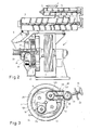
- a worm 22 is rotatably mounted and can be driven, for example, by a separate motor 23 - (FIG. 2) directly or, preferably, by means of an intermediate gear lying between it.
- the screw housing 21 has an opening in the area of the stripping knife 15, which, as shown in FIGS. 1 and 2, lies directly below the knife 15, so that the stripped pellets fall into the screw housing 21 and there with the help of the screw 22 against an inclined shaft 24 are carried on at the other end of the screw housing.
- the still warm and moist or relatively soft pellets fall via this inclined shaft 24 into the lower end of the inlet shaft 6, from where they, mixed with the new material supplied by the mixer 4 from above, are again fed to the die cover 8 for further pressing .
- the pellet press 1 processes the supplied material in two ways.
- the material converted into a soft, deformable state in the mixer is brought into a shape corresponding to the cross-sectional shape of the holes in the die 7; on the other hand, it cannot be missed that with the pressing of the rollers 9, 10 on the inner surface of the die 7 there is also a certain amount Crushing effect is connected.
- the fact that the material which has already been pelletized once again is fed to the perforated die 7 doubles the downsizing effect, whereby significantly higher densities of the end product can be achieved.
- the pellets produced in this way are on the one hand more resistant to abrasion or can also be used for the pressing of less suitable material for producing the pellets. This, in turn, is at least partly due to the fact that the material remains in the hot, moist state for a longer period of time, the individual parts are therefore better soaked, and are also exposed to the heat for longer, which additionally improves the sterilization effect.
- a screw 22 does not necessarily have to be used for the return arrangement, but rather a purely falling conveyance of the pelletized material could also take place if the housing tube 21 is arranged appropriately inclined.
- a conveying device e.g. to provide a screw, in particular a mixer screw.
- the upper guide vane 11 extends only over part of the axial length of the die cover 8 and is given due to the transverse position of the lower guide vane 12 (cf. FIG. 1 ) and the associated impossibility of access to the perforated die 7 from the material newly added from the filling shaft - first the fresh material, but the guide vane 12, which extends over the entire axial length, does the rest.
- FIGS. 3 and 4 is a modification of one, for example from US Pat. Nos. 3,045,280, 3,932,091 or 4 162 881 show known screw feeders for a punch die 7. All parts of the same function as in the previously described embodiment have the same reference numerals and parts of similar functions have the same reference numerals but with a hundreds number. It is assumed here that the perforated die 7 rotates clockwise in the same way as in the previous exemplary embodiment. The drive for this is not shown and can be designed according to the previous figures. According to the above-mentioned US patents, a feed screw 26 is supplied with the fresh material coming from the feed apparatus (see FIGS. 3, 4 in FIG. 2) via a feed shaft 106. As shown in FIG. 3, the screw 26 lies in front of the press roller 9 in relation to the direction of rotation of the die 7.
- a feed screw 126 is also arranged in front of the press roll 10, as it corresponds to the known embodiment. Deviating from this, however, the screw 126 does not receive the material to be fed to the roll 10 via the inlet shaft 106, but via a lateral channel 124 which, in contrast to the inclined shaft 24 in the exemplary embodiment according to FIGS. 1 and 2, is arranged essentially horizontally and therefore in inside a conveyor, preferably in the form of a screw 27, hides.
- the worm 27 is driven by a motor 123, which is only indicated in FIG. 4.
- the material stripped from the die 7 is fed to the channel 124 via a screw 122.
- this worm 122 is driven by means of a chain 28 from the die drive, although it is preferred in itself to provide a separate worm drive, which can then be pivoted easily with the front housing (see FIG. 20 in FIG. 1). It is only to be shown here that one is in no way restricted to this type of drive when implementing the invention.
- the worm 122 rotates in a worm housing 121 which in turn has an opening 29 at the end facing the die 7.
- a tab 30 of this_housing 121 is bent out of the cylinder plane and also serves as a doctor blade.
- the entire housing 121 can be adjusted toward or away from the punch die 7 with the aid of the handwheel 16 (FIG. 3). which is relatively easy to do in the case of the drive via the chain 28 or even with a separate drive.
- the opening 31 in the housing 120 receiving the screw housing 121 needs to be dimensioned somewhat larger in order to permit a transverse movement of the screw housing 121.
- the fresh material is first fed to the press roller 9 via the screw 26 and is thus pelletized for a first time, after which it is fed into the screw housing 121 through the tab 30.
- the pelletized material is then fed from the screw 122 to the transverse channel 124 with the screw 27, which again feeds the pelletized material via the feed screw 126 to the punch die 7, this time the press roller 10 comes into effect.
- the knife 14 therefore strips off the material which has now been pelletized for the second time.
- the pellet press 101 according to Rg. 5 has a stationary perforated die 107, whereas a ring gear 45 is driven in the counterclockwise direction and, on the one hand, the pressing rollers 109, 110 rolling on the inner surface of the die 107 and in FIG nter way carries spatially curved guide vanes 111, 112, but also at its edge two stripping blades 114, 115, which may be formed in a known manner from leaf spring material.
- the material stripped by the wipers 114, 115 falls on the right-hand side (with reference to FIG. 5) of the perforated die 107 into a funnel 46, on the bottom of which a return screw 222 is provided.
- This return screw 222 conveys the material collected by the hopper 46 to the outside in a manner not shown, or into a channel leading upwards into the feed chute, in which the material is carried upwards by any conveyor device.
- the material stripped off on the left-hand side of the punch die falls directly into the outlet 117, the ratio of the material pelletized to the hopper 46 to the pelletized material supplied to the outlet 117 possibly being adjustable by means of a flap 47.
- This flap 47 can be connected to a control loop, as will be discussed later with reference to FIG. 12, the flap 47 being adjusted as a function of a quality measurement of the pellet quality.
- an inner die 307 is in principle similarly equipped with press rollers 9 and 10 and guide vanes 11 and 12, as was shown with reference to FIGS. 1 to 4, but expediently feeding the material into the interior of the die die 307 via not shown, separate feed devices, for example corresponding to the feed screws 26, 126 of FIG. 3, are carried out.
- the guide vanes 11, 12 can then protrude further into the interior of the die 307 and only have a distribution function there.
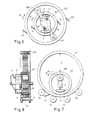
- the support plate 48 for the press rollers 9 and 10, as well as the guide vanes 11 and 12 can be extended via the perforated die 307 and carry further press rollers 209, 210 at their outer ends, which interact with an outer perforated die 207.
- Each of the two perforated dies 207, 307, which are expediently driven by a common drive, are assigned two stripping knives 14, 15 and 214, 215, respectively.
- the pelletized material stripped by the knives 14, 15 can thus fall directly onto the inner surface of the outer die 207 (simplified feed arrangement), from which it is carried and fed to the press rollers 209, 210.
- the material, which has already been pelletized, is pressed through these outer pressing rollers 209, 210 again, and if necessary, a third hole matrix in an analogous arrangement can also be provided outside the hole matrix 207. If necessary, appropriate spreading or spreading between the two matrices 207, 307.
- Distribution devices are provided to prevent material accumulation and to ensure an even distribution of material.
- press rolls may be provided within the inner die 407, but it may prove useful, at least at the point of contact P of the two hole dies zen 207, 407 opposite point to provide a press roll 309 so as to equalize or equalize the forces acting on the inner die 207.
- the material is fed via the feed chute 6 to the die cover 8, which rotates with the die shape 407, where it is distributed over the inner surface of the lid 8 under the action of centrifugal force, and is then stripped off by the guide vane 12.
- the guide vane 12 guides the material into the interior of the die 407, but, due to its position on the underside of the die 407, blocks the material flow when the die is at a standstill.
- the material introduced into the die 407 is finally pressed by the press roller 309 through the holes in the die 407, whereupon the pressed material, upon further rotation of the die 407, is pressed against the inner surface of the die 207, through the holes of which it is pressed and finally by the knife 14 is stripped.
- the outer die 207 is either carried along by the drive of the inner die 407 via a shaft 49 and therefore only needs to be supported, or is given its own drive via the support wheels 50, in which case a separate drive of the inner die 407 may be omitted.
- a corresponding pressing device for example on the inside of the die 407, can also be located in the region of the contact point P.
- one or two press rollers can be provided. However, an arrangement of the press rollers is preferred in which the axes of two such rollers lie on both sides of the axis of rotation of the inner die 407 approximately on a horizontal plane. Tests have shown that this arrangement is the cheapest in terms of force.
- the outer die 207 (if such is to be present) is expediently driven at its edge, as can be seen from FIG. 8.
- the drive can be in the form of a mere friction wheel drive, as is carried out in large tube mills, but toothed rings can also be provided.
- a friction wheel drive it may be expedient to arrange the surfaces of the die 207 opposite the drive wheels 50 on a different diameter than the outer surface carrying the perforation holes, in order to avoid contamination of the drive surface by the pelletized material.
- appropriate shields (sheets or the like) can also be provided. As a rule, however, it will be sufficient and most expedient to arrange the running surfaces of the outer die, on which the drive wheels 50 roll, on a smaller radius than the perforated outer surface.
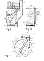
- a ring die 507 according to FIG. 11 is driven to rotate in a clockwise direction (arrow 25), the corresponding drive not being shown and being able to be designed analogously to the embodiment according to FIGS. 1 and 2.
- the pressing rollers 9, 10 are in turn rotatable, the axes 51 of which are held by a stationary plate 148.
- the plate 148 may additionally be supported in a known manner.
- Other parts, which are known but not shown, may be formed by corresponding guide blades or a doctor blade for the finished product corresponding to the doctor blade 14.
- the die surface F in the position of the stripper 315 according to FIG. 9 is divided into a strip 2F / 3 and a strip F / 3, in the position according to FIG. 10 in each case into a strip F / 2.
- the scraper 315 is provided with a pipe socket 52 (FIGS. 9, 11) which can be brought into any desired position on a funnel pipe 53 connected to the filling shaft 6 and can be clamped for example by means of a wing screw 54.
- the stripper 315 can also be brought into a rest position, in which it does not cover the surface F of the die 507. Since the stripper 315 is guided through a pipe socket 52, it is also easily adjustable in height.
- inclined shafts 224, 324 are provided, which feed the material stripped by the stripper 315 and conveyed into the funnel tube 53 to the press rollers 9, 10.
- the feed takes place in such a way that the material does not pass onto one of the wipers 315 swept over the flat strip of the die 507, so that the pelletized material M2 emerging from this strip was subjected to a double pelletization, the material MI only a single one. It may be desirable to produce a mixture of the two materials MI, M2, and this takes place when the scraper 315 is positioned as shown in FIG. 9. The material MI in the middle is then removed elsewhere by a scraper, not shown.
- the setting of the stripper 315 according to FIG. 10 should be selected.
- the material MI which was fed in via the feed chute 6 and pressed out by the press rolls on the surface strip adjacent to this chute 6, strikes the scraper 315, whereby due to the high peripheral speed of the die 507, a trajectory according to arrow 55 (FIG 10) results for the material MI.
- additional guide devices can also be provided.
- the material M1 intercepted in this way by the stripper 315 is now fed to the left strip (based on FIGS. 9 and 10) via the inclined shafts 224, 324, and is thus pelletized again with the help of the press rollers 9, 10.
- This double-pelletized material M2 is then stripped by the stripping knife 14 (not shown) (see the previous figures). If, on the other hand, only simple pelletized material is to be produced, the stripper 315 is either completely removed or brought into a position in which it is essentially parallel to the planes of the end faces of the die 507 or the die cover 8.
- the inclined shafts 224, 324 are expediently exchangeably fastened to the plate 148.
- the associated partition walls 56 in particular in the lower area of the die 507, are essentially disc-shaped in the embodiment shown (FIG. 11), but preferably extend over a relatively large area similar to the guide vane 12 (see FIG. 1). to prevent the material to be pelletized for the first time from reaching the surface strip for the material that has already been pelletized to be pressed for the second time.
- they can also be telescopically collapsible from individual gutter sections.
- the attachment to plate 148 (or another fixed attachment option) must also be adjustable.
- Combinations of radially and axially adjacent die surfaces corresponding to a combination of an embodiment according to FIGS. 6, 7 or 8 with an embodiment according to FIGS. 9 to 11 are also suitable for more than twice pressing. It is also conceivable to arrange matrices of different diameters axially next to one another (if this should be necessary for any reason) in the manner of FIGS. 9 to 11. Finally, it should also be pointed out that, when the wipers 315 are in the rest position, practically both surface strips (ie the total area F of the die 507) operate to a certain extent “in parallel operation”, and that such parallel operation is also possible in principle in the case of FIGS. 6 to 8 is only to be ensured that the outer die 207 also receives a corresponding material supply and the material stripped from the knives is removed separately.
- a pellet press 201 with a metering screw 3 and a mixer 4 is provided, which are arranged, for example, on a common shaft. Steam can be supplied via an inlet 5.
- the pelletized product reaches a transport line 57, which is the pellet of a qua Lticiansprüf Hughes 58 general type or a specially trained quality testing device 158 supplies.
- a switching device 59 is indicated schematically as a two-way valve, but in practice this valve 59 will be designed in the way that will be explained later with reference to FIG. 15.
- a cooling device 60 can be interposed within the line 57.
- the quality checking device 58 can be designed in one of the ways described in EP-OS 40 406 or according to the prior art.
- the pelletized material corresponding to a target standard will be produced at the outlet of the quality testing device 58 and will be fed from there to further use, whereas small parts, fragments or pelletized material which does not meet the quality requirements will be returned to the pellet press 201 via a return arrangement 424. specifically in this case it is preferably returned to the inlet funnel 2 for the purpose of further conditioning.
- a pneumatic quality checking device 158 is preferably used instead of any quality checking device 58.
- it can be one as described in EP-OS 95 168, which is essentially a pneumatic line with baffles provided therein.
- the baffles can simply be formed by elbows.
- a slow conveyor plug conveyor
- a secondary line 62 indicated by dashed lines, with valves 63 provided therein, via which Air is blown into the main line 64 carrying the product in order to divide the product into individual plugs and to assist in the transport of these plugs.
- a known feed device 65 is provided, which can be constructed in any known manner and does not necessarily have to be designed in the manner shown. Compressed air is fed to this feed device by a blower 66, whereby the material falling from the line 57 onto the base of the device is pressed into the mouth of the line 64 arranged in this area. At the same time, air is fed into the secondary line 62 from the top of the apparatus in a known manner.
- the naturally occurring pipe elbows or the friction on the pipe walls may contribute to the stress on the material, so that material of insufficient quality disintegrates, whereas material that meets the requirements reaches a cyclone separator 67 intact.
- the advantage of using a pneumatic quality testing device 158 is that it also achieves a certain cooling of the pelletized material, which makes quality testing easier. Therefore, it is preferred if any baffles, elbows, etc. are only provided from the second half of the length of the line 64 (with the exception of the initial pipe curvature in the feed apparatus 65).
- line 64 cannot be extended or shortened arbitrarily to adapt to different quality requirements, although this would also be conceivable if necessary.
- a simple possibility for adjusting the target quality is that the blower 66 is driven by a motor 68 of adjustable speed, an adjusting device 69 being provided for adjusting the speed of the motor 68 or for adjusting the desired target quality.
- the tested material passes into a separating device 70, which, as shown, is preferably formed by a sieve.
- the separating device 70 practically forms part of the entire testing device 158, wherein in the case of the quality testing device 58 the separating device can also be integrated and therefore does not then form a separate component.
- the screen 70 is relatively coarse-meshed, so that undamaged pellets remain on the surface and are repelled, whereas fragments and small parts fall through and are fed to the inlet funnel 2.
- the screen rejection reaches a cooler 160 if the pelletized material has not already cooled sufficiently in the pneumatic line 64 or the cyclone 67, as a result of which a separate cooler 160 can be omitted.
- a cooler 160 (known type)
- the line 71 leads the material of insufficient quality either directly back into the hopper 2, or via the feed ap ready 65, but the first variant is preferable.
- a switching valve 159 (corresponding to valve 59) can be provided.
- the return line 424 or the return arrangement 524 consisting of the line train 57, 62 to 65, 67 and 70 only returns the part that does not meet the quality requirements, the energy expenditure for that portion of the pelletized material that is already the Target quality corresponds and therefore no longer needs to be subjected to a pelletizing treatment.
- the construction essentially consists of two pellet presses 301, 401 (FIGS. 13, 16) which are independent of one another and can each be used for simple pelleting. These two pellet presses 301, 401 are now interconnected in a relatively space-saving manner side by side with mutually parallel axes of rotation, where the mixer 104 has the pellet press 301 placed que and connects to the metering device 203 of the pellet press 401. This metering device 203 receives the raw material in a manner known per se via a hopper 202.
- the conditioned raw material supplied to the pellet press 301 via the mixer 104 is compressed into pellets in the pellet press 301 for the first time (or already again if a pelletizing treatment has already been carried out); the pellets obtained at the outlet 217 can be fed to the feed chute 206 of the pellet press 401 with the aid of a feed arrangement 624.
- the feed arrangement 624 may in turn have a screw conveyor 622 which can be driven by a motor 623.
- the material which has already been pelletized in the pellet press 301 and fed to the pellet press 401 via the feed arrangement 624 is subjected to a pelletizing treatment in the latter press once again and leaves the pellet press 401 at its outlet 317.
- FIG. 14 This figure shows the feed apparatus 203 and the mixer 204 of the pellet press 401 underneath it.
- the drive motor 72 for the paddle screw of the metering apparatus 203 which can be seen in FIG. 16, can be operated in both directions of rotation by means of a reversing stage 73. In one direction of rotation, according to FIG. 14, the material is fed to the screw mixer 104 via the filling funnel 202 arranged approximately in the middle of the metering apparatus 203 in the direction of the arrow 74.
- the material then passes through the pellet presses 301, 401 one after the other.
- the direction of rotation of the motor 72 is reversed with the aid of the reversing stage 73 - (FIG. 16), and the metering device 203 conveys the material coming from the hopper 202 in the direction of the arrow 75 (Fig. 14) to mixer 204.
- the screw mixer 104 would thus remain without a feed, which is why a further hopper 102 is connected to a further feed apparatus 103 in this case. 16 feeds into the mixer 104.
- the reversing stage 73 is connected to a switching stage 76 via an output line, so that when switching over to series operation, i. when the direction of rotation of the motor 72 (FIG. 16) corresponds to the arrow 74 (FIG. 14), the power supply for the drive motor 172 of the feed apparatus 103 is automatically interrupted.
- the mixers 104, 204 are designed differently, but of course they can also be of the same design in any way per se.
- the feed instead of two feeders 103, 203, a single one can be provided, which, however, has the capacity to feed two pellet presses 301, 401 and whose output can be switched over in such a way that it can optionally only be used for series operation is connected to the mixer 104, for parallel operation, however, feeds both mixers 104, 204.
- the motor 72 can be a pole-changing motor which is switched to a lower speed during series operation, so that the oversized power of the common feeder is correspondingly reduced
- the corresponding drive motor for the feed apparatus is operated at the higher speed.
- the ratio of the quantities fed to the two pellet presses 301, 401 from the common feed apparatus in parallel operation is adjustable, but in particular is regulated as a function of the engine power (current consumption) of at least one of the presses 301, 401.
- the regulation can be carried out with the help of an extreme value selector analogous to the regulation described later.
- only one of the presses 301 or 401 can be operated, with the switch 76 remaining interrupted, for example.
- this can be implemented in two stages, as has become known, for example, from US Pat. No. 4,001,452, the upper stage of the feeder entering the mixer 104 facing side, this upper stage then conveys at the left end (based on FIG. 14) into a lower stage which is aligned in accordance with the mixer 204. In this way, the output and the input of the common feed apparatus can be on the same side and face the mixer 104. If the motor 172 is at a standstill, a silo closure may at the same time prevent further material supply to the hopper 102.
- the feed arrangement 624 can have a corresponding lockable flap following the exit 217, but the screw conveyor 622 can interfere and should therefore be shortened such that it does not reach the left end of the channel 624.
- the solution shown in FIGS. 13 and 15 is more favorable, in which an opening 417 can be closed by a flap 77.
- This flap 77 is pivotable about an axis 78 and can be brought into the dashed position shown in FIG. 15, in which it blocks the outlet opening 217 connected to the feed arrangement 624 and exposes the outlet opening 417.
- the pellet presses 301, 401 can be operated either in series or in parallel, so that no special constructions are required for the multiple pelletizing treatment and, moreover, the pellet presses 301, 401 can be better used for optional parallel operation.
- both pellet presses 301, 401 can easily be driven by a common motor 79.
- the control stages 73, 76 already described and the elements of the control circuit described below can then be accommodated in a control cabinet 80 arranged below the pellet press 301.
- the sensor may cause the pellet press 301 to switch off when the pellet press 301 runs out, if the pellet press 301 is already idling but the pellet press 401 still has to work. Even during operation, the two presses 301, 401 each have a different load due to control fluctuations and differently supplied quantities.
- a measurement arrangement for the respective output of the two pellet presses 301, 401 is therefore preferably provided, which in itself can be of any design. expediently, however, simply in a measuring device 82 or 182 for the strength of the current absorbed by the motors 179, 279. Such measuring arrangements are known per se and therefore do not need to be described in detail.
- the output signals of the two measuring devices 82, 182 are now fed to an extreme value selector 83, which only passes that signal to a control circuit 84 which corresponds to the greater power.
- the extreme value selector 83 will be a maximum value selector, but it would of course be conceivable to interpose an inverter stage between the measuring devices 82 or 182 and the extreme value selector 83, so that the extra value selector 83 acts as a minimum value selector would be operated.
- the structure of such an extreme value selector 83 is known per se and will be discussed later for better understanding with the aid of variants a) to e) of FIG. 17.
- the control circuit 84 receives a setpoint signal from a setpoint generator 85 and outputs a corresponding control signal to an output line 86 at its output.
- this output line 86 is shown as a bare line, but because of the different type of actuators to be actuated, it may also have different conversion stages for the signal.
- Such a conversion stage 87 is connected to the circuit of the feed motor 72 and is designed as a motor control stage of a known type.
- the feed is adapted to which of the two pellet presses 301, 401 has just reached its maximum output. Since different time constants are decisive for the adjustment of the power of the feed motor 72 to the maximum power of the pellet press 301 or 401, the controller 84 together with the selector 83 can have a different control behavior with different time constants, depending on whether the measurement signal passed by the selector 83 comes from the measuring device 82 or 182.
- a solenoid valve 88 in the steam supply line 5 can thus be set via the line 86, so that the viscosity, the temperature and / or the starch digestion of the material fed to the pellet presses 301, 401 is changed.
- a drive element 89 e.g. of a solenoid
- a flap 91 rotatable about a central axis 90 shown in FIG. 13 can be brought into the inclined position shown in FIG. 13, in which an opening of the feed arrangement 624 is released and part of the opening Outlet 217 coming material is discharged to the outside. This removed material can be fed to another pellet press, for example.
- control device 84 can actuate different actuators according to different laws, as is the case for the purpose of simple pelleting, for example from US Pat. Nos. 2,700,940 or 4,183,675, but also from PCT publications WO 81/02238 or WO 81/03076 has become known.
- the function of the selector or selection device 83 will now be explained on the basis of various design options according to FIG. 17.
- the variant a) shows an embodiment in which one of two measured values to be compared or selected is introduced via two input lines 33, 34.
- a comparator stage 35 which is formed by a differential amplifier with a high amplification factor, is connected to the input lines 33, 34.
- Two contacts 36, 37 are also connected to the input lines 33, 34.
- the switching tongue 38 of a changeover switch is normally on the contact 36, so that the signal from the input line 33 can reach an output line 40 directly via the contact 36.
- the measured value signal in line 34 falls only slightly by that of line 33, this small difference is already amplified to such an extent that a signal results at the output of comparator stage 35, by which a relay magnet 41 is excited and thus the Tongue 38 pulls against the contact 37.
- the parameter value thus comes from line 34 directly to output 40.
- the circuit has the function of a gate circuit which only allows an input signal to pass under predetermined circumstances.
- a switching stage 42 or 43 is connected on the one hand directly and on the other hand via an inversion element 44 at the output of the comparator stage 35.
- the comparator stage 35 is also formed here by a high-gain differential amplifier, at the output of the comparator stage 35, with a small positive difference, there is a signal which the switching stage 42 directly switches off in the sense of switching the input line 34 through gear 40 actuated.
- Variant d) shows that it is not absolutely necessary to compare two measured values with one another, but rather a threshold value switch 135 can be used to compare a measured value signal arriving via line 33 with a fixed value given by a resistor R5 (or by a voltage divider) , which is connected to the threshold switch 135 via an input line 134.
- the arrangement is such that a switch stage 142 normally connects line 134 to output line 40.
- a signal is produced at its output either when the threshold is exceeded or when it falls below a predetermined threshold.
- the threshold is selected and set so that it corresponds to an upper or lower threshold.
- the output signal at the output of the threshold switch 135 closes the switching stage 143 directly, whereas the switching stage 142 is opened via an inverter 40, so that instead of the signal from the line 134 the measurement signal from the line 33 now reaches the output line 40.
- the circuit is basically the same, but the diodes D1, D2, D3 are reversed, so that the process is reversed. Accordingly, the minimum voltage U1 flows through the output line 40, the diode D1 being open, the diodes D2, D3 lock.
- the resistor R6 can be adjusted in both variants if necessary. If it was said here that in the case of variant c) the maximum voltage U3, in the case of variant e) the voltage U1 flows via the output line 40, the voltage drop across the respective diode must of course also be taken into account.
- the circuits according to variants a), b) and d) are essentially lossless. It also goes without saying that, in the case of variants c) and e), that diode opens at which the corresponding extreme value is present, so that here the extreme value is selected from a plurality of input measured values using a relatively simple circuit.
- both presses 301, 401 have a single lifting device for lifting the die shapes of the two presses (or other heavy parts) in common.
- This can be done in such a way that in the arrangement according to 13 to 16 approximately in the middle between the presses 301, 401 - (based on Rg. 13), against the front with the feed shafts 6 to a mast with a swiveling boom on both sides, on which this is now optional to the press 301 or 401 swiveling hoist is attached.
- a rail runs across the two presses 301, 401 on which the hoist, e.g. a pulley can be moved to one or the other press in the manner of a trolley.
- a further advantageous modification in the case of FIGS. 13 to 16 may consist in that the portion of the metering screw 203 extending between the filling hopper 202 and the screw mixer 104 is omitted, the metering screw 203 in the parallel operation of the two presses 301, 401 only in one Direction in the mixer 204 promotes, however, is switched off in series operation.
- the interrupter stage 76 is provided in the circuit of the motor 72, while the reversing stage 73 can be omitted.
- the metering screw 103 feeds into the mixer 104 both in series and in parallel operation. The construction can thus be simplified in this way.
- switchover flap 77 can also be provided, for example in the case of an embodiment according to FIGS. 5, 6 or 9 to 11, in order to either operate in parallel or in series, or only to operate a die or die surface enable.
- Another possibility is to regulate the pressure of the rollers or the speed of the drive of the pressure pelletizer of the measuring device 82, 182, as has already been proposed for a pressure pelletizer.
Landscapes
- Engineering & Computer Science (AREA)
- Mechanical Engineering (AREA)
- Life Sciences & Earth Sciences (AREA)
- Chemical & Material Sciences (AREA)
- Polymers & Plastics (AREA)
- Food Science & Technology (AREA)
- Zoology (AREA)
- Processing And Handling Of Plastics And Other Materials For Molding In General (AREA)
- Feeding, Discharge, Calcimining, Fusing, And Gas-Generation Devices (AREA)
- Meat, Egg Or Seafood Products (AREA)
- Apparatuses For Bulk Treatment Of Fruits And Vegetables And Apparatuses For Preparing Feeds (AREA)
- Extrusion Moulding Of Plastics Or The Like (AREA)
- Disintegrating Or Milling (AREA)
- Crystals, And After-Treatments Of Crystals (AREA)
Priority Applications (1)
| Application Number | Priority Date | Filing Date | Title |
|---|---|---|---|
| AT86106016T ATE54606T1 (de) | 1985-05-09 | 1986-05-02 | Verfahren zum erzeugen eines pelletierten futtermittels, und vorrichtung zur durchfuehrung des verfahrens. |
Applications Claiming Priority (2)
| Application Number | Priority Date | Filing Date | Title |
|---|---|---|---|
| CH196285 | 1985-05-09 | ||
| CH1962/85 | 1985-05-09 |
Publications (3)
| Publication Number | Publication Date |
|---|---|
| EP0201052A2 true EP0201052A2 (fr) | 1986-11-12 |
| EP0201052A3 EP0201052A3 (en) | 1987-11-19 |
| EP0201052B1 EP0201052B1 (fr) | 1990-07-18 |
Family
ID=4222672
Family Applications (1)
| Application Number | Title | Priority Date | Filing Date |
|---|---|---|---|
| EP86106016A Expired - Lifetime EP0201052B1 (fr) | 1985-05-09 | 1986-05-02 | Procédé pour la production d'un fourrage pelletisé et appareil pour la réalisation du procédé |
Country Status (4)
| Country | Link |
|---|---|
| US (1) | US4817517A (fr) |
| EP (1) | EP0201052B1 (fr) |
| AT (1) | ATE54606T1 (fr) |
| DE (1) | DE3672673D1 (fr) |
Cited By (4)
| Publication number | Priority date | Publication date | Assignee | Title |
|---|---|---|---|---|
| CN104857893A (zh) * | 2015-04-24 | 2015-08-26 | 南京理工大学 | 环模制粒机等厚度铺料器 |
| CN110239137A (zh) * | 2019-05-24 | 2019-09-17 | 合肥鸿强冶金科技有限公司 | 一种高效率秸秆压块结构 |
| EP4180218A1 (fr) | 2021-11-12 | 2023-05-17 | Maschinenfabrik Bermatingen GmbH & Co. KG | Procédé et dispositif de fabrication de pellets |
| EP4434737A1 (fr) * | 2023-03-24 | 2024-09-25 | Salmatec GmbH | Dispositif de coupe à longueur pour une presse à granulés et presse à granulés |
Families Citing this family (17)
| Publication number | Priority date | Publication date | Assignee | Title |
|---|---|---|---|---|
| JPH0628244Y2 (ja) * | 1990-02-09 | 1994-08-03 | 駿河精機株式会社 | 発泡プラスチックの減容機 |
| US5263817A (en) * | 1991-06-03 | 1993-11-23 | California Pellet Mill Company | Apparatus for pelletizing coarsely ground particulate feed material |
| US5242292A (en) * | 1991-09-30 | 1993-09-07 | Wenger Manufacturing, Inc. | Extruder apparatus for producing sterile pelleted feed product |
| AU694490B2 (en) * | 1994-03-09 | 1998-07-23 | Wm. Wrigley Jr. Company | Method and apparatus for forming miniature size confectionery products |
| US6099288A (en) * | 1997-03-20 | 2000-08-08 | Mp6, L.L.C. | Pellet forming extrusion apparatus |
| WO2002096549A1 (fr) * | 2001-05-29 | 2002-12-05 | Spheriform Pty Ltd | Agglomeration de particules fines |
| ITFI20010201A1 (it) * | 2001-10-26 | 2003-04-26 | Ecotre System S R L | Metodo ed impianto per la produzione di pellets |
| ITRM20020145A1 (it) * | 2002-03-15 | 2003-09-15 | Fulvio Soldaini | Trafila perfezionata per macchine pellettizzatrici, macchina pellettizzatrice che comprende tale trafila perfezionata e metodo per la produz |
| US7875088B2 (en) * | 2006-02-03 | 2011-01-25 | EaglePicher Technologies | Automated tracking and storage system for use with an automated thermal battery manufacturing system |
| US7871447B2 (en) * | 2006-02-03 | 2011-01-18 | EaglePicher Technologies | System and method for manufacturing a thermal battery |
| US8052764B2 (en) * | 2006-02-03 | 2011-11-08 | Eaglepicher Technologies, Llc | System and method for manufacturing a thermal battery |
| WO2011101432A2 (fr) * | 2010-02-18 | 2011-08-25 | Bühler AG | Presse à boulettes |
| WO2014125111A1 (fr) | 2013-02-15 | 2014-08-21 | Bühler AG | Procédé et dispositif de bouletage de produit en vrac contenant du gluten |
| EP2857165B1 (fr) * | 2013-10-01 | 2019-03-13 | SABIC Global Technologies B.V. | Dispositif et procédé de formation des pastilles de mélange-maître pour des compositions thermoplastiques |
| WO2015087299A1 (fr) * | 2013-12-12 | 2015-06-18 | Vianello Dri Tommaso | Installation et procédé pour la fabrication de granulés d'alimentation à fibres longues destinés à un usage zootechnique |
| ITVI20130294A1 (it) * | 2013-12-12 | 2015-06-13 | Riccardo Bisazza | Impianto per la produzione di compresse alimentari a fibra lunga per uso zootecnico |
| ITUA20164301A1 (it) * | 2016-05-24 | 2017-11-24 | Maria Giovanna Gamberini | Termocompattatore |
Family Cites Families (34)
| Publication number | Priority date | Publication date | Assignee | Title |
|---|---|---|---|---|
| GB190748A (en) * | 1921-08-02 | 1923-01-02 | Albert William Sizer | An improved machine for compressing or moulding plastic substances |
| US1877266A (en) * | 1928-06-02 | 1932-09-13 | Chapin George Maxson | Apparatus for the manufacture of feed for chickens and other animals |
| US2240660A (en) * | 1940-02-26 | 1941-05-06 | Edgar T Meakin | Extrusion mill |
| US2700940A (en) * | 1948-04-02 | 1955-02-01 | Clyde V Johnson | Apparatus for preparing moldable materials and producing pellets |
| US2764952A (en) * | 1948-09-07 | 1956-10-02 | Edgar N Meakin | Kibbling apparatus |
| US2798444A (en) * | 1952-11-29 | 1957-07-09 | Edgar N Meakin | Feed mechanism for extrusion mills |
| US2739895A (en) * | 1953-04-06 | 1956-03-27 | Nat Alfalfa Dehydrating And Mi | Method of making granular, dehydrated products |
| US2908038A (en) * | 1957-05-06 | 1959-10-13 | Edgar N Meakin | Extrusion mill feed assembly |
| US3045280A (en) * | 1959-07-10 | 1962-07-24 | Mahoney Thomas P | Pellet mill and feeder therefor |
| NL267832A (fr) * | 1960-12-27 | |||
| US3191227A (en) * | 1961-09-01 | 1965-06-29 | California Pellet Mill Co | Extrusion mill with vented feeder |
| US3181482A (en) * | 1962-01-18 | 1965-05-04 | Midwest Feed & Peileting Co In | Portable pellet mill apparatus |
| US3288051A (en) * | 1963-05-27 | 1966-11-29 | Dodgen Ind Inc | Apparatus for producing pellets for livestock feed |
| NL6412189A (fr) * | 1963-12-17 | 1965-06-18 | ||
| US3307501A (en) * | 1965-07-13 | 1967-03-07 | Wenger Mfg | Pellet mill |
| US3382818A (en) * | 1966-12-05 | 1968-05-14 | Landers Machine Company | Pellet mill feed receivers |
| US3581678A (en) * | 1969-03-12 | 1971-06-01 | Charles R Landers | Pellet mill with bearing and wear translative element |
| US3538546A (en) * | 1969-09-25 | 1970-11-10 | California Pellet Mill Co | Adjustable feed deflector |
| DE2129532A1 (de) * | 1971-06-15 | 1972-12-21 | Hamburger Maschb Jost Hinrich | Futtermittelpresse |
| NL7112111A (fr) * | 1971-09-03 | 1973-03-06 | ||
| US3981664A (en) * | 1974-10-25 | 1976-09-21 | Sprout, Waldron & Company, Inc. | Main shaft support for pellet mills |
| US3932091A (en) * | 1975-01-28 | 1976-01-13 | Johannes Albertus Vink | Pellet mill with separate fee means for each die roller |
| US4001452A (en) * | 1975-09-10 | 1977-01-04 | Central Soya Company, Inc. | Method of preparing animal food pellets |
| US4162881A (en) * | 1978-05-24 | 1979-07-31 | Morse George W | Pellet mill with improved feed system |
| US4183675A (en) * | 1978-10-20 | 1980-01-15 | Feed Pelleting, Inc. | Energy conserving method and apparatus for pelleting particulate animal feed |
| DK48080A (da) * | 1980-02-05 | 1981-08-06 | Soee Pedersen A | Automatisk reguleringssystem til pillepresse for produktion af piller |
| US4340937A (en) * | 1980-04-14 | 1982-07-20 | Beta Corporation Of St. Louis | Automatic control for a pellet producing apparatus |
| DK161438C (da) * | 1980-05-19 | 1993-09-27 | Buehler Ag Geb | Fremgangsmaade til styring af et foderterningpresseanlaeg, terningpresseanlaeg til udoevelse af denne fremgangsmaade, fremgangsmaade ved terningkvalitetsmaaling samt et apparat til udoevelse af denne fremgangsmaade |
| NL8005517A (nl) * | 1980-10-06 | 1982-03-01 | Wessanen Mengvoeders Bv | Veevoeder, werkwijze voor het persen van veevoederkorrels, alsmede inrichting voor het uitvoeren van deze werkwijze. |
| EP0095168B1 (fr) * | 1981-05-14 | 1987-10-28 | Bühler AG | Procédé pour mesurer la qualité de briquette et un dispositif pour mesurer la qualité de briquette |
| GB2105969A (en) * | 1981-09-19 | 1983-04-07 | Simon Barron Ltd | Production of animal feed by a double pelleting process |
| NL8201928A (nl) * | 1981-10-30 | 1983-05-16 | Chemische Ind En Handelmaatsch | Werkwijze voor het bereiden van een korrelvormig mengsel van toevoegsels voor de kunststofindustie door dergelijke toevoegsels te mengen en vervolgens tot een korrelvorm te verwerken. |
| DE3342660A1 (de) * | 1983-11-25 | 1985-06-05 | Howaldtswerke-Deutsche Werft Ag Hamburg Und Kiel, 2300 Kiel | Zweistufige pelletisiervorrichtung |
| US4711622A (en) * | 1984-07-04 | 1987-12-08 | Gebruder Buhler Ag | Pellet mill |
-
1986
- 1986-05-02 EP EP86106016A patent/EP0201052B1/fr not_active Expired - Lifetime
- 1986-05-02 DE DE8686106016T patent/DE3672673D1/de not_active Expired - Lifetime
- 1986-05-02 AT AT86106016T patent/ATE54606T1/de not_active IP Right Cessation
-
1988
- 1988-04-20 US US07/186,702 patent/US4817517A/en not_active Expired - Fee Related
Cited By (6)
| Publication number | Priority date | Publication date | Assignee | Title |
|---|---|---|---|---|
| CN104857893A (zh) * | 2015-04-24 | 2015-08-26 | 南京理工大学 | 环模制粒机等厚度铺料器 |
| CN104857893B (zh) * | 2015-04-24 | 2017-03-01 | 南京理工大学 | 环模制粒机等厚度辅料器 |
| CN110239137A (zh) * | 2019-05-24 | 2019-09-17 | 合肥鸿强冶金科技有限公司 | 一种高效率秸秆压块结构 |
| EP4180218A1 (fr) | 2021-11-12 | 2023-05-17 | Maschinenfabrik Bermatingen GmbH & Co. KG | Procédé et dispositif de fabrication de pellets |
| EP4434737A1 (fr) * | 2023-03-24 | 2024-09-25 | Salmatec GmbH | Dispositif de coupe à longueur pour une presse à granulés et presse à granulés |
| DE102023107468A1 (de) * | 2023-03-24 | 2024-09-26 | Salmatec Gmbh | Ablänganordnung für eine Pelletpresse und Pelletpresse |
Also Published As
| Publication number | Publication date |
|---|---|
| DE3672673D1 (de) | 1990-08-23 |
| EP0201052A3 (en) | 1987-11-19 |
| EP0201052B1 (fr) | 1990-07-18 |
| US4817517A (en) | 1989-04-04 |
| ATE54606T1 (de) | 1990-08-15 |
Similar Documents
| Publication | Publication Date | Title |
|---|---|---|
| EP0201052B1 (fr) | Procédé pour la production d'un fourrage pelletisé et appareil pour la réalisation du procédé | |
| EP0225351B1 (fr) | Appareil de sechage de boues de curage | |
| DE2600648C2 (de) | Pelletpresse | |
| DE1808969A1 (de) | Mischmaschine | |
| EP0091982A2 (fr) | Procédé et dispositif pour la séparation des bourres de cellulose et de leurs enveloppes dans les articles hygiéniques en cellulose | |
| EP2065174A2 (fr) | Dispositif de remplissage pour une presse à comprimés rotative | |
| WO2018153392A1 (fr) | Dispositif de conchage et procédé pour le conchage d'une masse de produit | |
| DE3015250C2 (de) | Verfahren und Einrichtung zur Aufbereitung von Mineralfaserschrott unterschiedlicher Beschaffenheit, insbesondere hinsichtlich seiner organischen Bestandteile | |
| DD291001A5 (de) | Verfahren und vorrichtung zur aufarbeitung von restteig zu neuteig | |
| DE3038794C2 (de) | Rührwerksmühle | |
| BE1021676B1 (nl) | Baustein-fertigungsanlage mit rührmitteln, die sich in bewegungsrichtung eines ladetroges ertreckende rotationsachsen aufweisen | |
| DE566820C (de) | Aus zwei hintereinandergeschalteten Pressvorrichtungen bestehende OElsaatenpresse | |
| EP2560761B2 (fr) | Dispositif d'alimentation pour une presse à rouleaux à haute pression | |
| DE2111380B2 (de) | Vorrichtung zum pilieren von seifen oder aehnlichen, pastenartigen massen | |
| DE2638687C2 (de) | Verfahren und Vorrichtung zum Herstellen einer gleichmäßigen Schicht von losen Fasern oder Partikeln auf einer bewegten porösen Trägerbahn | |
| EP3985151B1 (fr) | Machine pour la préparation à la filature | |
| DE2559160C2 (fr) | ||
| DE7631186U1 (de) | Scheidepresse | |
| DE8804662U1 (de) | Hammermühle | |
| DE2704219C3 (de) | Verfahren und Vorrichtung zum Zerkleinern und Trocken-Defibrieren von Zellulosepulpe zwecks Herstellung einer Matte von Fasermaterial, die in Absorptionskörper für Windeln o.dgl. zerteilbar ist | |
| EP0913189A2 (fr) | Mélangeur-broyeur et méthode d'utilisation de ce dispositif pour des matériaux déchets, particulièrement pour des matériaux déchets biodégradables | |
| DE947060C (de) | Einrichtung und Verfahren zur Regelung der Diffusion von insbesondere Zuckerruebenschnitzeln | |
| AT346680B (de) | Vorrichtung zur behandlung von koernigem gut | |
| DE236635C (fr) | ||
| AT521707B1 (de) | Vorrichtung zum Herstellen von Pellets |
Legal Events
| Date | Code | Title | Description |
|---|---|---|---|
| PUAI | Public reference made under article 153(3) epc to a published international application that has entered the european phase |
Free format text: ORIGINAL CODE: 0009012 |
|
| AK | Designated contracting states |
Kind code of ref document: A2 Designated state(s): AT BE CH DE FR GB IT LI NL SE |
|
| PUAB | Information related to the publication of an a document modified or deleted |
Free format text: ORIGINAL CODE: 0009199EPPU |
|
| RA1 | Application published (corrected) |
Date of ref document: 19861217 Kind code of ref document: A2 |
|
| PUAL | Search report despatched |
Free format text: ORIGINAL CODE: 0009013 |
|
| RHK1 | Main classification (correction) |
Ipc: B30B 11/20 |
|
| AK | Designated contracting states |
Kind code of ref document: A3 Designated state(s): AT BE CH DE FR GB IT LI NL SE |
|
| 17P | Request for examination filed |
Effective date: 19871005 |
|
| 17Q | First examination report despatched |
Effective date: 19890215 |
|
| RAP1 | Party data changed (applicant data changed or rights of an application transferred) |
Owner name: BUEHLER AG |
|
| GRAA | (expected) grant |
Free format text: ORIGINAL CODE: 0009210 |
|
| ITF | It: translation for a ep patent filed | ||
| AK | Designated contracting states |
Kind code of ref document: B1 Designated state(s): AT BE CH DE FR GB IT LI NL SE |
|
| REF | Corresponds to: |
Ref document number: 54606 Country of ref document: AT Date of ref document: 19900815 Kind code of ref document: T |
|
| REF | Corresponds to: |
Ref document number: 3672673 Country of ref document: DE Date of ref document: 19900823 |
|
| GBT | Gb: translation of ep patent filed (gb section 77(6)(a)/1977) | ||
| ET | Fr: translation filed | ||
| PLBE | No opposition filed within time limit |
Free format text: ORIGINAL CODE: 0009261 |
|
| STAA | Information on the status of an ep patent application or granted ep patent |
Free format text: STATUS: NO OPPOSITION FILED WITHIN TIME LIMIT |
|
| ITTA | It: last paid annual fee | ||
| 26N | No opposition filed | ||
| PGFP | Annual fee paid to national office [announced via postgrant information from national office to epo] |
Ref country code: SE Payment date: 19940324 Year of fee payment: 9 |
|
| PGFP | Annual fee paid to national office [announced via postgrant information from national office to epo] |
Ref country code: FR Payment date: 19940330 Year of fee payment: 9 |
|
| PGFP | Annual fee paid to national office [announced via postgrant information from national office to epo] |
Ref country code: BE Payment date: 19940511 Year of fee payment: 9 |
|
| PGFP | Annual fee paid to national office [announced via postgrant information from national office to epo] |
Ref country code: AT Payment date: 19940526 Year of fee payment: 9 |
|
| EAL | Se: european patent in force in sweden |
Ref document number: 86106016.8 |
|
| PGFP | Annual fee paid to national office [announced via postgrant information from national office to epo] |
Ref country code: CH Payment date: 19950324 Year of fee payment: 10 |
|
| PGFP | Annual fee paid to national office [announced via postgrant information from national office to epo] |
Ref country code: GB Payment date: 19950419 Year of fee payment: 10 |
|
| PG25 | Lapsed in a contracting state [announced via postgrant information from national office to epo] |
Ref country code: AT Effective date: 19950502 |
|
| PG25 | Lapsed in a contracting state [announced via postgrant information from national office to epo] |
Ref country code: SE Effective date: 19950503 |
|
| PGFP | Annual fee paid to national office [announced via postgrant information from national office to epo] |
Ref country code: DE Payment date: 19950527 Year of fee payment: 10 |
|
| PG25 | Lapsed in a contracting state [announced via postgrant information from national office to epo] |
Ref country code: BE Effective date: 19950531 |
|
| PGFP | Annual fee paid to national office [announced via postgrant information from national office to epo] |
Ref country code: NL Payment date: 19950531 Year of fee payment: 10 |
|
| BERE | Be: lapsed |
Owner name: GEBRUEDER BUEHLER AG MASCHINENFABRIK Effective date: 19950531 |
|
| EUG | Se: european patent has lapsed |
Ref document number: 86106016.8 |
|
| PG25 | Lapsed in a contracting state [announced via postgrant information from national office to epo] |
Ref country code: FR Effective date: 19960229 |
|
| REG | Reference to a national code |
Ref country code: FR Ref legal event code: ST |
|
| REG | Reference to a national code |
Ref country code: FR Ref legal event code: ST |
|
| PG25 | Lapsed in a contracting state [announced via postgrant information from national office to epo] |
Ref country code: GB Effective date: 19960502 |
|
| PG25 | Lapsed in a contracting state [announced via postgrant information from national office to epo] |
Ref country code: LI Effective date: 19960531 Ref country code: CH Effective date: 19960531 |
|
| PG25 | Lapsed in a contracting state [announced via postgrant information from national office to epo] |
Ref country code: NL Effective date: 19961201 |
|
| GBPC | Gb: european patent ceased through non-payment of renewal fee |
Effective date: 19960502 |
|
| REG | Reference to a national code |
Ref country code: CH Ref legal event code: PL |
|
| PG25 | Lapsed in a contracting state [announced via postgrant information from national office to epo] |
Ref country code: DE Effective date: 19970201 |
|
| NLV4 | Nl: lapsed or anulled due to non-payment of the annual fee |
Effective date: 19961201 |
|
| PG25 | Lapsed in a contracting state [announced via postgrant information from national office to epo] |
Ref country code: IT Free format text: LAPSE BECAUSE OF NON-PAYMENT OF DUE FEES;WARNING: LAPSES OF ITALIAN PATENTS WITH EFFECTIVE DATE BEFORE 2007 MAY HAVE OCCURRED AT ANY TIME BEFORE 2007. THE CORRECT EFFECTIVE DATE MAY BE DIFFERENT FROM THE ONE RECORDED. Effective date: 20050502 |