EP0201082A2 - Mounting structure for a vehicle suspension - Google Patents
Mounting structure for a vehicle suspension Download PDFInfo
- Publication number
- EP0201082A2 EP0201082A2 EP86106197A EP86106197A EP0201082A2 EP 0201082 A2 EP0201082 A2 EP 0201082A2 EP 86106197 A EP86106197 A EP 86106197A EP 86106197 A EP86106197 A EP 86106197A EP 0201082 A2 EP0201082 A2 EP 0201082A2
- Authority
- EP
- European Patent Office
- Prior art keywords
- bracket
- shock absorber
- upper arm
- suspension
- arm
- Prior art date
- Legal status (The legal status is an assumption and is not a legal conclusion. Google has not performed a legal analysis and makes no representation as to the accuracy of the status listed.)
- Granted
Links
Images

Classifications
-
- B—PERFORMING OPERATIONS; TRANSPORTING
- B60—VEHICLES IN GENERAL
- B60G—VEHICLE SUSPENSION ARRANGEMENTS
- B60G15/00—Resilient suspensions characterised by arrangement, location or type of combined spring and vibration damper, e.g. telescopic type
- B60G15/02—Resilient suspensions characterised by arrangement, location or type of combined spring and vibration damper, e.g. telescopic type having mechanical spring
- B60G15/06—Resilient suspensions characterised by arrangement, location or type of combined spring and vibration damper, e.g. telescopic type having mechanical spring and fluid damper
- B60G15/067—Resilient suspensions characterised by arrangement, location or type of combined spring and vibration damper, e.g. telescopic type having mechanical spring and fluid damper characterised by the mounting on the vehicle body or chassis of the spring and damper unit
- B60G15/068—Resilient suspensions characterised by arrangement, location or type of combined spring and vibration damper, e.g. telescopic type having mechanical spring and fluid damper characterised by the mounting on the vehicle body or chassis of the spring and damper unit specially adapted for MacPherson strut-type suspension
-
- B—PERFORMING OPERATIONS; TRANSPORTING
- B60—VEHICLES IN GENERAL
- B60G—VEHICLE SUSPENSION ARRANGEMENTS
- B60G7/00—Pivoted suspension arms; Accessories thereof
- B60G7/02—Attaching arms to sprung part of vehicle
Definitions
- This invention relates to a mounting structure for a suspension and, more particularly, to a mounting structure for joining an upper portion of a double wishbone type suspension of an automobile with a car body.
- a double wishbone type suspension is usually provided with an upper arm having a pair of arm portions extending inward from a joining portion having a steering knuckle and being mutually spaced in front and to the rear of each other in the longitudinal direction of the vehicle, as well as a shock absorber and a coil spring surrounding the shock absorber.
- These parts are mounted on a car body such that the shock absorber and the coil spring are disposed in the space between the arm portions (for example, as shown in Japanese Utility Model Public Disclosure (KOKAI) No. 182407/84).
- the arm portions of the upper arm are first joined with the car body and then the shock absorber and the coil spring are joined with the car body, or the order of mounting these parts is reversed.
- two bolts each of which has a head with a hole, are extended upwardly through and fixed to a rectangular section attaching portion of a car body.
- a third bolt is inserted into the holes of the two bolts, a nut is screwed onto the bolt, and an upper arm is connected with the third bolt, and thus to the car body.
- the space provided for mounting an upper arm is narrow and is surrounded by a fender, hood, dash panel or the like and further the upper arm must be assembled with high torque so as to be able to withstand the forces applied during travel. As a result, operations necessary for mounting the parts are complicated and the automation of these operations is made difficult.
- An object of the present invention is to eliminate the assembly restrictions arising in joining a shock absorber after or before the joining of an upper arm.
- a structure for mounting a suspension on a vehicle body in which a shock absorber and an upper arm connected to a steering knuckle and extending inward is supported by a bracket pivotally connected to the upper arm and connected to a piston rod of the shock absorber, wherein said upper arm and said shock absorber are mounted on the car body via the bracket.
- the upper arm has a pair of arm portions extending inward from a joining portion which is connected to the steering knuckle and mutually spaced to the front and rear in the vehicle longitudinal direction.
- a coil spring is provided to surround the shock absorber. The shock absorber and the coil spring are disposed in a space between the arm portions and the bracket receives an upper end of the coil spring.
- shock absorber and coil spring are mounted on the car body, a lower end of the shock absorber and the steering knuckle can be joined with a lower arm, and the lower arm can be pivotally joined with a subframe.
- a so-called subassembly can thus be constituted in order to permit wheel alignment to be coordinated, so that productivity is improved.
- a mounting structure 10 for mounting the upper arm 12, shock absorber 14 and coil spring 16 on a car body 18 (Figure 2) includes a bracket 20.
- the upper arm 12 is integrally formed with joining portion 13a and a pair of arm portions 13b, 13c extending inward from the joining portion 13a and spaced in front and to the rear of one another in the longitudinal direction of the vehicle.
- a steering knuckle 22 is joined with the joining portion 13a through a ball joint 24.
- the pair of arm portions 13b, 13c are respectively provided at their free ends with eyes 26 ( Figure 2).
- the shock absorber 14 is a twin tube type or monotube type which is well known, per se. As shown in Figure 3, the shock absorber 14 has a lower end pivotally joined with a lower arm 28 and an upper end joined with the bracket 20 by a structure which will be later described.
- the lower arm 28 supports the steering knuckle 22 at an outer end thereof via a ball joint (not shown).
- the coil spring 16 is disposed to surround the shock absorber 14 and has a lower end mounted on a spring sheet 30 welded to a cylinder of the shock absorber 14.
- the shock absorber 14 and the coil spring 16 are disposed in a space 32 between the arm portions 13b, 13c of the upper arm 12.
- the bracket 20 has lateral first and second mounting portions 21a, 21b and a central third mounting portion 21c. These mounting portions are press formed of sheet material.
- the third mounting portion 21c is positioned above the first and second portions 21a, 21b and is formed in a ring-shape.
- the bracket 20 has a pair of mounting members 34 fixed respectively to the first and second mounting portions 21a, 21b.
- Each member 34 has a U-shaped configuration as viewed from the front side.
- Bolts 36 two of which extend vertically through the mounting member 34, are press fitted in the first and second mounting portions 21a, 21b respectively via serrations thereon or are welded thereto.
- An additional bolt 36 is centrally mounted on the bracket.
- the bolts 36 connect the bracket 20 with the car body 18 and two of a plurality of bolts preferably also fix the-mounting members 34.
- Rubber bushings (not shown) are attached within the respective eyes 26 in arm portions 13b and 13c of the upper arm 12. These eyes are positioned within the mounting members 34, a bolt 38 is inserted through each of the mounting members and bushing, and a nut 40 is threaded onto each bolt, so that the respective arm portions 21a, 21b of the upper arm 12 are pivotally joined with the bracket 20.
- a pair of support plates 44 are bonded to the central portion of a rubber bushing 42 and a support plate 46 is bonded to a peripheral edge of the bushing 42.
- An end of the piston rod 15 extends through the support plates 44 and a nut 48 is threaded onto said end.
- a plurality of bolts 50 (two bolts are shown in Figure 1) are press fitted into the support plate 46 via serrations thereon and extend through the third mounting portions 21c of the bracket 20 and nuts 52 are threaded respectively onto the bolts 50 to join the piston rod 15 with the bracket 20.
- An upper end of the coil spring 16 bears against the bushing 42.
- the upper arm 12, shock absorber 14 and coil spring 16 are connected to the bracket 20 and an inner end of the lower arm 28 is pivotally joined with a subframe 54 to constitute a subassembly 56.
- the wheel alignment can be coordinated with this subassembly 56 before incorporating the subassembly into the car body.
- the bolts 36 of the bracket 20 extend through the car body 18 and nuts 58 are respectively screwed onto the bolts 36 to join the bracket 20 thereto, thereby joining the subassembly 56, the upper arm 12, shock absorber 14 and coil spring 16 with the car body.
- a bracket 60 shown in the second embodiment of Figures 4 and 5 has first and second lateral mounting portions 61a, 61b on both sides thereof and a third central mounting portion 61c. These mounting portions are press formed from a sheet material. Ribs 61d extend from a step portion joining the third mounting portion with the first and second mounting portions. The third mounting portion 61c is formed in a ring-shape having a central hole 62 and three holes 64 though each of which a bolt for connecting the bracket 60 with the shock absorber extends.
- a support (not shown) similar to that of the first embodiment and including a rubber bushing is disposed between the bracket 60 and the shock absorber.
- the bracket 60 has a pair of mounting members 66, each having first and second portions 67a, 67b formed of a sheet material.
- the first portion 67a is bent in U-shape and formed flat at its top.
- the second portion 617b is a flat U-shape sheet and is welded to the first portion 67a.
- Two bolts 68 extend through the first portion 67a of each of the mounting members 66 and are press fitted in the respective mounting portion of the bracket 60 facing the flat top of the first portion 67a.
- the first portion 67a of the mounting member 66 has holes 70 on its sides.
- the eye 26 of the arm portion of the upper arm 12 is disposed in a space defined by the parallel legs of the U-shaped first portion 67a.
- a bolt extends through the eye 26 and the holes 70 and a nut is screwed onto the bolt.
- the upper arm 12 is connected to the bracket 60.
- the bracket 60 is mounted on the car body through the four bolts 68.
- the upper arm 12 has two arm portions 13b, 13c spaced in front and to the rear of each other.
- a so-called I type arm like the lower arm 28 in Figure 3 may be used as an upper arm.
- the bracket 20 has only one mounting portion for the upper arm.
- the coil spring 16 may be disposed independently of the shock absorber 14. In this case, the upper end of the coil spring 16 is pressed not on the bracket but on the car body.
Landscapes
- Engineering & Computer Science (AREA)
- Mechanical Engineering (AREA)
- Vehicle Body Suspensions (AREA)
Abstract
Description
- This invention relates to a mounting structure for a suspension and, more particularly, to a mounting structure for joining an upper portion of a double wishbone type suspension of an automobile with a car body.
- A double wishbone type suspension is usually provided with an upper arm having a pair of arm portions extending inward from a joining portion having a steering knuckle and being mutually spaced in front and to the rear of each other in the longitudinal direction of the vehicle, as well as a shock absorber and a coil spring surrounding the shock absorber. These parts are mounted on a car body such that the shock absorber and the coil spring are disposed in the space between the arm portions (for example, as shown in Japanese Utility Model Public Disclosure (KOKAI) No. 182407/84).
- When such suspension components are to be mounted on the car body, the arm portions of the upper arm are first joined with the car body and then the shock absorber and the coil spring are joined with the car body, or the order of mounting these parts is reversed.
- In a mounting structure disclosed in Japanese Patent Public Disclosure No. 96007/84, two bolts, each of which has a head with a hole, are extended upwardly through and fixed to a rectangular section attaching portion of a car body. A third bolt is inserted into the holes of the two bolts, a nut is screwed onto the bolt, and an upper arm is connected with the third bolt, and thus to the car body.
- The space provided for mounting an upper arm is narrow and is surrounded by a fender, hood, dash panel or the like and further the upper arm must be assembled with high torque so as to be able to withstand the forces applied during travel. As a result, operations necessary for mounting the parts are complicated and the automation of these operations is made difficult.
- Also, when the joining of the upper arm precedes the joining of the shock absorber and coil spring or vice versa, the space available for the steps of mounting the following parts may often be restricted, which hinders improvements in productivity.
- An object of the present invention is to eliminate the assembly restrictions arising in joining a shock absorber after or before the joining of an upper arm.
- According to the present invention there is provided a structure for mounting a suspension on a vehicle body in which a shock absorber and an upper arm connected to a steering knuckle and extending inward is supported by a bracket pivotally connected to the upper arm and connected to a piston rod of the shock absorber, wherein said upper arm and said shock absorber are mounted on the car body via the bracket.
- In a preferred embodiment of the invention, the upper arm has a pair of arm portions extending inward from a joining portion which is connected to the steering knuckle and mutually spaced to the front and rear in the vehicle longitudinal direction. Further, a coil spring is provided to surround the shock absorber. The shock absorber and the coil spring are disposed in a space between the arm portions and the bracket receives an upper end of the coil spring.
- Since the upper arm is pivotally joined with the bracket and the piston rod of the shock absorber is also joined with the bracket, these parts can be mounted on the car body by joining the bracket to the car body. Thus, assembly restrictions caused by joining the upper arm before or after the joining of the shock absorber is eliminated to improve assembly, particularly in the preferred embodiment in which many parts are connected to the bracket.
- Before the upper arm, shock absorber and coil spring are mounted on the car body, a lower end of the shock absorber and the steering knuckle can be joined with a lower arm, and the lower arm can be pivotally joined with a subframe. A so-called subassembly can thus be constituted in order to permit wheel alignment to be coordinated, so that productivity is improved.
- Since the upper arm is joined to the bracket before it is mounted on the car body, automated assembly can be attained so that the joining of the upper arm to the bracket under high torque conditions can be efficiently achieved.
- The other objects and features of the invention will become apparent from the following description of preferred embodiments of the invention with reference to the accompanying drawings, in which:
- Figure 1 is a perspective view showing a mounting structure;
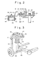
- Figure 2 is a partially sectional view of the mounting structure sectioned along II-II in Figure 1;
- Figure 3 is a perspective view showing a subassembly;
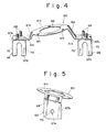
- Figure 4 is a front view of a bracket having a different shape from that shown in Figure 1 ; and
- Figure 5 is a left side view of the bracket in Figure 4.
- As shown in figure 1, in a double wishbone type suspension provided with an
upper arm 12, a shock absorber 14 and acoil spring 16, amounting structure 10 for mounting theupper arm 12, shock absorber 14 andcoil spring 16 on a car body 18 (Figure 2) includes abracket 20. - The
upper arm 12 is integrally formed with joiningportion 13a and a pair ofarm portions 13b, 13c extending inward from the joiningportion 13a and spaced in front and to the rear of one another in the longitudinal direction of the vehicle. Asteering knuckle 22 is joined with the joiningportion 13a through aball joint 24. The pair ofarm portions 13b, 13c are respectively provided at their free ends with eyes 26 (Figure 2). - The
shock absorber 14 is a twin tube type or monotube type which is well known, per se. As shown in Figure 3, theshock absorber 14 has a lower end pivotally joined with alower arm 28 and an upper end joined with thebracket 20 by a structure which will be later described. Thelower arm 28 supports thesteering knuckle 22 at an outer end thereof via a ball joint (not shown). - The
coil spring 16 is disposed to surround theshock absorber 14 and has a lower end mounted on aspring sheet 30 welded to a cylinder of theshock absorber 14. The shock absorber 14 and thecoil spring 16 are disposed in aspace 32 between thearm portions 13b, 13c of theupper arm 12. - The
bracket 20 has lateral first and second mountingportions 21a, 21b and a centralthird mounting portion 21c. These mounting portions are press formed of sheet material. Thethird mounting portion 21c is positioned above the first andsecond portions 21a, 21b and is formed in a ring-shape. - In the embodiment shown, the
bracket 20 has a pair of mountingmembers 34 fixed respectively to the first andsecond mounting portions 21a, 21b. Eachmember 34 has a U-shaped configuration as viewed from the front side.Bolts 36, two of which extend vertically through themounting member 34, are press fitted in the first and second mountingportions 21a, 21b respectively via serrations thereon or are welded thereto. Anadditional bolt 36 is centrally mounted on the bracket. Thebolts 36 connect thebracket 20 with thecar body 18 and two of a plurality of bolts preferably also fix the-mountingmembers 34. - Rubber bushings (not shown) are attached within the
respective eyes 26 inarm portions 13b and 13c of theupper arm 12. These eyes are positioned within themounting members 34, abolt 38 is inserted through each of the mounting members and bushing, and anut 40 is threaded onto each bolt, so that therespective arm portions 21a, 21b of theupper arm 12 are pivotally joined with thebracket 20. - A
piston rod 15 of the shock absorber 14 and an upper end of thecoil spring 16 connected to thethird mounting portion 21c of thebracket 20. In the embodiment shown in Figure 2, a pair ofsupport plates 44 are bonded to the central portion of arubber bushing 42 and asupport plate 46 is bonded to a peripheral edge of thebushing 42. An end of thepiston rod 15 extends through thesupport plates 44 and anut 48 is threaded onto said end. On the other hand, a plurality of bolts 50 (two bolts are shown in Figure 1) are press fitted into thesupport plate 46 via serrations thereon and extend through the third mountingportions 21c of thebracket 20 andnuts 52 are threaded respectively onto thebolts 50 to join thepiston rod 15 with thebracket 20. An upper end of thecoil spring 16 bears against the bushing 42. - As shown in Figure 3, the
upper arm 12, shock absorber 14 andcoil spring 16 are connected to thebracket 20 and an inner end of thelower arm 28 is pivotally joined with asubframe 54 to constitute asubassembly 56. The wheel alignment can be coordinated with thissubassembly 56 before incorporating the subassembly into the car body. Thebolts 36 of thebracket 20 extend through thecar body 18 andnuts 58 are respectively screwed onto thebolts 36 to join thebracket 20 thereto, thereby joining thesubassembly 56, theupper arm 12, shock absorber 14 andcoil spring 16 with the car body. - A
bracket 60 shown in the second embodiment of Figures 4 and 5 has first and second lateral mounting portions 61a, 61b on both sides thereof and a thirdcentral mounting portion 61c. These mounting portions are press formed from a sheet material. Ribs 61d extend from a step portion joining the third mounting portion with the first and second mounting portions. Thethird mounting portion 61c is formed in a ring-shape having acentral hole 62 and threeholes 64 though each of which a bolt for connecting thebracket 60 with the shock absorber extends. A support (not shown) similar to that of the first embodiment and including a rubber bushing is disposed between thebracket 60 and the shock absorber. - The
bracket 60 has a pair ofmounting members 66, each having first andsecond portions first portion 67a is bent in U-shape and formed flat at its top. The second portion 617b is a flat U-shape sheet and is welded to thefirst portion 67a. Twobolts 68 extend through thefirst portion 67a of each of the mountingmembers 66 and are press fitted in the respective mounting portion of thebracket 60 facing the flat top of thefirst portion 67a. - The
first portion 67a of the mountingmember 66 hasholes 70 on its sides. Theeye 26 of the arm portion of theupper arm 12 is disposed in a space defined by the parallel legs of the U-shapedfirst portion 67a. A bolt extends through theeye 26 and theholes 70 and a nut is screwed onto the bolt. Thus, theupper arm 12 is connected to thebracket 60. After the shock absorber and upper arm are connected with thebracket 60, thebracket 60 is mounted on the car body through the fourbolts 68. - In the aforementioned embodiments, the
upper arm 12 has twoarm portions 13b, 13c spaced in front and to the rear of each other. Instead, a so-called I type arm like thelower arm 28 in Figure 3 may be used as an upper arm. In this case, thebracket 20 has only one mounting portion for the upper arm. - The
coil spring 16 may be disposed independently of theshock absorber 14. In this case, the upper end of thecoil spring 16 is pressed not on the bracket but on the car body. - Obviously, numerous modifications and variations of the present invention are possible in light of the above teachings, it is therefore to be understood that within the scope of the appended claims, the invention may be practiced otherwise than as specifically described herein.
Claims (9)
Applications Claiming Priority (2)
| Application Number | Priority Date | Filing Date | Title |
|---|---|---|---|
| JP1985066484U JPH0351203Y2 (en) | 1985-05-07 | 1985-05-07 | |
| JP66484/85 | 1985-05-07 |
Publications (3)
| Publication Number | Publication Date |
|---|---|
| EP0201082A2 true EP0201082A2 (en) | 1986-11-12 |
| EP0201082A3 EP0201082A3 (en) | 1987-03-18 |
| EP0201082B1 EP0201082B1 (en) | 1990-12-27 |
Family
ID=13317106
Family Applications (1)
| Application Number | Title | Priority Date | Filing Date |
|---|---|---|---|
| EP86106197A Expired - Lifetime EP0201082B1 (en) | 1985-05-07 | 1986-05-06 | Mounting structure for a vehicle suspension |
Country Status (5)
| Country | Link |
|---|---|
| US (1) | US4750755A (en) |
| EP (1) | EP0201082B1 (en) |
| JP (1) | JPH0351203Y2 (en) |
| AU (1) | AU572394B2 (en) |
| DE (1) | DE3676547D1 (en) |
Cited By (3)
| Publication number | Priority date | Publication date | Assignee | Title |
|---|---|---|---|---|
| AU572394B2 (en) * | 1985-05-07 | 1988-05-05 | Toyota Jidosha Kabushiki Kaisha | Suspension mounting structure |
| EP0351376A1 (en) * | 1988-07-11 | 1990-01-17 | FIAT AUTO S.p.A. | A suspension for the front steered wheels of a motor vehicle |
| DE102022110167A1 (en) | 2022-04-27 | 2023-11-02 | Audi Aktiengesellschaft | Wheel suspension device for a motor vehicle, corresponding motor vehicle and method for assembling a motor vehicle |
Families Citing this family (9)
| Publication number | Priority date | Publication date | Assignee | Title |
|---|---|---|---|---|
| JPH0539922Y2 (en) * | 1987-05-11 | 1993-10-12 | ||
| US5375870A (en) * | 1992-12-17 | 1994-12-27 | Chrysler Corporation | Mounting structure of a front suspension system |
| US5536035A (en) * | 1995-05-15 | 1996-07-16 | General Motors Corporation | Dual suspension shock tower |
| KR100313801B1 (en) * | 1999-01-06 | 2001-11-15 | 이계안 | Rear suspension system for vehicles |
| EP1076783B1 (en) * | 1999-03-06 | 2004-06-30 | Dr. Ing. H.C.F. Porsche Aktiengesellschaft | Bearing for a shock absorber strut or a pneumatic spring |
| US6113144A (en) * | 1999-10-21 | 2000-09-05 | Dana Corporation | Two-piece upper control arm and spring mounting bracket |
| DE19954412A1 (en) | 1999-11-12 | 2001-05-17 | Audi Ag | Arrangement of a wheel suspension |
| US8448966B2 (en) * | 2011-01-05 | 2013-05-28 | Tesla Motors, Inc. | Vehicle front shock tower |
| US12415395B1 (en) * | 2024-08-19 | 2025-09-16 | Fox Factory, Inc. | Double-shear control arm mount |
Family Cites Families (17)
| Publication number | Priority date | Publication date | Assignee | Title |
|---|---|---|---|---|
| GB502644A (en) * | 1937-10-22 | 1939-03-22 | Fiat Spa | Improvements relating to independent wheel suspensions for motor vehicles |
| US2334597A (en) * | 1939-07-21 | 1943-11-16 | Hudson Motor Car Co | Wheel suspension |
| BE494404A (en) * | 1949-03-17 | |||
| DE1071500B (en) * | 1956-10-31 | |||
| US2888269A (en) * | 1956-12-12 | 1959-05-26 | Gen Motors Corp | Vehicle frame |
| DE1107524B (en) * | 1957-03-05 | 1961-05-25 | Nsu Motorenwerke Ag | Auxiliary support for the front wheel suspension on vehicles with a self-supporting body |
| US3958653A (en) * | 1970-07-06 | 1976-05-25 | Ford Motor Company | Motor vehicle chassis subassembly |
| US3927711A (en) * | 1974-01-31 | 1975-12-23 | Fisher Gauge Ltd | High pressure die casting apparatus |
| FR2465604A1 (en) * | 1979-09-20 | 1981-03-27 | Citroen Sa | OSCILLATING TELESCOPIC LEG SUSPENSION FOR VEHICLE WHEEL |
| US4318551A (en) * | 1979-09-28 | 1982-03-09 | The Model A And Model T Motor Car Reproduction Corp. | Vehicle front suspension system support |
| US4377298A (en) * | 1981-06-11 | 1983-03-22 | General Motors Corporation | Vehicle wheel suspension |
| JPS5877945A (en) * | 1981-10-31 | 1983-05-11 | Toyota Motor Corp | Upper support for suspension device |
| JPS59182407A (en) * | 1983-04-01 | 1984-10-17 | Sumitomo Electric Ind Ltd | Structure of optical fiber sensor branched part |
| JPS5996007A (en) * | 1982-11-24 | 1984-06-02 | Honda Motor Co Ltd | Suspension arm mounting structure for vehicle |
| US4486028A (en) * | 1982-12-22 | 1984-12-04 | Toyota Jidosha Kabushiki Kaisha | Upper support structure for front wheel suspension of automobile |
| US4531759A (en) * | 1983-08-04 | 1985-07-30 | General Motors Corporation | Suspension strut for vehicles with onboard service of shock absorber cartridge |
| JPH0351203Y2 (en) * | 1985-05-07 | 1991-11-01 |
-
1985
- 1985-05-07 JP JP1985066484U patent/JPH0351203Y2/ja not_active Expired
-
1986
- 1986-05-06 DE DE8686106197T patent/DE3676547D1/en not_active Expired - Lifetime
- 1986-05-06 AU AU57173/86A patent/AU572394B2/en not_active Expired
- 1986-05-06 EP EP86106197A patent/EP0201082B1/en not_active Expired - Lifetime
- 1986-05-07 US US06/860,417 patent/US4750755A/en not_active Expired - Lifetime
Cited By (3)
| Publication number | Priority date | Publication date | Assignee | Title |
|---|---|---|---|---|
| AU572394B2 (en) * | 1985-05-07 | 1988-05-05 | Toyota Jidosha Kabushiki Kaisha | Suspension mounting structure |
| EP0351376A1 (en) * | 1988-07-11 | 1990-01-17 | FIAT AUTO S.p.A. | A suspension for the front steered wheels of a motor vehicle |
| DE102022110167A1 (en) | 2022-04-27 | 2023-11-02 | Audi Aktiengesellschaft | Wheel suspension device for a motor vehicle, corresponding motor vehicle and method for assembling a motor vehicle |
Also Published As
| Publication number | Publication date |
|---|---|
| AU5717386A (en) | 1986-11-13 |
| DE3676547D1 (en) | 1991-02-07 |
| JPS61182307U (en) | 1986-11-13 |
| US4750755A (en) | 1988-06-14 |
| JPH0351203Y2 (en) | 1991-11-01 |
| AU572394B2 (en) | 1988-05-05 |
| EP0201082A3 (en) | 1987-03-18 |
| EP0201082B1 (en) | 1990-12-27 |
Similar Documents
| Publication | Publication Date | Title |
|---|---|---|
| US6398262B1 (en) | Modular subframe assembly for a motor vehicle | |
| EP1982856A1 (en) | Automobile body frame structure | |
| US4750755A (en) | Mounting structure of an upper suspension arm and a McPherson strut | |
| CA2389140C (en) | Suspension structure | |
| JPS6044161B2 (en) | Suspension method | |
| KR100457316B1 (en) | Front whell suspension system using steering gear frame | |
| AU716456B2 (en) | Trailing arm suspension with articulated axle mounting | |
| JPH10258763A (en) | Suspension subframe structure | |
| US6089582A (en) | Strut wheel suspension system | |
| JP3128678B2 (en) | Mounting structure of shock absorber | |
| KR100330042B1 (en) | Knuckle bracket structure of vehicle shock absorber | |
| JPH0452082Y2 (en) | ||
| JP3165944B2 (en) | Independent suspension | |
| JP3200854B2 (en) | Method of assembling steering wheel suspension | |
| CN220948170U (en) | Frame-shaped multi-connecting-rod rear auxiliary frame welding assembly | |
| KR200206928Y1 (en) | Lower control arm of car suspension | |
| JP3264416B2 (en) | Mounting bracket for hydraulic shock absorber | |
| JPH067934Y2 (en) | Suspension mounting structure | |
| JPH07186652A (en) | Fixing structure of shaft member in suspension member made of light alloy | |
| JP2592016Y2 (en) | Suspension link coupling device | |
| JPH065956Y2 (en) | Vehicle body frame | |
| JP3238263B2 (en) | Fixing structure of shaft member in light alloy suspension member | |
| JP3033800B2 (en) | Suspension mounting method and its mounting jig | |
| JPH067933Y2 (en) | Suspension mounting structure | |
| KR200206035Y1 (en) | Knuckle bracket structure for a strut |
Legal Events
| Date | Code | Title | Description |
|---|---|---|---|
| PUAI | Public reference made under article 153(3) epc to a published international application that has entered the european phase |
Free format text: ORIGINAL CODE: 0009012 |
|
| AK | Designated contracting states |
Kind code of ref document: A2 Designated state(s): DE FR GB |
|
| PUAL | Search report despatched |
Free format text: ORIGINAL CODE: 0009013 |
|
| AK | Designated contracting states |
Kind code of ref document: A3 Designated state(s): DE FR GB |
|
| 17P | Request for examination filed |
Effective date: 19870917 |
|
| 17Q | First examination report despatched |
Effective date: 19890406 |
|
| GRAA | (expected) grant |
Free format text: ORIGINAL CODE: 0009210 |
|
| AK | Designated contracting states |
Kind code of ref document: B1 Designated state(s): DE FR GB |
|
| ET | Fr: translation filed | ||
| REF | Corresponds to: |
Ref document number: 3676547 Country of ref document: DE Date of ref document: 19910207 |
|
| PLBE | No opposition filed within time limit |
Free format text: ORIGINAL CODE: 0009261 |
|
| STAA | Information on the status of an ep patent application or granted ep patent |
Free format text: STATUS: NO OPPOSITION FILED WITHIN TIME LIMIT |
|
| 26N | No opposition filed | ||
| REG | Reference to a national code |
Ref country code: GB Ref legal event code: IF02 |
|
| REG | Reference to a national code |
Ref country code: GB Ref legal event code: 746 Effective date: 20040505 |
|
| REG | Reference to a national code |
Ref country code: GB Ref legal event code: 746 Effective date: 20040507 |
|
| REG | Reference to a national code |
Ref country code: FR Ref legal event code: D6 |
|
| PGFP | Annual fee paid to national office [announced via postgrant information from national office to epo] |
Ref country code: DE Payment date: 20050428 Year of fee payment: 20 |
|
| PGFP | Annual fee paid to national office [announced via postgrant information from national office to epo] |
Ref country code: GB Payment date: 20050504 Year of fee payment: 20 |
|
| PGFP | Annual fee paid to national office [announced via postgrant information from national office to epo] |
Ref country code: FR Payment date: 20050511 Year of fee payment: 20 |
|
| PG25 | Lapsed in a contracting state [announced via postgrant information from national office to epo] |
Ref country code: GB Free format text: LAPSE BECAUSE OF EXPIRATION OF PROTECTION Effective date: 20060505 |
|
| REG | Reference to a national code |
Ref country code: GB Ref legal event code: PE20 |