EP0201115B1 - Eintragvorrichtung für stark abreibendes Material - Google Patents
Eintragvorrichtung für stark abreibendes Material Download PDFInfo
- Publication number
- EP0201115B1 EP0201115B1 EP86200501A EP86200501A EP0201115B1 EP 0201115 B1 EP0201115 B1 EP 0201115B1 EP 86200501 A EP86200501 A EP 86200501A EP 86200501 A EP86200501 A EP 86200501A EP 0201115 B1 EP0201115 B1 EP 0201115B1
- Authority
- EP
- European Patent Office
- Prior art keywords
- impeller
- compartments
- housing
- feeder
- set forth
- Prior art date
- Legal status (The legal status is an assumption and is not a legal conclusion. Google has not performed a legal analysis and makes no representation as to the accuracy of the status listed.)
- Expired
Links
- 239000003082 abrasive agent Substances 0.000 title claims description 12
- 239000000463 material Substances 0.000 claims description 34
- 238000005299 abrasion Methods 0.000 claims description 3
- 238000007789 sealing Methods 0.000 claims description 2
- PNEYBMLMFCGWSK-UHFFFAOYSA-N aluminium oxide Inorganic materials [O-2].[O-2].[O-2].[Al+3].[Al+3] PNEYBMLMFCGWSK-UHFFFAOYSA-N 0.000 description 9
- 229910052782 aluminium Inorganic materials 0.000 description 6
- XAGFODPZIPBFFR-UHFFFAOYSA-N aluminium Chemical compound [Al] XAGFODPZIPBFFR-UHFFFAOYSA-N 0.000 description 6
- 239000007789 gas Substances 0.000 description 6
- 239000002245 particle Substances 0.000 description 6
- 238000004519 manufacturing process Methods 0.000 description 4
- 238000004140 cleaning Methods 0.000 description 3
- 230000001276 controlling effect Effects 0.000 description 3
- 150000002222 fluorine compounds Chemical class 0.000 description 3
- 238000011084 recovery Methods 0.000 description 3
- CURLTUGMZLYLDI-UHFFFAOYSA-N Carbon dioxide Chemical compound O=C=O CURLTUGMZLYLDI-UHFFFAOYSA-N 0.000 description 2
- KRHYYFGTRYWZRS-UHFFFAOYSA-N Fluorane Chemical compound F KRHYYFGTRYWZRS-UHFFFAOYSA-N 0.000 description 2
- KRHYYFGTRYWZRS-UHFFFAOYSA-M Fluoride anion Chemical compound [F-] KRHYYFGTRYWZRS-UHFFFAOYSA-M 0.000 description 2
- RAHZWNYVWXNFOC-UHFFFAOYSA-N Sulphur dioxide Chemical compound O=S=O RAHZWNYVWXNFOC-UHFFFAOYSA-N 0.000 description 2
- 238000001033 granulometry Methods 0.000 description 2
- 229930195733 hydrocarbon Natural products 0.000 description 2
- 150000002430 hydrocarbons Chemical class 0.000 description 2
- 229910000040 hydrogen fluoride Inorganic materials 0.000 description 2
- 230000001788 irregular Effects 0.000 description 2
- 238000000034 method Methods 0.000 description 2
- 239000002912 waste gas Substances 0.000 description 2
- OKTJSMMVPCPJKN-UHFFFAOYSA-N Carbon Chemical compound [C] OKTJSMMVPCPJKN-UHFFFAOYSA-N 0.000 description 1
- UGFAIRIUMAVXCW-UHFFFAOYSA-N Carbon monoxide Chemical compound [O+]#[C-] UGFAIRIUMAVXCW-UHFFFAOYSA-N 0.000 description 1
- 229910052799 carbon Inorganic materials 0.000 description 1
- 229910002092 carbon dioxide Inorganic materials 0.000 description 1
- 239000001569 carbon dioxide Substances 0.000 description 1
- 229910002091 carbon monoxide Inorganic materials 0.000 description 1
- 238000010276 construction Methods 0.000 description 1
- 238000006073 displacement reaction Methods 0.000 description 1
- 239000003344 environmental pollutant Substances 0.000 description 1
- 239000003517 fume Substances 0.000 description 1
- 229910052751 metal Inorganic materials 0.000 description 1
- 239000002184 metal Substances 0.000 description 1
- 231100000719 pollutant Toxicity 0.000 description 1
- 230000001105 regulatory effect Effects 0.000 description 1
- 239000007787 solid Substances 0.000 description 1
- 238000001179 sorption measurement Methods 0.000 description 1
- 239000002699 waste material Substances 0.000 description 1
Images
Classifications
-
- B—PERFORMING OPERATIONS; TRANSPORTING
- B65—CONVEYING; PACKING; STORING; HANDLING THIN OR FILAMENTARY MATERIAL
- B65G—TRANSPORT OR STORAGE DEVICES, e.g. CONVEYORS FOR LOADING OR TIPPING, SHOP CONVEYOR SYSTEMS OR PNEUMATIC TUBE CONVEYORS
- B65G65/00—Loading or unloading
- B65G65/30—Methods or devices for filling or emptying bunkers, hoppers, tanks, or like containers, of interest apart from their use in particular chemical or physical processes or their application in particular machines, e.g. not covered by a single other subclass
- B65G65/34—Emptying devices
- B65G65/40—Devices for emptying otherwise than from the top
- B65G65/48—Devices for emptying otherwise than from the top using other rotating means, e.g. rotating pressure sluices in pneumatic systems
- B65G65/4809—Devices for emptying otherwise than from the top using other rotating means, e.g. rotating pressure sluices in pneumatic systems rotating about a substantially vertical axis
- B65G65/4836—Devices for emptying otherwise than from the top using other rotating means, e.g. rotating pressure sluices in pneumatic systems rotating about a substantially vertical axis and moving material over a stationary surface, e.g. sweep arms or wheels
Definitions
- This invention relates to feeders and more particularly to feeders for handling highly abrasive materials as outlined in the first part of claim 1.
- a feeder of similar construction is disclosed in DE-A-3 335 860.
- volumetric and gravimetric feeders have been widely used for controlling the feed rate of materials used in various industrial applications. While a wide variety of feeder types have been employed, the choice is normally governed by the properties and characteristics of the material whose feed rate is to be controlled and the requirements of the specific application. For example, the material may vary in granulometry from a few microns in particle size up to 10 and 20 millimeters or more. In addition, the material particle may be uniform in size and shape or irregular or may vary in abrasiveness. Another variable is the feed accuracy required by the specific application. In some cases, relatively accurate and uniform flow rates may be required while other applications may permit fluctuations of up to 5 or 10 percent from the nominal required value.
- prior art volumetric and gravimetric feeders include Archimedean screws, multiple rotary vane and vibratory types.
- Various probelms have been encounted in employing prior art feeders resulting from a combination of the characteristics of the material being fed and the constraints or requirements imposed by the specific application. These problems include inaccuarate or irregular flow rates usually effected by changes in material granulometry or fluidity, changes of material head column at the inlet of the feeder and changes of relative pressure or air currents across the feeder in applications where the feeder is connected to processes or ducts under pressure.
- Some prior art feeders are also susceptible to self-destruction by overload when the discharge material exit from the feeder is blocked. This occurs when the apparatus and drive train forces material against a dead head or blocked exit.
- metal grade alumina is employed for the adsorption and removal of hydrogen fluoride and other fluoride compounds as well as the entrapment of hydrocarbons from gases evolved in the aluminum manufacturing process.
- the principle advantage of using alumina for pollution control and material recovery is that the alumina along with the recovered fluoride can readily be returned to the reduction pots or cells, for use in the aluminum recovery process.
- alumina is fed at a controlled rate into a horizontal or vertical duct through which the waste gases are conducted.
- the alumina particles are dispersed into the waste stream for the adsportion of fluorine compounds.
- Another object of the invention is to provide a feeder for highly abrasive materials wherein the material is segregated from the apparatus drive components.
- a further object of the invention is to provide a feeder for use with abrasive particles wherein abrasion of drive components is minimized.
- Yet another object of the invention is to provide a volumetric feeder for highly abrasive material wherein relative movement between the material and the apparatus is minimized.
- the invention comprises a feeder for a highly abrasive materials, which includes a housing having upper and lower wall portions.
- An impeller is disposed within the housing and includes means defining a plurality of compartments of equal volume and disposed in an equi-angular circular array. The compartments are disposed adjacent the lower end of the housing and are open at their upper and lower ends.
- the impeller also includes an upper portion disposed above the compartments and adjacent the upper wall portion of the housing.
- Shaft means extends downwardly through the upper wall portion and engages the upper portion of the impeller and drive means is coupled to the shaft means for rotating the impeller at a controlled rate of speed.
- Feeding means extends into the housing and has a lower end terminating above a circular path defined by the upper ends of the compartments whereby material fed through the feeding means will flow into a compartment disposed therebelow.
- An opening is formed in the bottom wall portion and displaced from the feeding means so that material fed through the feeding means will fall into successive compartments as the impeller is rotated with the material being carried sequentially by the compartments to a position over the bottom opening whereby the material will be discharged through the opening at a controlled rate.
- the abrasive material is carried by the compartments so that there is no relative movement between the material and the impeller and the material does not contact the housing. Additionally, the shaft drive components of the impeller remain out of contact with the abrasive material.
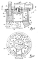
- the feeder 10 according to the preferred embodiment of the invention is shown in the drawings to include a feeder housing 12, an impeller 14 rotatably mounted within housing 12 and a drive 16 for rotating the impeller at a speed governed by the desired feed rate.
- the housing 12 includes a cylindrical, vertically oriented outer wall portion 18 and a cylindrical, vertically oriented inner wall portion 20 which is spaced from and concentric with respect to the outer wall portion 18.
- the lower edges of the wall portions 18 and 20 are coplanar and closed by a common bottom plate 22 except for an opening 24 in one side of plate 22 and between the wall portions 18 and 20.
- a discharge chute 26 is fixed to bottom plate 22 in surrounding relation to opening 24 and extends downwardly and laterally outwardly therefrom.
- the outer wall portion 18 is also closed by a top plate 28.
- the inner wall portion 20 is shorter than the outer wall portion 18 and is closed by a top plate 30 so that a gap exists beween the plates 28 and 30.
- the impeller 14 is generally annular and is disposed in the gap between the wall portions 18 and 20 and the plates 28 and 30.
- impeller 14 includes a first, hollow, open-ended cylindrical member 34 disposed coaxially with respect to the wall portions 18 and 20 and having a diameter and height slightly smaller than that of wall portion 18.
- a second smaller diameter cylindrical member 36 is disposed concentrically within the cylinder member 34.
- the members 34 and 36 are of equal height and their upper and lower ends lie in respective parallel planes.
- a plurality of equi-spaced, generally rectangularly shaped, radially extending fins 38 extend between and join the members 34 and 36.
- the fins 38 extend upwardly from the lower edges of the members 34 and 36 and are coequal in height but shorter than the members 34 and 36 and define a plurality of compartments 40 which are equal in volume.
- a circular top plate 41 is fixed to the upper edge of member 36 and has an axial hub 42 which is secured in any suitable manner, such as by a set screw 43, to a shaft 44 extending downwardly through an opening 45 in the plate 28 and from the drive 16.
- a seal 46 surrounds opening 45 and the shaft 44 is supported in a bearing 47.
- the impeller is thus supported by the shaft 44 so that the lower edges of the cylindrical members 34 and 36 are positioned in close proximity to, but spaced a short distance above, the bottom plate 22.
- the drive includes a variable speed motor 48 and a gear reduction unit 49 from which the shaft 44 extends.
- the top plate 28 has an opening 50 disposed above the gap between cylindrical members 34 and 36 and on the side of housing 12 opposite to the discharge chute 26.
- a feed spout 52 extends through opening 50 and has its lower edge positioned a short distance above the plane containing the upper edges of the fins 38.
- a flange 54 extends radially outwardly from spout 52 and is suitably secured to plate 28 for supporting the spout 52 and sealing the opening 50.
- the feeder 10 is mounted on a support plate 56 by means of a pivot base 58 which includes a first pivot member 59 secured to the lower surface of bottom plate 22 and a second pivot member 60 secured to the support plate 56.
- the members 59 and 60 are joined by a pivot pin 62 whose axis 63 is perpendicular to the axis of spout 52.
- a strain gauge 65 is positioned along the axis of the shaft 44 and is connected at its opposite ends by a first pivot 66 to the plate 22 and by a second pivot 67 to the support plate 56. Strain gauge 65 may be connected to any suitable indicating device so that the weight of material 72 in the feeder 10 can be determined.
- the motor 49 is energized to rotate the impeller 14 at a controlled rate of speed.
- Material 72 such as alumina, is fed downwardly through the spout 52 and into successive compartments 40 passing therebelow as the rotor 14 rotates.
- the amount of material 72 that is deposited in each successive compartment 40 depends upon the rate at which material is fed through the spout 52 and the rate at which the impeller 14 is rotated. Normally the material 72 is fed through spout 52 at a constant rate and the feed rate of the system is regulated by controlling the motor speed.
- the shaft 44, the seal 46 and the bearing 47 are all located above and spaced from the compartments 40 in the lower end of the housing. As a result, the shaft 44, the seal 46 and the bearings 47 are substantially free of contact by the highly abrasive material 72.
- the material 72 is carried in the compartments 40 as the impeller 14 rotates, there is little relative motion between the material and the impeller 14 or the housing 12.
- the layer of material 72 on the plate 22 isolates the material carried by the compartment 40 from the plate 22. As a result, wear on these components is also minimized.
- the rate at which the material is fed from the chute 26 can be accurately controlled by controlling the rate at which the impeller 14 rotates.
Landscapes
- Engineering & Computer Science (AREA)
- Mechanical Engineering (AREA)
- Filling Or Emptying Of Bunkers, Hoppers, And Tanks (AREA)
- Finish Polishing, Edge Sharpening, And Grinding By Specific Grinding Devices (AREA)
- Polishing Bodies And Polishing Tools (AREA)
Claims (7)
Applications Claiming Priority (2)
| Application Number | Priority Date | Filing Date | Title |
|---|---|---|---|
| US06/732,180 US4685593A (en) | 1985-05-08 | 1985-05-08 | Feeder for highly abrasive materials |
| US732180 | 1985-05-08 |
Publications (3)
| Publication Number | Publication Date |
|---|---|
| EP0201115A2 EP0201115A2 (de) | 1986-11-12 |
| EP0201115A3 EP0201115A3 (en) | 1987-08-05 |
| EP0201115B1 true EP0201115B1 (de) | 1989-09-27 |
Family
ID=24942501
Family Applications (1)
| Application Number | Title | Priority Date | Filing Date |
|---|---|---|---|
| EP86200501A Expired EP0201115B1 (de) | 1985-05-08 | 1986-03-25 | Eintragvorrichtung für stark abreibendes Material |
Country Status (10)
| Country | Link |
|---|---|
| US (1) | US4685593A (de) |
| EP (1) | EP0201115B1 (de) |
| JP (1) | JPH0811627B2 (de) |
| CN (1) | CN1010219B (de) |
| AU (1) | AU583360B2 (de) |
| CA (1) | CA1292208C (de) |
| DE (1) | DE3665850D1 (de) |
| ES (1) | ES8702854A1 (de) |
| MX (1) | MX165742B (de) |
| NO (1) | NO163049C (de) |
Families Citing this family (8)
| Publication number | Priority date | Publication date | Assignee | Title |
|---|---|---|---|---|
| US5288479A (en) | 1989-01-17 | 1994-02-22 | Sterling Drug, Inc. | Extrudable elastic oral pharmaceutical gel compositions and metered dose dispensers containing them and method of making and method of use thereof |
| IT1232499B (it) * | 1989-08-09 | 1992-02-17 | Zanasi Nuova Spa | Tramoggia per prodotti polverulenti di diversa fluidita', atta ad alimentare selettivamente o contemporaneamente piu' dosatori a tamburo rotante che operano al di sotto della stessa tramoggia |
| US5833092A (en) * | 1997-02-20 | 1998-11-10 | Summit Machine Builders, Corp. | Apparatus for feeding poorly flowable dry particulate materials |
| US6071523A (en) * | 1998-06-03 | 2000-06-06 | Taro Pharmaceuticals Industries, Ltd. | Spill resistant pharmaceutical compositions in semi-solid form |
| CN1970409B (zh) * | 2006-12-08 | 2010-08-11 | 陆昕 | 全自动定量给料机 |
| CN105016032B (zh) * | 2014-04-15 | 2018-07-20 | 藤原酿造机械株式会社 | 立式旋转阀 |
| CN112640843B (zh) * | 2020-12-22 | 2022-10-28 | 江西正邦科技股份有限公司 | 一种减少断奶仔猪掉膘的方法 |
| CN120538037A (zh) * | 2025-07-24 | 2025-08-26 | 山西省安装集团股份有限公司 | 一种循环流化床炉内脱硝系统输送尿素防堵装置 |
Family Cites Families (19)
| Publication number | Priority date | Publication date | Assignee | Title |
|---|---|---|---|---|
| US789085A (en) * | 1902-06-28 | 1905-05-02 | Joseph H Dary | Bagging-machine. |
| US1184074A (en) * | 1915-02-10 | 1916-05-23 | Harry A Clark | Sanitary loaf-sugar dispenser. |
| US2199065A (en) * | 1938-04-20 | 1940-04-30 | E H Sieling | Dispensing and measuring machine |
| US2610646A (en) * | 1950-06-29 | 1952-09-16 | United States Steel Corp | Proportioning distributor for mineral pulp or the like |
| US2942761A (en) * | 1958-03-17 | 1960-06-28 | Fr Hesser Maschinenfabrik Ag F | Dispensing machine |
| US3101872A (en) * | 1960-06-24 | 1963-08-27 | Continental Vending Machine Co | Ice storing and dispensing mechanism for beverage dispensing machines and the like |
| US3102665A (en) * | 1960-09-16 | 1963-09-03 | Degussa | Devices for transferring particulate solids |
| US3251511A (en) * | 1964-05-20 | 1966-05-17 | Roger A Lloyd | Rotary valve |
| US3260415A (en) * | 1964-07-13 | 1966-07-12 | Takeda Chemical Industries Ltd | Particulate solid material discharge apparatus |
| US3265251A (en) * | 1965-02-01 | 1966-08-09 | Bartelt Engineering Co Inc | Measuring and dispensing device |
| US3305139A (en) * | 1965-04-12 | 1967-02-21 | Wallace W Ward | Powdered material dispenser |
| US3406871A (en) * | 1965-06-24 | 1968-10-22 | King Seeley Thermos Co | Flaked ice dispenser |
| US3374811A (en) * | 1965-08-12 | 1968-03-26 | Frederick Z. Goosman | Liquid measuring and dispensing apparatus |
| DE1920840A1 (de) * | 1969-04-24 | 1970-11-05 | Braun Ag | Dosiervorrichtung |
| US3716167A (en) * | 1971-03-15 | 1973-02-13 | Galigher Co | Rotary sample collector |
| JPS5820595Y2 (ja) * | 1978-11-01 | 1983-04-28 | 株式会社日立製作所 | 真空装置へ原料を供給する装置 |
| JPS5980321U (ja) * | 1982-11-24 | 1984-05-30 | クラレケミカル株式会社 | 粒状物取出装置 |
| US4613058A (en) * | 1983-02-07 | 1986-09-23 | Conger Roger C | Rotary volumetric loading meter |
| DE3335860A1 (de) * | 1983-10-03 | 1985-04-18 | Klöckner-Humboldt-Deutz AG, 5000 Köln | Vorrichtung und arbeitsverfahren zum ausschleusen von materialien aus druckbehaeltern |
-
1985
- 1985-05-08 US US06/732,180 patent/US4685593A/en not_active Expired - Lifetime
-
1986
- 1986-03-14 CA CA000504183A patent/CA1292208C/en not_active Expired - Lifetime
- 1986-03-17 AU AU54778/86A patent/AU583360B2/en not_active Expired
- 1986-03-25 EP EP86200501A patent/EP0201115B1/de not_active Expired
- 1986-03-25 DE DE8686200501T patent/DE3665850D1/de not_active Expired
- 1986-04-12 CN CN86102607.1A patent/CN1010219B/zh not_active Expired
- 1986-04-14 MX MX002160A patent/MX165742B/es unknown
- 1986-04-26 ES ES554410A patent/ES8702854A1/es not_active Expired
- 1986-05-07 NO NO861831A patent/NO163049C/no unknown
- 1986-05-07 JP JP61103234A patent/JPH0811627B2/ja not_active Expired - Lifetime
Also Published As
| Publication number | Publication date |
|---|---|
| JPH0811627B2 (ja) | 1996-02-07 |
| ES554410A0 (es) | 1987-01-16 |
| JPS61257835A (ja) | 1986-11-15 |
| DE3665850D1 (en) | 1989-11-02 |
| NO163049B (no) | 1989-12-18 |
| AU5477886A (en) | 1986-11-13 |
| NO163049C (no) | 1990-03-28 |
| ES8702854A1 (es) | 1987-01-16 |
| US4685593A (en) | 1987-08-11 |
| EP0201115A3 (en) | 1987-08-05 |
| CA1292208C (en) | 1991-11-19 |
| CN1010219B (zh) | 1990-10-31 |
| EP0201115A2 (de) | 1986-11-12 |
| MX165742B (es) | 1992-12-03 |
| NO861831L (no) | 1986-11-10 |
| AU583360B2 (en) | 1989-04-27 |
| CN86102607A (zh) | 1986-12-17 |
Similar Documents
| Publication | Publication Date | Title |
|---|---|---|
| EP0201115B1 (de) | Eintragvorrichtung für stark abreibendes Material | |
| KR102559996B1 (ko) | 분체 처리 장치 | |
| JP2509374B2 (ja) | 粉粒体分級装置 | |
| US3574411A (en) | Side inlet rotary valve | |
| KR890002073B1 (ko) | 입상물질 분리기 | |
| JP7128854B2 (ja) | 分級装置 | |
| CN101961687B (zh) | 动力旋分器 | |
| CN86100993A (zh) | 用于真空离心式粉碎机的固体颗粒抛射装置 | |
| US3010610A (en) | Solids flow control device and method | |
| CN85107923A (zh) | 立式磨碎机 | |
| JP2741801B2 (ja) | 粉体の分割採取装置 | |
| Hochrainer et al. | Sizing of aerosol particles by centrifugation | |
| JP2946231B2 (ja) | 超微粉分級機 | |
| CN201454706U (zh) | 动力旋分器 | |
| US4813480A (en) | Apparatus for cooling dust or finely granular bulk material | |
| FI81739C (fi) | Anordning foer klassificering eller separering av fasta aemnen. | |
| SU1510961A1 (ru) | Центробежный классификатор | |
| EP1534418B1 (de) | Verdichten von schüttgut | |
| JP2664061B2 (ja) | 空気分級機 | |
| CN114486610B (zh) | 旋流式机制砂颗粒级配分析在线快速检测系统及分析检测方法 | |
| CN214766809U (zh) | 煤炭四层筛分自动化分流系统 | |
| JPH07133027A (ja) | 粉粒体の定量移送装置 | |
| SU984508A1 (ru) | Устройство дл классификации твердых материалов по крупности в воздушном потоке | |
| SU1222330A1 (ru) | Устройство дл сортировки зернистых материалов | |
| SU1516890A2 (ru) | Прибор дл определени дисперсности частиц пыли |
Legal Events
| Date | Code | Title | Description |
|---|---|---|---|
| PUAI | Public reference made under article 153(3) epc to a published international application that has entered the european phase |
Free format text: ORIGINAL CODE: 0009012 |
|
| AK | Designated contracting states |
Kind code of ref document: A2 Designated state(s): DE FR GB IT |
|
| PUAL | Search report despatched |
Free format text: ORIGINAL CODE: 0009013 |
|
| AK | Designated contracting states |
Kind code of ref document: A3 Designated state(s): DE FR GB IT |
|
| 17P | Request for examination filed |
Effective date: 19871119 |
|
| 17Q | First examination report despatched |
Effective date: 19890203 |
|
| GRAA | (expected) grant |
Free format text: ORIGINAL CODE: 0009210 |
|
| AK | Designated contracting states |
Kind code of ref document: B1 Designated state(s): DE FR GB IT |
|
| REF | Corresponds to: |
Ref document number: 3665850 Country of ref document: DE Date of ref document: 19891102 |
|
| ITF | It: translation for a ep patent filed | ||
| ET | Fr: translation filed | ||
| PLBE | No opposition filed within time limit |
Free format text: ORIGINAL CODE: 0009261 |
|
| STAA | Information on the status of an ep patent application or granted ep patent |
Free format text: STATUS: NO OPPOSITION FILED WITHIN TIME LIMIT |
|
| 26N | No opposition filed | ||
| ITTA | It: last paid annual fee | ||
| REG | Reference to a national code |
Ref country code: GB Ref legal event code: IF02 |
|
| PGFP | Annual fee paid to national office [announced via postgrant information from national office to epo] |
Ref country code: GB Payment date: 20050316 Year of fee payment: 20 |
|
| PGFP | Annual fee paid to national office [announced via postgrant information from national office to epo] |
Ref country code: FR Payment date: 20050321 Year of fee payment: 20 |
|
| PGFP | Annual fee paid to national office [announced via postgrant information from national office to epo] |
Ref country code: IT Payment date: 20050330 Year of fee payment: 20 |
|
| PGFP | Annual fee paid to national office [announced via postgrant information from national office to epo] |
Ref country code: DE Payment date: 20050502 Year of fee payment: 20 |
|
| PG25 | Lapsed in a contracting state [announced via postgrant information from national office to epo] |
Ref country code: GB Free format text: LAPSE BECAUSE OF EXPIRATION OF PROTECTION Effective date: 20060324 |
|
| REG | Reference to a national code |
Ref country code: GB Ref legal event code: PE20 |