EP0201120A1 - Dispositif pour l'alimentation automatique d'une machine à dresser à voies multiples placée en aval d'un refroidisseur - Google Patents
Dispositif pour l'alimentation automatique d'une machine à dresser à voies multiples placée en aval d'un refroidisseur Download PDFInfo
- Publication number
- EP0201120A1 EP0201120A1 EP86200644A EP86200644A EP0201120A1 EP 0201120 A1 EP0201120 A1 EP 0201120A1 EP 86200644 A EP86200644 A EP 86200644A EP 86200644 A EP86200644 A EP 86200644A EP 0201120 A1 EP0201120 A1 EP 0201120A1
- Authority
- EP
- European Patent Office
- Prior art keywords
- sections
- unit
- straightening machine
- layer
- cooling plate
- Prior art date
- Legal status (The legal status is an assumption and is not a legal conclusion. Google has not performed a legal analysis and makes no representation as to the accuracy of the status listed.)
- Granted
Links
Images
Classifications
-
- B—PERFORMING OPERATIONS; TRANSPORTING
- B21—MECHANICAL METAL-WORKING WITHOUT ESSENTIALLY REMOVING MATERIAL; PUNCHING METAL
- B21D—WORKING OR PROCESSING OF SHEET METAL OR METAL TUBES, RODS OR PROFILES WITHOUT ESSENTIALLY REMOVING MATERIAL; PUNCHING METAL
- B21D43/00—Feeding, positioning or storing devices combined with, or arranged in, or specially adapted for use in connection with, apparatus for working or processing sheet metal, metal tubes or metal profiles; Associations therewith of cutting devices
- B21D43/006—Feeding elongated articles, such as tubes, bars, or profiles
-
- B—PERFORMING OPERATIONS; TRANSPORTING
- B21—MECHANICAL METAL-WORKING WITHOUT ESSENTIALLY REMOVING MATERIAL; PUNCHING METAL
- B21B—ROLLING OF METAL
- B21B15/00—Arrangements for performing additional metal-working operations specially combined with or arranged in, or specially adapted for use in connection with, metal-rolling mills
-
- B—PERFORMING OPERATIONS; TRANSPORTING
- B21—MECHANICAL METAL-WORKING WITHOUT ESSENTIALLY REMOVING MATERIAL; PUNCHING METAL
- B21B—ROLLING OF METAL
- B21B43/00—Cooling beds, whether stationary or moving; Means specially associated with cooling beds, e.g. for braking work or for transferring it to or from the bed
- B21B43/006—Transfer from bed
-
- B—PERFORMING OPERATIONS; TRANSPORTING
- B21—MECHANICAL METAL-WORKING WITHOUT ESSENTIALLY REMOVING MATERIAL; PUNCHING METAL
- B21B—ROLLING OF METAL
- B21B15/00—Arrangements for performing additional metal-working operations specially combined with or arranged in, or specially adapted for use in connection with, metal-rolling mills
- B21B2015/0071—Levelling the rolled product
-
- B—PERFORMING OPERATIONS; TRANSPORTING
- B21—MECHANICAL METAL-WORKING WITHOUT ESSENTIALLY REMOVING MATERIAL; PUNCHING METAL
- B21B—ROLLING OF METAL
- B21B43/00—Cooling beds, whether stationary or moving; Means specially associated with cooling beds, e.g. for braking work or for transferring it to or from the bed
- B21B43/12—Devices for positioning workpieces "flushed", i.e. with all their axial ends arranged in line on cooling beds or on co-operating conveyors, e.g. before cutting
Definitions
- the invention concerns also a device that carries out such procedure.
- GB-A-2,026,973 discloses a system for the lateral movement of bars from a cooling plate, with a build-up of bars at one end of such plate.
- FR-A-1.533.392 (Compagnie des ijks et Forge de la Loire) discloses the alignment of rolled stock at the inlet of a cooling plate by means of abutments positioned on a roller conveyor. This serves to deposit segments of one billet which are aligned with each other but are staggered in relat.ion to segments of a different billet which are aligned with each other.
- Such device also has to enable the correct positioning of the sections and the guiding of the same to be controlled constantly.
- a unit to form layers step by step is provided immediately downstream of the cooling plate.
- Such unit comprises a series of supports able to move step by step and t.o take one section at a time from the cooling plate and also able to move by a distance enough to provide the desired spacing from the next section taken. All or a portion of such supports may possibly be magnetized.
- the invention may arrange that means which orient the sections cooperate with the cooling plate; such means may be employed, for instance, where the sections are positioned at random right-side-up or upside-down on the cooling plate or with a random orientation.
- the unit that forms layers comprises two series of supports or carriages able to move step by step crosswise to the sections and equipped with means that align the sections.
- the lay-out of such support carriages is such that, when one series of carriages is fully forward, the other series is fully retracted, or viceversa.
- the transfer unit consists of a carriage able to move crosswise to the sections and bearing vertically movable supports which withdraw and deposit the sections.
- Such supports in turn can comprise alignment means, and all or a part of such supports can also be magnetized.
- Such transfer supports withdraw the sections equally spaced apart and aligned in correspondence with the unit that forms layers, and transfer them laterally and deposit them on the feeder unit.
- the feeder unit consists of a conveyor with powered rollers in line with the straightening machine. At least some of such rollers may possibly be magnetized so as to prevent undesired jerking of the sections being fed.
- the invention overcomes the problem of providing constant guiding of the sections fed to the straightening machine by including a lead-in unit, which comprises guides, such as stationary channel guides cooperating with specially shaped roller guides, such guides being able to improve the spacing imparted to the layer of sections and to maintain such spacing throughout the whole sliding of the sections from the roller conveyor line to the straightening machine itself.
- guides such as stationary channel guides cooperating with specially shaped roller guides, such guides being able to improve the spacing imparted to the layer of sections and to maintain such spacing throughout the whole sliding of the sections from the roller conveyor line to the straightening machine itself.
- the lead-in unit comprises at least one pair of rollers able to move in relation to each other so as to enable the sections to be readily introduced laterally and such rollers to be clamped thereafter on the sections.
- a guide consisting of a multi-channel panel cooperates with such rollers momentarily so as to provide a final spacing of the sections and to guide the sections when they are sliding.
- Such guide is normally raised so as to permit lateral introduction of the layer of sections.
- a specially shaped guide roller is also included immediately upstream of the rollers of the straightening machine and cooperates with the cited pair of rollers of the lead-in unit.
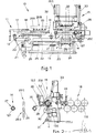
- a feed device 10 is located immediately downstream of a cooling plate 11, stationary blades 17 and movable blades 18 of which can be seen.
- the cooling plate 11 is embodied in a known manner.
- a unit 12 which forms layers cooperates with the cooling plate 11 and comprises two series of support carriages 19-119 that form layers. These series of support carriages 19-119 can slide along guides 20 arranged crosswise to rolled sections 35.
- Such sections which have been butted beforehand in a known manner. are moved from the cooling plate 11 to the support carriages 19-119 by the movement of the movable blades 18.
- the support carriages 19-119 are driven in this example by chains 21, but equivalent actuation means of any type may be provided.
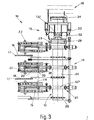
- Figs.l and 3 show a transfer unit 13, which in this example comprises a carriage 24 able to slide on guides 25 of a frame 23 of the device 10.
- the rollers 127 of the roller conveyor 27 may be magnetized or may be shaped in the same manner as the supports 19-119 and 26 so as to maintain the position assigned to the sections 35.
- a lead-in unit 15 is positioned between the roller feeder unit 14 and the straightening machine 16 and has the task of obtaining the final and equally spaced alignment of the sections 35 and also the guiding of such sections in a constant and controlled arrangement to the straightening machine 16.
- This lead-in unit 15, which can be seen in greater detail in Fig.2, comprises an upper roller 32 and a lower roller 30.
- the upper roller 32 can be raised or lowered, and also the force with which the pair of rollers 32-30 acts on the sections can be adjusted.
- the upper roller 32 is normally raised for the lateral introduction of the layer of sections 35.
- the device operates in the following manner.
- the sections 35 on the cooling plate are transferred by the movable blade 18 onto the support carriages 19 or 119. each of such sections being placed on its respective alignment means 36.
- the support carriages 19 or 119 move forward by a distance enough to obtain the required spacing between one section and another. Such spacing will be determined to suit the shaping of the grooves of rollers 116 of the straightening machine 16.
- Fig.1 shows actuators 22 which regulate the height at which the support carriages 19-119 lie.
- the supports 26 are then raised to position 26B and tak with them the--layer of sections, which is then raised and freed from the support carriages 19.
- the latter 19 can thu return so as to correspond with the cooling plate 11 .
- the carriage 24 is then traversed sideways, with the sup ports 26 still raised, until the carriage 24 is aligned witt the roller conveyor 27.
- the sections 35 finish their movement with their front end cor responding with the lead-in unit 15 and located between the mutually distanced rollers 30-32.
- the guide panel 28 is raiser and cannot hinder the lateral insertion of the sections.
- the roller 32 is raised by a distance enough so as not tc come into contact with the end of the sections.
- the multiple channel guide panel 28 is now lowered by the jack 29.
- the final separation and spacing of the sections 35 being fed is caused in this way.
- rollers 30-32 are then clamped in such a way as tc hinder sideways displacements of the sections engaged.
- the rollers 127 and 30-32 are now actuated and cause forward movement of the sections 35.
- the sections 35 become engaged in the grooves of thee specially shaped roller 34 at the end of the lead-in unit 15.
Landscapes
- Engineering & Computer Science (AREA)
- Mechanical Engineering (AREA)
- Attitude Control For Articles On Conveyors (AREA)
- Wire Processing (AREA)
- Rollers For Roller Conveyors For Transfer (AREA)
- Straightening Metal Sheet-Like Bodies (AREA)
- Heat Treatment Of Strip Materials And Filament Materials (AREA)
Priority Applications (1)
| Application Number | Priority Date | Filing Date | Title |
|---|---|---|---|
| AT86200644T ATE47057T1 (de) | 1985-05-08 | 1986-04-16 | Vorrichtung zur automatischen beschickung einer stromabwaerts eines kuehlbettes angeordneten mehrspurigen richtmaschine. |
Applications Claiming Priority (2)
| Application Number | Priority Date | Filing Date | Title |
|---|---|---|---|
| IT83365/85A IT1187561B (it) | 1985-05-08 | 1985-05-08 | Dispositivo per l'alimentazione automatica di una raddrizzatrice multifilo a valle di una placca di raffreddamento |
| IT8336585 | 1985-05-08 |
Publications (3)
| Publication Number | Publication Date |
|---|---|
| EP0201120A1 true EP0201120A1 (fr) | 1986-11-12 |
| EP0201120B1 EP0201120B1 (fr) | 1989-10-11 |
| EP0201120B2 EP0201120B2 (fr) | 1992-10-07 |
Family
ID=11320796
Family Applications (1)
| Application Number | Title | Priority Date | Filing Date |
|---|---|---|---|
| EP86200644A Expired - Lifetime EP0201120B2 (fr) | 1985-05-08 | 1986-04-16 | Dispositif pour l'alimentation automatique d'une machine à dresser à voies multiples placée en aval d'un refroidisseur |
Country Status (5)
| Country | Link |
|---|---|
| US (1) | US4704889A (fr) |
| EP (1) | EP0201120B2 (fr) |
| AT (1) | ATE47057T1 (fr) |
| DE (1) | DE3666157D1 (fr) |
| IT (1) | IT1187561B (fr) |
Cited By (1)
| Publication number | Priority date | Publication date | Assignee | Title |
|---|---|---|---|---|
| EP0281751A1 (fr) | 1987-02-24 | 1988-09-14 | DANIELI & C. OFFICINE MECCANICHE S.p.A. | Dressage par groupes et coupage à longueur de sections ou barres laminées |
Families Citing this family (2)
| Publication number | Priority date | Publication date | Assignee | Title |
|---|---|---|---|---|
| AT400934B (de) * | 1988-11-30 | 1996-04-25 | Evg Entwicklung Verwert Ges | Verfahren und anlage zum zuführen von längselementen aus rund- oder flachmaterial zu einer durchlauf-schweissmaschine für gitter oder gitterroste |
| CN112570583A (zh) * | 2020-12-31 | 2021-03-30 | 中钢集团西安重机有限公司 | 一种多线矫直机分钢装置及分钢方法 |
Citations (11)
| Publication number | Priority date | Publication date | Assignee | Title |
|---|---|---|---|---|
| DE624692C (de) * | 1931-05-08 | 1936-01-27 | Franz Skalsky | Vorrichtung zum Buendiglegen von Walzgut in Rinnen, auf Kuehlbetten, Rollgaengen o. dgl. |
| FR871613A (fr) * | 1940-01-03 | 1942-05-02 | Bandeisen Walzwerke Ag | Dispositif de transbordement des produits laminés du lit de refroidissement aux transporteurs à rouleaux |
| US3036413A (en) * | 1960-01-29 | 1962-05-29 | Bell Intercontinental Corp | Blasting machine loader |
| DE1217747B (de) * | 1961-10-31 | 1966-05-26 | Verwaltungsgesellschaft Moelle | Anlage zum kontinuierlichen Richten von Walzstaeben, insbesondere Walzprofilen |
| US3390488A (en) * | 1965-11-30 | 1968-07-02 | Pangborn Corp | Assembly for transferring articles to a treating area |
| FR1533392A (fr) * | 1967-06-07 | 1968-07-19 | Loire Atel Forges | Perfectionnements aux refroidissoirs pour billettes ou similaires |
| DE2054920A1 (de) * | 1970-02-17 | 1971-09-23 | VEB Schwermaschinenbau Kombinat Ernst Thälmann, Magdeburg, χ 3011 Magdeburg | Anlage zum Einführen von stabförmigem Walzgut in mehradrige Richtmaschinen, Scheren und dergl |
| DE2111381A1 (de) * | 1971-03-10 | 1972-09-14 | Deutsche Edelstahlwerke Ag | Vorrichtung zum geordneten Einfuehren von Staeben in eine Bearbeitungsmaschine |
| FR2203761A1 (fr) * | 1972-10-18 | 1974-05-17 | Morgan Construction Co | |
| DE2317633A1 (de) * | 1968-02-28 | 1975-03-13 | Schloemann Siemag Ag | Kettenfoerderer zum gruppenweisen quertransport von stabfoermigem gut |
| GB2026973A (en) * | 1978-07-31 | 1980-02-13 | Kocks Gmbh Friedrich | Apparatus for conveying tubular or bar-shaped rolled stock |
Family Cites Families (6)
| Publication number | Priority date | Publication date | Assignee | Title |
|---|---|---|---|---|
| US2862601A (en) * | 1956-03-07 | 1958-12-02 | Robert L Littwin | Electromagnetic transfer apparatus |
| DE1203721B (de) * | 1962-02-20 | 1965-10-28 | Verwaltungsgesellschaft Moelle | Rollgangsanordnung zwischen einem Kuehlbett und einer Richtmaschine |
| DE1427107A1 (de) * | 1962-12-20 | 1969-03-13 | Demag Elektrometallurgie Gmbh | Zufuehrvorrichtung fuer Walzstaebe zu einer Schere,insbesondere Kuehlbett-Kaltschere |
| US3334724A (en) * | 1966-03-16 | 1967-08-08 | Multifastener Corp | Variable strength magnetic nut feeder |
| US3739619A (en) * | 1971-12-16 | 1973-06-19 | Clark Automation Inc | Automatic extrusion handling system |
| US3983772A (en) * | 1975-09-26 | 1976-10-05 | Oldham Dale R | Cutting machine |
-
1985
- 1985-05-08 IT IT83365/85A patent/IT1187561B/it active
-
1986
- 1986-04-16 DE DE8686200644T patent/DE3666157D1/de not_active Expired
- 1986-04-16 EP EP86200644A patent/EP0201120B2/fr not_active Expired - Lifetime
- 1986-04-16 AT AT86200644T patent/ATE47057T1/de not_active IP Right Cessation
- 1986-05-07 US US06/860,333 patent/US4704889A/en not_active Expired - Lifetime
Patent Citations (11)
| Publication number | Priority date | Publication date | Assignee | Title |
|---|---|---|---|---|
| DE624692C (de) * | 1931-05-08 | 1936-01-27 | Franz Skalsky | Vorrichtung zum Buendiglegen von Walzgut in Rinnen, auf Kuehlbetten, Rollgaengen o. dgl. |
| FR871613A (fr) * | 1940-01-03 | 1942-05-02 | Bandeisen Walzwerke Ag | Dispositif de transbordement des produits laminés du lit de refroidissement aux transporteurs à rouleaux |
| US3036413A (en) * | 1960-01-29 | 1962-05-29 | Bell Intercontinental Corp | Blasting machine loader |
| DE1217747B (de) * | 1961-10-31 | 1966-05-26 | Verwaltungsgesellschaft Moelle | Anlage zum kontinuierlichen Richten von Walzstaeben, insbesondere Walzprofilen |
| US3390488A (en) * | 1965-11-30 | 1968-07-02 | Pangborn Corp | Assembly for transferring articles to a treating area |
| FR1533392A (fr) * | 1967-06-07 | 1968-07-19 | Loire Atel Forges | Perfectionnements aux refroidissoirs pour billettes ou similaires |
| DE2317633A1 (de) * | 1968-02-28 | 1975-03-13 | Schloemann Siemag Ag | Kettenfoerderer zum gruppenweisen quertransport von stabfoermigem gut |
| DE2054920A1 (de) * | 1970-02-17 | 1971-09-23 | VEB Schwermaschinenbau Kombinat Ernst Thälmann, Magdeburg, χ 3011 Magdeburg | Anlage zum Einführen von stabförmigem Walzgut in mehradrige Richtmaschinen, Scheren und dergl |
| DE2111381A1 (de) * | 1971-03-10 | 1972-09-14 | Deutsche Edelstahlwerke Ag | Vorrichtung zum geordneten Einfuehren von Staeben in eine Bearbeitungsmaschine |
| FR2203761A1 (fr) * | 1972-10-18 | 1974-05-17 | Morgan Construction Co | |
| GB2026973A (en) * | 1978-07-31 | 1980-02-13 | Kocks Gmbh Friedrich | Apparatus for conveying tubular or bar-shaped rolled stock |
Cited By (2)
| Publication number | Priority date | Publication date | Assignee | Title |
|---|---|---|---|---|
| EP0281751A1 (fr) | 1987-02-24 | 1988-09-14 | DANIELI & C. OFFICINE MECCANICHE S.p.A. | Dressage par groupes et coupage à longueur de sections ou barres laminées |
| US4872330A (en) * | 1987-02-24 | 1989-10-10 | Danieli & C. Officine Meccaniche Spa | Plant for straightening and cutting to length rolled sections or bars |
Also Published As
| Publication number | Publication date |
|---|---|
| DE3666157D1 (en) | 1989-11-16 |
| IT8583365A0 (it) | 1985-05-08 |
| IT8583365A1 (it) | 1986-11-08 |
| EP0201120B1 (fr) | 1989-10-11 |
| IT1187561B (it) | 1987-12-23 |
| US4704889A (en) | 1987-11-10 |
| ATE47057T1 (de) | 1989-10-15 |
| EP0201120B2 (fr) | 1992-10-07 |
Similar Documents
| Publication | Publication Date | Title |
|---|---|---|
| EP2291317B1 (fr) | Dispositif de transport de câble | |
| US4539457A (en) | Method of manufacturing gratings and apparatus for carrying out the method | |
| EP2511203B1 (fr) | Procédé et dispositif de transport de récipients ou de paquets de récipients | |
| EP0178376B1 (fr) | Appareil d'avance pour introduire et pousser en avant des plaques dans une machine-outil | |
| EP3615459B1 (fr) | Dispositif et procédé pour le transport de produits, en particulier pour des machines d'emballage | |
| EP1901893B1 (fr) | Dispositif de reception de materiaux en plaques | |
| US5020575A (en) | Method and installation for feeding longitudinal elements to a welding machine for grates or gratings | |
| CN101628324B (zh) | 用于金属棒料水平铸造和切割的设备和方法 | |
| EP1689540B1 (fr) | Convoyeur destine a transporter des pieces a travailler dans une presse | |
| JPH06305552A (ja) | 傷つき易い小片製品を導入する方法とその装置 | |
| US5075953A (en) | Method of and apparatus for storing products from continuous casting lines prior to rolling | |
| EP0201120A1 (fr) | Dispositif pour l'alimentation automatique d'une machine à dresser à voies multiples placée en aval d'un refroidisseur | |
| CN109226438B (zh) | 一种拉轨机出料送料机械手 | |
| EP0281751B1 (fr) | Dressage par groupes et coupage à longueur de sections ou barres laminées | |
| WO2023031090A1 (fr) | Dispositif de transport doté de cames mobiles indépendamment pour acheminer et/ou orienter des pièces | |
| US4228335A (en) | Machine for producing reinforcements, in particular for reinforced concrete, and the reinforcements produced thereby | |
| EP0313142B1 (fr) | Dispositif pour l'alimentation correcte de bandes continues à bords formés vers des machines à poinçonner | |
| CN117161216B (zh) | 一种吨桶圆管自动切断压花成型设备 | |
| KR101775944B1 (ko) | 신선기 및 이를 이용한 금속 와이어의 가공방법 | |
| CN217436948U (zh) | 流水线纠偏装置和流水线加工设备 | |
| US5199157A (en) | Continuous manufacture of formed, plated component parts having selected alternate configurations | |
| EP1204493B1 (fr) | Machine de montage servant a produire automatiquement des elements structuraux de faux-plafonds | |
| JP3598149B2 (ja) | 矯正機への条鋼の誘導装置 | |
| JP7853161B2 (ja) | 被加工材位置調整装置、被加工材位置調整方法、及び積層鉄心の製造方法 | |
| KR101775943B1 (ko) | 신선기 및 이를 이용한 금속 와이어의 가공방법 |
Legal Events
| Date | Code | Title | Description |
|---|---|---|---|
| PUAI | Public reference made under article 153(3) epc to a published international application that has entered the european phase |
Free format text: ORIGINAL CODE: 0009012 |
|
| AK | Designated contracting states |
Kind code of ref document: A1 Designated state(s): AT BE CH DE FR GB LI LU NL SE |
|
| 17P | Request for examination filed |
Effective date: 19870403 |
|
| 17Q | First examination report despatched |
Effective date: 19880223 |
|
| GRAA | (expected) grant |
Free format text: ORIGINAL CODE: 0009210 |
|
| AK | Designated contracting states |
Kind code of ref document: B1 Designated state(s): AT BE CH DE FR GB LI LU NL SE |
|
| PG25 | Lapsed in a contracting state [announced via postgrant information from national office to epo] |
Ref country code: LI Effective date: 19891011 Ref country code: CH Effective date: 19891011 |
|
| REF | Corresponds to: |
Ref document number: 47057 Country of ref document: AT Date of ref document: 19891015 Kind code of ref document: T |
|
| REF | Corresponds to: |
Ref document number: 3666157 Country of ref document: DE Date of ref document: 19891116 |
|
| ET | Fr: translation filed | ||
| REG | Reference to a national code |
Ref country code: CH Ref legal event code: PL |
|
| PLBI | Opposition filed |
Free format text: ORIGINAL CODE: 0009260 |
|
| 26 | Opposition filed |
Opponent name: SMS SCHLOEMANN-SIEMAG AG Effective date: 19900711 |
|
| NLR1 | Nl: opposition has been filed with the epo |
Opponent name: SMS SCHLOEMANN-SIEMAG AG. |
|
| PUAH | Patent maintained in amended form |
Free format text: ORIGINAL CODE: 0009272 |
|
| STAA | Information on the status of an ep patent application or granted ep patent |
Free format text: STATUS: PATENT MAINTAINED AS AMENDED |
|
| 27A | Patent maintained in amended form |
Effective date: 19921007 |
|
| AK | Designated contracting states |
Kind code of ref document: B2 Designated state(s): AT BE CH DE FR GB LI LU NL SE |
|
| REG | Reference to a national code |
Ref country code: CH Ref legal event code: AEN |
|
| ET3 | Fr: translation filed ** decision concerning opposition | ||
| NLR2 | Nl: decision of opposition | ||
| NLR3 | Nl: receipt of modified translations in the netherlands language after an opposition procedure | ||
| EPTA | Lu: last paid annual fee | ||
| EAL | Se: european patent in force in sweden |
Ref document number: 86200644.2 |
|
| PGFP | Annual fee paid to national office [announced via postgrant information from national office to epo] |
Ref country code: SE Payment date: 20010404 Year of fee payment: 16 |
|
| PGFP | Annual fee paid to national office [announced via postgrant information from national office to epo] |
Ref country code: FR Payment date: 20010409 Year of fee payment: 16 Ref country code: DE Payment date: 20010409 Year of fee payment: 16 |
|
| PGFP | Annual fee paid to national office [announced via postgrant information from national office to epo] |
Ref country code: GB Payment date: 20010411 Year of fee payment: 16 Ref country code: AT Payment date: 20010411 Year of fee payment: 16 |
|
| PGFP | Annual fee paid to national office [announced via postgrant information from national office to epo] |
Ref country code: LU Payment date: 20010419 Year of fee payment: 16 |
|
| PGFP | Annual fee paid to national office [announced via postgrant information from national office to epo] |
Ref country code: NL Payment date: 20010430 Year of fee payment: 16 |
|
| PGFP | Annual fee paid to national office [announced via postgrant information from national office to epo] |
Ref country code: BE Payment date: 20010621 Year of fee payment: 16 |
|
| REG | Reference to a national code |
Ref country code: GB Ref legal event code: IF02 |
|
| PG25 | Lapsed in a contracting state [announced via postgrant information from national office to epo] |
Ref country code: LU Free format text: LAPSE BECAUSE OF NON-PAYMENT OF DUE FEES Effective date: 20020416 Ref country code: GB Free format text: LAPSE BECAUSE OF NON-PAYMENT OF DUE FEES Effective date: 20020416 Ref country code: AT Free format text: LAPSE BECAUSE OF NON-PAYMENT OF DUE FEES Effective date: 20020416 |
|
| PG25 | Lapsed in a contracting state [announced via postgrant information from national office to epo] |
Ref country code: SE Free format text: LAPSE BECAUSE OF NON-PAYMENT OF DUE FEES Effective date: 20020417 |
|
| PG25 | Lapsed in a contracting state [announced via postgrant information from national office to epo] |
Ref country code: BE Free format text: LAPSE BECAUSE OF NON-PAYMENT OF DUE FEES Effective date: 20020430 |
|
| PG25 | Lapsed in a contracting state [announced via postgrant information from national office to epo] |
Ref country code: NL Free format text: LAPSE BECAUSE OF NON-PAYMENT OF DUE FEES Effective date: 20021101 Ref country code: DE Free format text: LAPSE BECAUSE OF NON-PAYMENT OF DUE FEES Effective date: 20021101 |
|
| EUG | Se: european patent has lapsed |
Ref document number: 86200644.2 |
|
| GBPC | Gb: european patent ceased through non-payment of renewal fee |
Effective date: 20020416 |
|
| PG25 | Lapsed in a contracting state [announced via postgrant information from national office to epo] |
Ref country code: FR Free format text: LAPSE BECAUSE OF NON-PAYMENT OF DUE FEES Effective date: 20021231 |
|
| NLV4 | Nl: lapsed or anulled due to non-payment of the annual fee |
Effective date: 20021101 |
|
| REG | Reference to a national code |
Ref country code: FR Ref legal event code: ST |