EP0201306A2 - Appareil pour fournir une exposition uniforme à une station d'exposition - Google Patents
Appareil pour fournir une exposition uniforme à une station d'exposition Download PDFInfo
- Publication number
- EP0201306A2 EP0201306A2 EP86303396A EP86303396A EP0201306A2 EP 0201306 A2 EP0201306 A2 EP 0201306A2 EP 86303396 A EP86303396 A EP 86303396A EP 86303396 A EP86303396 A EP 86303396A EP 0201306 A2 EP0201306 A2 EP 0201306A2
- Authority
- EP
- European Patent Office
- Prior art keywords
- energy
- radiant energy
- fibre
- exposing station
- source
- Prior art date
- Legal status (The legal status is an assumption and is not a legal conclusion. Google has not performed a legal analysis and makes no representation as to the accuracy of the status listed.)
- Withdrawn
Links
Images


Classifications
-
- G—PHYSICS
- G02—OPTICS
- G02B—OPTICAL ELEMENTS, SYSTEMS OR APPARATUS
- G02B27/00—Optical systems or apparatus not provided for by any of the groups G02B1/00 - G02B26/00, G02B30/00
- G02B27/09—Beam shaping, e.g. changing the cross-sectional area, not otherwise provided for
- G02B27/0927—Systems for changing the beam intensity distribution, e.g. Gaussian to top-hat
-
- B—PERFORMING OPERATIONS; TRANSPORTING
- B23—MACHINE TOOLS; METAL-WORKING NOT OTHERWISE PROVIDED FOR
- B23K—SOLDERING OR UNSOLDERING; WELDING; CLADDING OR PLATING BY SOLDERING OR WELDING; CUTTING BY APPLYING HEAT LOCALLY, e.g. FLAME CUTTING; WORKING BY LASER BEAM
- B23K26/00—Working by laser beam, e.g. welding, cutting or boring
- B23K26/02—Positioning or observing the workpiece, e.g. with respect to the point of impact; Aligning, aiming or focusing the laser beam
- B23K26/06—Shaping the laser beam, e.g. by masks or multi-focusing
- B23K26/064—Shaping the laser beam, e.g. by masks or multi-focusing by means of optical elements, e.g. lenses, mirrors or prisms
- B23K26/066—Shaping the laser beam, e.g. by masks or multi-focusing by means of optical elements, e.g. lenses, mirrors or prisms by using masks
-
- G—PHYSICS
- G02—OPTICS
- G02B—OPTICAL ELEMENTS, SYSTEMS OR APPARATUS
- G02B26/00—Optical devices or arrangements for the control of light using movable or deformable optical elements
- G02B26/02—Optical devices or arrangements for the control of light using movable or deformable optical elements for controlling the intensity of light
-
- G—PHYSICS
- G02—OPTICS
- G02B—OPTICAL ELEMENTS, SYSTEMS OR APPARATUS
- G02B27/00—Optical systems or apparatus not provided for by any of the groups G02B1/00 - G02B26/00, G02B30/00
- G02B27/09—Beam shaping, e.g. changing the cross-sectional area, not otherwise provided for
-
- G—PHYSICS
- G02—OPTICS
- G02B—OPTICAL ELEMENTS, SYSTEMS OR APPARATUS
- G02B27/00—Optical systems or apparatus not provided for by any of the groups G02B1/00 - G02B26/00, G02B30/00
- G02B27/09—Beam shaping, e.g. changing the cross-sectional area, not otherwise provided for
- G02B27/0938—Using specific optical elements
- G02B27/0994—Fibers, light pipes
-
- G—PHYSICS
- G02—OPTICS
- G02B—OPTICAL ELEMENTS, SYSTEMS OR APPARATUS
- G02B5/00—Optical elements other than lenses
- G02B5/005—Diaphragms
-
- G—PHYSICS
- G06—COMPUTING OR CALCULATING; COUNTING
- G06K—GRAPHICAL DATA READING; PRESENTATION OF DATA; RECORD CARRIERS; HANDLING RECORD CARRIERS
- G06K1/00—Methods or arrangements for marking the record carrier in digital fashion
- G06K1/12—Methods or arrangements for marking the record carrier in digital fashion otherwise than by punching
- G06K1/126—Methods or arrangements for marking the record carrier in digital fashion otherwise than by punching by photographic or thermographic registration
-
- H—ELECTRICITY
- H04—ELECTRIC COMMUNICATION TECHNIQUE
- H04N—PICTORIAL COMMUNICATION, e.g. TELEVISION
- H04N1/00—Scanning, transmission or reproduction of documents or the like, e.g. facsimile transmission; Details thereof
- H04N1/024—Details of scanning heads ; Means for illuminating the original
- H04N1/032—Details of scanning heads ; Means for illuminating the original for picture information reproduction
- H04N1/036—Details of scanning heads ; Means for illuminating the original for picture information reproduction for optical reproduction
-
- H—ELECTRICITY
- H04—ELECTRIC COMMUNICATION TECHNIQUE
- H04N—PICTORIAL COMMUNICATION, e.g. TELEVISION
- H04N1/00—Scanning, transmission or reproduction of documents or the like, e.g. facsimile transmission; Details thereof
- H04N1/40—Picture signal circuits
- H04N1/40025—Circuits exciting or modulating particular heads for reproducing continuous tone value scales
- H04N1/40037—Circuits exciting or modulating particular heads for reproducing continuous tone value scales the reproducing element being a laser
Definitions
- This invention relates to apparatus for controlling the exposure and uniformity within a defined area at an exposing station remote from a radiant source.
- it may be used to improve the uniformity of exposure obtained from a pulsed source such as an eximer or nitrogen laser.
- the characteristics of a nitrogen laser are such that the output beam, which has a rectangular cross section, typically 32 mms wide by 6 mms high, has more divergence in the broad than in the narrow dimension. Typical divergences of respectively 14 and 2 milliradians full angle may be observed.
- the two dimensions may be changed to be more equivalent. For instance the 32 mms dimension may be reduced to 20 mms and its corresponding divergence would become approximately 22 milliradians. Likewise the 6 mms dimension may be enlarged to 20 mms and its divergence would be reduced to 0.7 milliradians.
- the illumination be substantially uniform and rotationally symmetric. Furthermore a relatively small divergence is often required in order to maximise the systems efficiency whilst restricting the size of aperture required.
- the energy distribution within this ' overall envelope is not'uni- ' form, with concentrations of energy at one or more places being commonplace. Whilst uniformity of illumination can always be obtained by selecting a small proportion of the available energy, it is preferable to utilise this energy as efficiently as possible, in order to maximise the throughput of the exposing apparatus.
- a second disadvantage of a source such as a pulsed nitrogen laser can be the consistency from pulse to pulse.
- the energy of a single pulse can depend on the repetition rate or delay since the last pulse (or discharge through the nitrogen gas), the gas flow rate and the charge voltage.
- the system prefferably discharged on a regular basis and thus to establish steady state conditions.
- the present invention provides a method and apparatus for the exposure of a photo-sensitive layer over a defined area which has, at least in preferred embodiments, considerable advantages over prior art methods.
- apparatus according to the invention converts a highly nonuniform and assymetric output from a pulsed laser into a well behaved cone of uniformly distributed radiant energy.
- consistency of the output of the exposure system may be preserved independent of the frequency and timing of the required exposing pulses of energy.
- apparatus for producing uniform exposure at an exposing station comprising a source of radiant energy, means for controlling the level of said energy delivered to said exposing station and means for redistributing said transmitted energy in use uniformly within a divergent cone and/or over a pre-determined cross-sectional area prior to impingement on a photo-sensitive medium at said exposing station.
- the source is a pulsed source.
- the source of radiant energy comprises at least one laser.
- said laser is an Ultra Violet laser such as a Nitrogen laser.
- means for redistributing said transmitted energy comprises optical fibre means.
- the optical fibre means may terminate with an end face which, in use, provides a uniform distribution of energy over a pre-determined cross-sectional area and imaging means may conveniently reimage said uniform distribution to a point in the proximity of the photo-sensitive medium.
- Advantageously redistributing means includes a beam dissector having at least two distinct optical paths.
- the redistributing means includes two convergent optical components one of which is primarily convergent in a plane orthogonal to the plane of primary convergence of the other and arranged in use to converge the energy transmitted via each optical path to substantially the same point.
- transmission control means comprises means for blocking the transmission of energy from the source to the exposing station.
- Advantageously blocking means comprises a component which in use, may be moved to a position in which it deflects the energy to an energy sink.
- blocking means is advantageously controlled to block a proportion of pulses of energy from the source generated, in use, to maintain a minimum frequency of operation of the source in excess of the required utilisation level of said pulses.
- a further aspect of the invention provides for the transmission control means to include means for varying the fraction of energy transmitted to the exposing station.
- transmission control means includes a photosensor, arranged to detect the level of energy transmitted by the redistributing means. This may be accomplished by detecting a portion of the energy transmitted or by detecting the secondary radiation emitted by phosphorescent means exposed to the transmitted energy.
- Advantageously electronic sampling and integration means are provided to process signals received from the photosensor so that, in use, the required exposure level is maintained at the exposing station.
- FIG. 1 A system for exposing photoresist on a chromium substrate in accordance with the invention and for use in generating a precision pattern for the production of an integrated circuit mask is shown diagrammatically in Figure 1.
- a nitrogen laser 1 which may be triggered by a request for a pulse of energy by a suitable trigger pulse on input 2 emits UV radiation in a roughly collimated beam of rectangular cross section through lens 3.
- Two transmitting glass plates, forming part of an energy control mechanism 4 may each be rotated about an axis at high speed by actuators driven respectively by signals on inputs 5 and 6.
- the control mechanism 4 is placed close to the focus ' of the beam formed by lens 3 and is more fully illustrated with reference to figure 2.
- the beam After passing through control mechanism 4 the beam is recollimated by lens 7 following which it is reshaped by a beam dissector 8, shown - schematically in more detail in Figure 3.
- the beam dissector 8 provides the beam with an approximately square envelope without altering the divergence in either dimension.
- Lens 9 forms two small, preferably coincident, foci at the end of a single optical fibre 10.
- a cone of energy is emitted by the fibre, the end of which is imaged by Lens 11 onto the pupil of lens assembly 12.
- Lens 12 forms an image of aperture 13 on photoresist coated plate 14.
- both the dimen- ' sions of aperture 13 and the position of plate 14 are controlled by the pattern generation equipment to which this embodiment of the invention is added.
- this equipment would use a mercury arc lamp with a timed shutter to expose the photoresist.
- the lens assembly 12, the controllable aperture 13, and the resist coated plate 14 together constitute the exposing station.
- a photocell 15 receives visible radiation through a UV blocking window 16 from a phosphor coated plate 17. Whilst the UV laser pulse has a duration of the order of 10 nanoseconds, the stray energy striking plate 17 is sufficient to cause phosphorescence of a duration of tens of microseconds, allowing satisfactory quantitative measurements to be made via the output 18 of photocell 15.
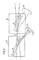
- the energy control mechanism 4 is illustrated with reference to Figure 2 in which the UV beam is focussed to a minimum width at location 19 after passing through an inclined plate 20.
- This plate may be orientated at various angles with respect to the incident energy by a moving coil mechanism shown partly as rectangle 21.
- the percentage of light reflected by plate 20 and thus deflected from location 19 is determined by the angle of incidence of the plate.
- the amount of energy transmitted to the second plate or shutter 22 may to a good approximation be made independent of the variations in pulse energy arriving at plate 20. Typically these variations are due to a variation in the period between requested pulses in energy.
- the transmission of plate 20 may be varied easily from 80% to 50% for an angle of deflection of less than 15 degrees and an average angle of incidence of 70 degrees.
- the laser source may provide energy pulses on a regular basis even when the system does not require one. This ensures steady state stability and minimises the risk of gross energy fluctuations.
- shutter 22 which operates as follows. In normal use the plate is positioned as shown by the solid line. The two end faces are transmitting. The moving coil actuator shown as a rectangle 24 can place the plate in the alternative position shown by the dashed line. Face 25 of plate 22 is coated to reflect the entire beam into energy dump 26. Thus pulses may be triggered internally by the -laser control system but are then deflected into dump 26 and, whilst keeping the system primed, do not register an exposure.
- the beam dissector shown in Figure I as element 8 is illustrated schematically in figure 3, in which it is assumed that the envelope of the UV beam has an aspect ratio of approximately four to one prior to entering the dissector.
- Four elemental square areas A, B, C and D are shown.
- a pair of parallel mirrors 27 and 28 displace the paths of rays from elements A and B vertically, whilst mirrors 29 and 30 displace the rays from C and D horizontally by twice this amount.
- the parallel mirror pairs may suitably be replaced by internally reflecting rhomboids.
- the aspect ratio of the input beam shown as four adjacent square elements A, B, C and D is four to one and that the divergence of the beam is at least four times greater in the long than in the short direction.
- each element is rotated through 90 degrees by two mirrors and rearranged in sequence.
- element A is rotated by mirrors 31 and 32 whilst B is rotated by mirrors 33 and 34 and so on.
- the net result is a composite beam with an envelope having an aspect ratio of four to one but this time the large divergence is in the narrow dimension.
- Two cylindrical lenses may now be used to eonverge this beam onto the end of a fibre 35 a small section of which is shown.
- the focal lengths of the two cylinders may be chosen to form an image on the fibre having approximately equal width and height.
- lens 37 caters for the higher divergence with a shorter focal length but need only handle a narrower beam.
- a beam dissector of this general design may be used to combine the outputs of two lasers into one composite beam, each laser beam --conveniently entering the dissector at different positions and, if desirable, from different directions.
- An important aspect of this invention is the use - of a single optical fibre or other light guide, such as a liquid light guide, as the means for transmitting the energy following reshaping by the beam dissector.
- the key requirement is that the energy distribution at the aperture 13 in figure I should be uniform over the full aperture.
- the optical fibre has very good characteristics for achieving this uniformity. No matter what the spatial distribution of light entering the fibre, this is completely scrambled to uniformly fill the output section on exiting the fibre.
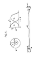
- the central axis 39 represents the optical axis of the fibre
- circle A represents one element converging onto axis 39
- element B is closer to the axis and also converging onto it.
- the dashed circle shown as the boundary of 38 represents the ex- scribed circle and, thus,the effective output cone exiting from the fibre. Allowing for the greater spreading of A on a larger circle than B (A being further off axis with respect to the fibre than B) the peak energy of A must be greater than B. Following rotational spreading the intensity contributions as a function of angle from the optical axis are shown in detail 40. Element B contributes the inner curve I B whilst element A contributes the curve [A.
- The-variable-T transmission plate 20 shown in Figure 2 will accommodate predictable variations.
- the photosensor 15 shown in Figure 1 is arranged to monitor system performance. Under a further refinement of the invention a photo detector may be used to provide a quantitative correction to the exposure provided. This is illustrated with reference to Figure 6 in which UV radiation causes a reverse biased photodiode 43 to develop a voltage across resistor 44. Amplifier 45 acts as a current source and, to first approximation, the current i o causes a charge to be stored by the capacitor 46 which is directly proportional to the number of photons which have arrived at photocell 43.
- the voltage V E on capacitor 46 is a direct representation of the exposure at the surface being exposed and is buffered by amplifier 47.
- a circuit shown schematically as rectangle 48 performs a comparison function, so that, when the required number of photons has arrived at cell 43 an output is generated on line 49 which causes the FET 50 to discharge the capacitor 46.
- the required number of photons may be selected by setting a threshold voltage V T .
- the output of diode 43 may also be used via line 51 by circuit 48, as a validation of the performance of the laser source and/or as a trigger signal.
- the remaining outputs 52from circuit 48 provide the system with status and control information. At its simplest level the system is not allowed to move to the next area to be exposed until the required exposure has been achieved. In systems where the laser energy reaching the area to be exposed may be varied under system control, a signal representing the additional exposure may be provided and used to control the transmission of energy to the exposing station at the next laser pulse.
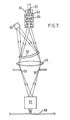
- a well polished fibre end 53 provides a spatially uniform disc of light and each point of this disc radiates in a forward cone.
- a small UV transparent window 61 may, optionally, be bonded with a UV transmitting cement to the fibre end 53. This provides two advantages. First, it prevents unwanted particles from contaminating the uniformly radiating disc and, second, it can be antireflection coated on face 62 to improve the overall transmission of the fibre subsystem.
- a small lens assembly 54 comprising three components to minimise spherical aberration, forms, in combination with a condenser lens 55, a magnified uniform image of fibre end 53 at the plane of aperture 56 (equivalent to aperture 13 in Figure 1).
- condenser lens 55 forms an image of the distribution of light exiting lens assembly 54 at the final imaging lens assembly 57, (equivalent to assembly 12 in Figure 1).
- the position of fibre end 53 may be adjusted relative to lens assembly 54 to achieve a result intermediate between that of Figure 1, in which the fibre end is imaged onto the pupil of assembly 57 and the point at which it is imaged onto aperture 56.
- magnification of lens assembly 54 may be so chosen as to provide a circle of illumination, having a diameter just in excess of the aperture's maximum diagonal, thus utilising the available energy most efficiently.
- a a low intensity off-axis image of the light exiting assembly 54 is provided by the uncoated face of an angled curved reflector 59, which passes the majority of light incident upon it to condenser 55. The reflected light is monitored by detector assembly 60.
- a further embodiment of the invention uses two laser sources.
- this invention allows more than one source of radiant energy to be combined to provide a uniform exposure at the exposing station.
- a nitrogen laser, or any similar laser such as one of a variety of excimer laser sources, is used
- extremely short pulses of energy typically of duration of 20 nanoseconds or less, arrive at the medium to be exposed, such as photoresist.
- a doubly pulsed single source may be-used or, conveniently, the outputs of two lasers may be combined with the introduction of a small delay between them..
- This delay may be selected to provide an overall short duration (eg 1 microsecond) comparable to or less than the duration of a conventional flash exposure, typically of the order of 10 microseconds and in any event, less than I millisecond, and long enough to provide optimum exposure at levels of energy well in excess of a conventional flash source.
- an overall short duration eg 1 microsecond
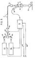
- FIG. 8 A block schematic layout of a two laser system is shown in Figure 8.
- the outputs from two lasers 63 and 64 are combined by auxiliary mirrors 65 and 66 through a beam dissector 67 into a composite beam 68.
- Beam 68 passes via a controllable attenuation device 69 and a focussing lens assembly 70 into a fibre 71.
- the output from fibre 71 substantially illuminates a controllable aperture 72 via lens assembly 73 and condenser lens 74.
- Aperture 72 is imaged onto the photoresist 75 by process lens assembly 76.
- a small proportion of the energy leaving lens assembly 73 is deflected by curved transmitting component 77 onto a photodetector 78, the output of which is fed to exposure control circuit 79.
- This circuit substantially in the form illustrated with reference to Figure 6, fires both lasers in addition to controlling the transmission of the optical train by affecting the position or state of an attenuating or blocking component in device 69.
- This may be an electro-mechanical device or one employing electro-optic principles.
- An input 80 to circuit 79 commences the process and an output 81 provides a handshake signal to the system controlling the overall pattern generation process.
Landscapes
- Physics & Mathematics (AREA)
- Optics & Photonics (AREA)
- General Physics & Mathematics (AREA)
- Engineering & Computer Science (AREA)
- Multimedia (AREA)
- Signal Processing (AREA)
- Plasma & Fusion (AREA)
- Mechanical Engineering (AREA)
- Theoretical Computer Science (AREA)
- Exposure And Positioning Against Photoresist Photosensitive Materials (AREA)
- Exposure Of Semiconductors, Excluding Electron Or Ion Beam Exposure (AREA)
Applications Claiming Priority (4)
| Application Number | Priority Date | Filing Date | Title |
|---|---|---|---|
| GB858511662A GB8511662D0 (en) | 1985-05-08 | 1985-05-08 | Providing uniform exposure |
| GB8511662 | 1985-05-08 | ||
| GB8527070 | 1985-11-04 | ||
| GB858527070A GB8527070D0 (en) | 1985-05-08 | 1985-11-04 | Providing uniform exposure |
Publications (2)
| Publication Number | Publication Date |
|---|---|
| EP0201306A2 true EP0201306A2 (fr) | 1986-12-17 |
| EP0201306A3 EP0201306A3 (fr) | 1989-06-28 |
Family
ID=26289228
Family Applications (1)
| Application Number | Title | Priority Date | Filing Date |
|---|---|---|---|
| EP86303396A Withdrawn EP0201306A3 (fr) | 1985-05-08 | 1986-05-06 | Appareil pour fournir une exposition uniforme à une station d'exposition |
Country Status (1)
| Country | Link |
|---|---|
| EP (1) | EP0201306A3 (fr) |
Cited By (12)
| Publication number | Priority date | Publication date | Assignee | Title |
|---|---|---|---|---|
| EP0452838A1 (fr) * | 1990-04-20 | 1991-10-23 | Hughes Aircraft Company | Dispositif de conjugaison de phase optique avec guide de lumière pour combinaison de plusieurs rayons lumineux |
| EP0479355A1 (fr) * | 1990-09-17 | 1992-04-08 | Koninklijke Philips Electronics N.V. | Dispositif et procédé pour former par un rayonnement électromagnétique des marques sur un objet et objet pourvu de marques |
| FR2675595A1 (fr) * | 1991-04-19 | 1992-10-23 | Sextant Avionique | Melangeur optique sans perturbations de chemins optiques notamment pour visuel de casque. |
| EP0485148A3 (en) * | 1990-11-07 | 1992-10-28 | Canon Kabushiki Kaisha | Image forming apparatus using light beam |
| EP0511058A1 (fr) * | 1991-04-25 | 1992-10-28 | Sextant Avionique | Mélangeur optique pour visuel de casque |
| EP0492844A3 (en) * | 1990-12-19 | 1993-01-13 | Hitachi, Ltd. | Method and apparatus for forming a light beam |
| GB2286900A (en) * | 1994-02-22 | 1995-08-30 | Mitsubishi Electric Corp | Laser optical transmission system and radiating method |
| GB2316187A (en) * | 1994-02-22 | 1998-02-18 | Mitsubishi Electric Corp | Laser optical fibre transmission system with adjustable angle of incidence |
| GB2329036A (en) * | 1997-09-05 | 1999-03-10 | Sharp Kk | Optical system for redistributing optical extent and illumination source |
| US6155688A (en) * | 1997-09-05 | 2000-12-05 | Sharp Kabushiki Kaisha | Dark field projection display |
| EP1498213A1 (fr) * | 2003-07-18 | 2005-01-19 | TRUMPF Laser GmbH + Co. KG | Appareil d'usinage par laser avec modulateur de puissance du laser |
| WO2009012913A1 (fr) * | 2007-07-21 | 2009-01-29 | Keming Du | Dispositif optique destiné à la production de faisceaux multiples |
Family Cites Families (4)
| Publication number | Priority date | Publication date | Assignee | Title |
|---|---|---|---|---|
| JPS58159514A (ja) * | 1982-03-18 | 1983-09-21 | Toshiba Corp | レ−ザビ−ム空間分布形成方法 |
| US4560856A (en) * | 1982-09-01 | 1985-12-24 | Westinghouse Electric Corp. | Pulsed laser machining apparatus |
| JPS5994704A (ja) * | 1982-11-20 | 1984-05-31 | Sumitomo Electric Ind Ltd | 露光量制御回路 |
| JPS59195891A (ja) * | 1983-04-20 | 1984-11-07 | Matsushita Electric Ind Co Ltd | 光フアイバ−を用いたレ−ザ−装置 |
-
1986
- 1986-05-06 EP EP86303396A patent/EP0201306A3/fr not_active Withdrawn
Cited By (23)
| Publication number | Priority date | Publication date | Assignee | Title |
|---|---|---|---|---|
| EP0452838A1 (fr) * | 1990-04-20 | 1991-10-23 | Hughes Aircraft Company | Dispositif de conjugaison de phase optique avec guide de lumière pour combinaison de plusieurs rayons lumineux |
| TR25976A (tr) * | 1990-04-20 | 1993-11-01 | Hughes Aircraft Co | Coklu demet bilesimi icin isik borusu iceren optik faz esleniklestirme aygiti |
| US5406042A (en) * | 1990-09-17 | 1995-04-11 | U.S. Philips Corporation | Device for and method of providing marks on an object by means of electromagnetic radiation |
| EP0479355A1 (fr) * | 1990-09-17 | 1992-04-08 | Koninklijke Philips Electronics N.V. | Dispositif et procédé pour former par un rayonnement électromagnétique des marques sur un objet et objet pourvu de marques |
| EP0485148A3 (en) * | 1990-11-07 | 1992-10-28 | Canon Kabushiki Kaisha | Image forming apparatus using light beam |
| US5398052A (en) * | 1990-11-07 | 1995-03-14 | Canon Kabushiki Kaisha | Image forming apparatus using overlapping light beams |
| US5973785A (en) * | 1990-12-19 | 1999-10-26 | Hitachi, Ltd. | Method of forming light beam, apparatus therefor, method of measuring sizes using the same, method of inspecting appearance, method of measuring height, method of exposure, and method of fabricating semiconductor integrated circuits |
| EP0492844A3 (en) * | 1990-12-19 | 1993-01-13 | Hitachi, Ltd. | Method and apparatus for forming a light beam |
| US5502001A (en) * | 1990-12-19 | 1996-03-26 | Hitachi, Ltd. | Method of forming light beam and method of fabricating semiconductor integrated circuits |
| FR2675595A1 (fr) * | 1991-04-19 | 1992-10-23 | Sextant Avionique | Melangeur optique sans perturbations de chemins optiques notamment pour visuel de casque. |
| EP0511889A1 (fr) * | 1991-04-19 | 1992-11-04 | Sextant Avionique | Mélangeur optique sans perturbations de chemins optiques, notamment pour visuel de casque |
| US5260829A (en) * | 1991-04-19 | 1993-11-09 | Sextant Avionique | Optical mixer without disturbance of optical paths, notably for helmet visual display system |
| FR2675911A1 (fr) * | 1991-04-25 | 1992-10-30 | Sextant Avionique | Melangeur optique pour visuel de casque. |
| US5243450A (en) * | 1991-04-25 | 1993-09-07 | Sextant Avionique | Optical mixer for helmet visual display system |
| EP0511058A1 (fr) * | 1991-04-25 | 1992-10-28 | Sextant Avionique | Mélangeur optique pour visuel de casque |
| GB2286900A (en) * | 1994-02-22 | 1995-08-30 | Mitsubishi Electric Corp | Laser optical transmission system and radiating method |
| GB2316187A (en) * | 1994-02-22 | 1998-02-18 | Mitsubishi Electric Corp | Laser optical fibre transmission system with adjustable angle of incidence |
| GB2316187B (en) * | 1994-02-22 | 1998-08-26 | Mitsubishi Electric Corp | Laser optical transmission system and radiating method |
| GB2286900B (en) * | 1994-02-22 | 1998-08-26 | Mitsubishi Electric Corp | Laser optical transmission system and radiating method |
| GB2329036A (en) * | 1997-09-05 | 1999-03-10 | Sharp Kk | Optical system for redistributing optical extent and illumination source |
| US6155688A (en) * | 1997-09-05 | 2000-12-05 | Sharp Kabushiki Kaisha | Dark field projection display |
| EP1498213A1 (fr) * | 2003-07-18 | 2005-01-19 | TRUMPF Laser GmbH + Co. KG | Appareil d'usinage par laser avec modulateur de puissance du laser |
| WO2009012913A1 (fr) * | 2007-07-21 | 2009-01-29 | Keming Du | Dispositif optique destiné à la production de faisceaux multiples |
Also Published As
| Publication number | Publication date |
|---|---|
| EP0201306A3 (fr) | 1989-06-28 |
Similar Documents
| Publication | Publication Date | Title |
|---|---|---|
| EP0201306A2 (fr) | Appareil pour fournir une exposition uniforme à une station d'exposition | |
| EP0493365B1 (fr) | Homogénisateur de faisceaux laser et système de prise de vue lidar avec cet homogénisateur | |
| KR100842426B1 (ko) | 조명이 가변 세팅되는 조명 시스템 | |
| DE60213187T2 (de) | Strahlungsquelle hoher Luminosität für die EUV-Lithographie | |
| US7109435B2 (en) | Beam irradiator and laser anneal device | |
| US10437072B2 (en) | Line beam forming device | |
| EP0097250A2 (fr) | Source lumineuse | |
| KR100259969B1 (ko) | 전필드마스크 조사 강화방법 및 장치 | |
| US20020041444A1 (en) | Device for converting the intensity distribution of a laser beam and a device and method for generating a laser beam with an intensity which falls constantly along an axis from one side of the beam to the other | |
| US20070272669A1 (en) | Laser Multiplexing | |
| US10743397B2 (en) | Method and device for generating electromagnetic radiation by means of a laser-produced plasma | |
| WO2021029969A1 (fr) | Conditionnement optique de plan focal pour photonique intégrée | |
| US10606096B2 (en) | Reducing an optical power of a reflected light beam | |
| US6624431B1 (en) | High collection angle short wavelength radiation collimator and focusing optic | |
| HK1008732B (en) | Full field mask illumination enhancement methods and apparatus | |
| US20160091647A1 (en) | Light Guide Based Optical System For Laser Line Generator | |
| JP2004266281A (ja) | レーザ光を物体に照射するための装置、物体を加工するための加工装置および画像情報を印刷するための印刷装置 | |
| US4132955A (en) | System for amplifying laser beams | |
| CN110574244B (zh) | 泵浦激光辐射的均匀化 | |
| JP2003218054A (ja) | レーザビーム長尺化装置 | |
| US10477664B1 (en) | Method and device for generating electromagnetic radiation by means of a laser-produced plasma | |
| TWI536122B (zh) | 微影投影曝光設備之照明系統 | |
| JP3406946B2 (ja) | 照明光学系およびこれを用いた光学装置ならびにその光学装置を用いたデバイス製造方法 | |
| Lopez-Urrutia et al. | Traveling-wave excitation of an x-ray laser medium | |
| US20260046995A1 (en) | Euv light source having a combination device |
Legal Events
| Date | Code | Title | Description |
|---|---|---|---|
| PUAI | Public reference made under article 153(3) epc to a published international application that has entered the european phase |
Free format text: ORIGINAL CODE: 0009012 |
|
| AK | Designated contracting states |
Kind code of ref document: A2 Designated state(s): AT BE CH DE FR GB IT LI LU NL SE |
|
| PUAB | Information related to the publication of an a document modified or deleted |
Free format text: ORIGINAL CODE: 0009199EPPU |
|
| RA1 | Application published (corrected) |
Date of ref document: 19861217 Kind code of ref document: A2 |
|
| RBV | Designated contracting states (corrected) |
Designated state(s): DE FR GB IT NL SE |
|
| PUAL | Search report despatched |
Free format text: ORIGINAL CODE: 0009013 |
|
| AK | Designated contracting states |
Kind code of ref document: A3 Designated state(s): DE FR GB IT NL SE |
|
| STAA | Information on the status of an ep patent application or granted ep patent |
Free format text: STATUS: THE APPLICATION IS DEEMED TO BE WITHDRAWN |
|
| 18D | Application deemed to be withdrawn |
Effective date: 19891203 |
|
| RIN1 | Information on inventor provided before grant (corrected) |
Inventor name: ANDERSON, JOHN DOUGLAS Inventor name: STREET, GRAHAM STEWART BRANDON Inventor name: DASHWOOD, NIGEL JOHN ROBERT |