EP0201309A2 - Véhicule aérien - Google Patents
Véhicule aérien Download PDFInfo
- Publication number
- EP0201309A2 EP0201309A2 EP86303415A EP86303415A EP0201309A2 EP 0201309 A2 EP0201309 A2 EP 0201309A2 EP 86303415 A EP86303415 A EP 86303415A EP 86303415 A EP86303415 A EP 86303415A EP 0201309 A2 EP0201309 A2 EP 0201309A2
- Authority
- EP
- European Patent Office
- Prior art keywords
- vehicle
- envelope
- air
- passageway
- duct
- Prior art date
- Legal status (The legal status is an assumption and is not a legal conclusion. Google has not performed a legal analysis and makes no representation as to the accuracy of the status listed.)
- Withdrawn
Links
- 230000000694 effects Effects 0.000 claims description 10
- 230000033001 locomotion Effects 0.000 claims description 10
- 238000013016 damping Methods 0.000 claims description 9
- 239000000725 suspension Substances 0.000 claims description 4
- 239000013598 vector Substances 0.000 claims description 4
- 239000007788 liquid Substances 0.000 claims description 3
- 238000005086 pumping Methods 0.000 claims 1
- 239000007789 gas Substances 0.000 abstract description 15
- 239000001307 helium Substances 0.000 abstract description 8
- 229910052734 helium Inorganic materials 0.000 abstract description 8
- SWQJXJOGLNCZEY-UHFFFAOYSA-N helium atom Chemical compound [He] SWQJXJOGLNCZEY-UHFFFAOYSA-N 0.000 abstract description 8
- 241000239290 Araneae Species 0.000 description 8
- 239000000463 material Substances 0.000 description 8
- 230000002441 reversible effect Effects 0.000 description 7
- 230000006872 improvement Effects 0.000 description 4
- 230000007423 decrease Effects 0.000 description 3
- 239000000853 adhesive Substances 0.000 description 2
- 230000001070 adhesive effect Effects 0.000 description 2
- 230000008859 change Effects 0.000 description 2
- 238000013461 design Methods 0.000 description 2
- 238000010438 heat treatment Methods 0.000 description 2
- 239000011159 matrix material Substances 0.000 description 2
- XLYOFNOQVPJJNP-UHFFFAOYSA-N water Substances O XLYOFNOQVPJJNP-UHFFFAOYSA-N 0.000 description 2
- 229920002799 BoPET Polymers 0.000 description 1
- 229920000049 Carbon (fiber) Polymers 0.000 description 1
- 229920004934 Dacron® Polymers 0.000 description 1
- JOYRKODLDBILNP-UHFFFAOYSA-N Ethyl urethane Chemical compound CCOC(N)=O JOYRKODLDBILNP-UHFFFAOYSA-N 0.000 description 1
- 240000002836 Ipomoea tricolor Species 0.000 description 1
- 229920000271 Kevlar® Polymers 0.000 description 1
- 239000005041 Mylar™ Substances 0.000 description 1
- 235000014443 Pyrus communis Nutrition 0.000 description 1
- RTAQQCXQSZGOHL-UHFFFAOYSA-N Titanium Chemical compound [Ti] RTAQQCXQSZGOHL-UHFFFAOYSA-N 0.000 description 1
- 239000000654 additive Substances 0.000 description 1
- XAGFODPZIPBFFR-UHFFFAOYSA-N aluminium Chemical compound [Al] XAGFODPZIPBFFR-UHFFFAOYSA-N 0.000 description 1
- 229910052782 aluminium Inorganic materials 0.000 description 1
- 238000004873 anchoring Methods 0.000 description 1
- 239000004760 aramid Substances 0.000 description 1
- 229920006231 aramid fiber Polymers 0.000 description 1
- 230000005540 biological transmission Effects 0.000 description 1
- 239000004917 carbon fiber Substances 0.000 description 1
- 235000019506 cigar Nutrition 0.000 description 1
- 238000010276 construction Methods 0.000 description 1
- 230000008878 coupling Effects 0.000 description 1
- 238000010168 coupling process Methods 0.000 description 1
- 238000005859 coupling reaction Methods 0.000 description 1
- 230000005611 electricity Effects 0.000 description 1
- 239000003822 epoxy resin Substances 0.000 description 1
- 238000002474 experimental method Methods 0.000 description 1
- 239000000835 fiber Substances 0.000 description 1
- 230000008014 freezing Effects 0.000 description 1
- 238000007710 freezing Methods 0.000 description 1
- 239000002828 fuel tank Substances 0.000 description 1
- 239000003502 gasoline Substances 0.000 description 1
- 239000003365 glass fiber Substances 0.000 description 1
- 238000010348 incorporation Methods 0.000 description 1
- 239000004761 kevlar Substances 0.000 description 1
- 238000012986 modification Methods 0.000 description 1
- 230000004048 modification Effects 0.000 description 1
- 230000002093 peripheral effect Effects 0.000 description 1
- 229920000647 polyepoxide Polymers 0.000 description 1
- 239000005020 polyethylene terephthalate Substances 0.000 description 1
- 238000012545 processing Methods 0.000 description 1
- 230000004044 response Effects 0.000 description 1
- 230000000717 retained effect Effects 0.000 description 1
- 230000035939 shock Effects 0.000 description 1
- 229910052719 titanium Inorganic materials 0.000 description 1
- 239000010936 titanium Substances 0.000 description 1
Images


Classifications
-
- B—PERFORMING OPERATIONS; TRANSPORTING
- B64—AIRCRAFT; AVIATION; COSMONAUTICS
- B64B—LIGHTER-THAN AIR AIRCRAFT
- B64B1/00—Lighter-than-air aircraft
-
- B—PERFORMING OPERATIONS; TRANSPORTING
- B64—AIRCRAFT; AVIATION; COSMONAUTICS
- B64B—LIGHTER-THAN AIR AIRCRAFT
- B64B1/00—Lighter-than-air aircraft
- B64B1/02—Non-rigid airships
-
- B—PERFORMING OPERATIONS; TRANSPORTING
- B64—AIRCRAFT; AVIATION; COSMONAUTICS
- B64B—LIGHTER-THAN AIR AIRCRAFT
- B64B1/00—Lighter-than-air aircraft
- B64B1/06—Rigid airships; Semi-rigid airships
- B64B1/24—Arrangement of propulsion plant
- B64B1/30—Arrangement of propellers
- B64B1/34—Arrangement of propellers of lifting propellers
-
- B—PERFORMING OPERATIONS; TRANSPORTING
- B64—AIRCRAFT; AVIATION; COSMONAUTICS
- B64U—UNMANNED AERIAL VEHICLES [UAV]; EQUIPMENT THEREFOR
- B64U30/00—Means for producing lift; Empennages; Arrangements thereof
- B64U30/20—Rotors; Rotor supports
- B64U30/26—Ducted or shrouded rotors
-
- B—PERFORMING OPERATIONS; TRANSPORTING
- B64—AIRCRAFT; AVIATION; COSMONAUTICS
- B64U—UNMANNED AERIAL VEHICLES [UAV]; EQUIPMENT THEREFOR
- B64U50/00—Propulsion; Power supply
- B64U50/10—Propulsion
- B64U50/12—Propulsion using turbine engines, e.g. turbojets or turbofans
-
- B—PERFORMING OPERATIONS; TRANSPORTING
- B64—AIRCRAFT; AVIATION; COSMONAUTICS
- B64U—UNMANNED AERIAL VEHICLES [UAV]; EQUIPMENT THEREFOR
- B64U50/00—Propulsion; Power supply
- B64U50/10—Propulsion
- B64U50/18—Thrust vectoring
Definitions
- This invention relates generally to vehicles for lifting and transporting loads by air.
- a vehicle of this type will hereinafter be referred to as an "air vehicle”.
- Eshoo U.S. Patent No. 4,326,681 discloses an example of a non-rigid air ship which relies for lift on both heated air and on a gas which is lighter than air.
- Batchelor U.S. Patent No. 3,658,278 discloses a load transporting system in which a balloon supports a flexible electric line leading from a source of electricity to a load carrying device including a helium filled rotor and means for releasing gas to provide a load carrying force.
- An object of the present invention is to provide an air vehicle suitable for use in commercial load carrying operations.
- the vehicle provided by the invention includes an envelope having the general shape of a torus extending about a passageway between top and bottom surfaces of the envelope.
- the envelope contains a gas, preferably a lighter than air gas.
- Fan means is carried by the envelope and is arranged to direct air downwardly through the passageway to generate a downwardly vectored thrust for lifting the vehicle.
- the fan means is controllable to vary the magnitude of the thrust and hence the altitude of the vehicle in flight.
- the envelope also carries propulsion means for generally lateral propulsion of the vehicle.
- the vehicle provided by the invention derives lift both from the lighter than air gas within the envelope and from the thrust provided by the fan means. It is believed that this provision for lift from two sources will permit the design of a vehicle which is not only capable of lifting relatively heavy loads but in which the altitude of the vehicle can be easily and precisely controlled in use. It is also believed that it will be possible to build and operate such a vehicle quite economically.
- the vehicle may be designed so that the gas within the envelope provides sufficient lift to support the weight of the vehicle when unloaded.
- the fan means need then generate only sufficient thrust to be capable of lifting the load to the required altitude.
- the gas could provide positive buoyancy for the unloaded vehicle although this may then require the addition of means for tethering or anchoring the vehicle when unloaded.
- the gas within the envelope is preferably, but not essentially, a lighter than air gas such as helium; for example, air could be used in the envelope. In this event means may be provded for heating the air to provide lift.
- the vehicle includes means for controlling the direction of the thrust vector provided by the fan means, to control the attitude of the vehicle.
- a further embodiment provides means for generating additional lift by the so-called "wing effect" of air flowing over the top surface of the envelope into the passageway through the envelope.
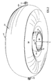
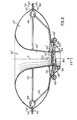
- an air vehicle is generally denoted by reference numeral 20 and includes an envelope 22 having the general shape of a torus.
- a passageway generally denoted 24 extends between top and bottom surfaces 26 and 28 respectively of the envelope.
- the envelope contains a gas which is lighter than air (in practice, helium)'.
- Fan means shown in Figs. 1 and 3 and denoted generally 30 are carried by the envelope and arranged to direct air downwardly through passageway 24 to generate a downwardly vectored thrust for lifting the envelope.
- two fans 32 and 34 are provided and are driven individually by respective jet engines 36 and 38.
- the engines can be controlled to vary the magnitude of the thrust and hence the height of the vehicle in flight, in known manner.'
- the vehicle is provided with a pair of propulsion units in the form of jet engines 42 and 44 which are carried by the envelope and arranged for propelling the vehicle generally laterally.
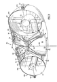
- the envelope 22 comprises essentially a non-rigid gas-impervious bag 46 having the general shape of a torus; the bag is normally maintained in an inflated condition by helium gas under pressure.
- Bag 46 is made of a polymeric material, in this embodiment the material sold under the trade mark MYLAR.
- a saddle the shape. of which can perhaps best be seen in Fig. 1 extends across the top of the bag and provides a support for the fans 30 and 32 and the engines by which they are driven.
- the saddle is generally indicated by reference numeral 48 and includes an elongate center portion 48a which extends generally diamentrally of the torus and by which the fans 32, 34 and the engines 36, 38 are supported.
- Continuations 48b of the center portion 48a extend part way down the sides of the-bag and carry the engines 42 and 44.
- the engines are disposed generally on a median plane through the torus.
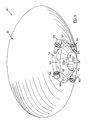
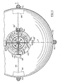
- the saddle also includes an annular portion 48c which overlies the top of the bag 46 and in effect defines the top surface of the torus. As can best be seen in Fig. 3, this annular portion 48c also extends partially down the inside surface of the torus defining the opening 24 to the edge denoted 48d in Fig. 3.
- a second annular member denoted 50 Adjacent the bottom of passageway 24 is a second annular member denoted 50 which is also of an arcuate shape in cross-section conforming generally to the curvature of bag 46.
- the bag is secured by adhesive to the bottom member 50 and to the saddle 48 so that the member and saddle partially support the bag in its inflated condition.
- Saddle 48 and member 50 are bonded structures typically formed from an epoxy resin matrix and aramid fibers such as those sold under the trade mark KEVLAR. Glass and/or carbon fibers may also be incorporated. Other alternative materials are aluminum and titanium.
- An air bag 52 is provided inside the torus 22 and comprises a closed tubular structure disposed generally on the center line of the torus and maintained in position by supporting wires indicated at 54. Bag 52 contains air and can be inflated or deflated to control the buoyancy of the envelope, as is conventional in air ships. When the air bag 52 is inflated the density of the helium within the bag 46 is increased, reducing its buoyancy. Conversely, deflation of air bag 52 allows the density of the helium to decrease, increasing its buoyancy.
- a suitable air pump, power source and control equipment will of course be provided in the vehicle for inflating and deflating the air bag 52. This equipment will be carried from the saddle 48 of the vehicle but, for simplicity, has not been shown since it forms no part of the present invention and is similar to equipment conventionally used in air ships.
- each of the lift fans 32, 34 is supported on saddle 48 above an associated duct, 56, 58 extending downwardly from the saddle.
- the two ducts 56, 58 merge at a circular chamber 60 generally at the center of the torus 22.
- Chamber 60 contains two stacked, contra-rotating, free-wheeling fans 62, 64 rotatable about the center line of chamber 60. These fans are designed to turn in opposite directions under the influence of air from the fans 32, 34 and serve to mix the air into a uniform, downwardly directed stream. That stream enters a discharge duct within a somewhat conically shaped duct member 66, in the center of which is suspended a bell-shaped duct member 68.
- the two members define therebetween a narrow duct 70 which is generally of hollow conical shape and which defines an annular air outlet nozzle 72 at the bottom of the torus. Accordingly, air leaves nozzle 72 in an annular stream or curtain around the perimeter of the bell member 68.
- a universal joint 74 carried at the lower end of a shaft about which the two fans 62 and 64 rotate.
- the universal joint 74 allows the bell member 68 to be deflected laterally with respect to the outer member 66 to vary the shape of nozzle 72 and hence the configuration of the curtain of air issuing from the nozzle.
- the attitude of the vehicle can be controlled in flight. This is accomplished by three actuators mutually spaced at 120° about the perimeter of nozzle 72. Two of those actuators are visible in Fig. 3 and are denoted by reference numeral 76. Referring to the actuator which is seen at the right in Fig.
- each actuator is carried by the outer duct member 66 and includes an operating member 78 which extends inwardly and is coupled to the bell member at its outer end.
- Each actuator comprises a fast acting stepping motor operated by suitable control equipment (not shown) carried by the saddle 48 of the vehicle.
- suitable control equipment not shown
- the actuator 76 could be replaced by other forms of actuator, for example, hydraulic cylinders.
- the duct assembly comprising the ducts 56, 58, chamber 60 and the members 66 and 70 may all be formed as bonded structures from the same materials as the saddle 48 and bottom member 50.
- Guy wires 79 stabilize the duct assembly with respect to the saddle 48 and bottom member 50.
- the two jet engines 36 and 38 are located within respective housings 80 and 82 at the underside of the center portion 48a of saddle 48 and have suitable vents 84 and 86.
- the engines themselves are essentially conventional aircraft-type jet engines connected through suitable gearboxes to respective drive shafts 88 and 90 coupled to the associated fans 32 and 34 respectively.
- Suitable. angle drives 92 and 94 connect the drive shafts to the fan axles.
- the universal joint 74 at the apex of the bell member 68 is also used as an attachment point for suspending loads from the vehicle.
- an attenuator 96 is suspended from the universal joint 74 and extends downwardly from the vehicle as indicated by line 98 for attachment of loads below the vehicle.
- Attentuator 96 takes the form of a hydraulic cylinder and performs a shock absorbing function in the suspension line.
- the attentuator will be quite short and a cable or other suspension element will extend downwardly from the attentuator for actually carrying the load.
- the two engines 42 and 44 for propelling the vehicle laterally through the air are also essentially conventional jet engines and are positioned at diametrally opposite sides of the torus for use in maneuvering the vehicle.
- the engines are reversible.
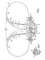
- the vehicle shown in Figs. 4 to 6 has the same principal components as the vehicle shown in the previous views, namely a torus-shaped envelope 22' defining a central passageway 24', fan means 30', and propulsion means, in this case represented by four generally laterally directed jet engines individually denoted 100.
- the torus-shaped envelope 22' is generally similar to the envelope 22 of the previous views although of somewhat different cross-sectional shape, and that the saddle 48 of the previous embodiment has been omitted.
- the torus itself may be of the same construction as in the previous embodiments and may have an internal air bag as bag 52 if required.
- the fan means 30' in the embodiment of Fig. 6 is positioned at the bottom of the passageway and draws air downwardly through the passageway.
- a member 102 having the general shape of an inverted cone with a concave profile and a flat base.
- the member is arranged so that its base is disposed generally in the same plane as the top surface of the torus for minimzing drag as the vehicle moves through the air.
- the member is located by guy wires 104 extending between it and the envelope 22' and is positioned with its concave surfaces spaced from the opposing surfaces of the envelope 22' so that the shape of passageway 24' is in effect defined between the envelope and the member 102.
- the passageway has an annular shape, the diameter of which gradually increases towards the top of the torus, where the passageway flares outwardly and merges smoothly with the top surface of the envelope.
- Member 102 is arranged so that the width of the annulus decreases somewhat towards the top surface of the torus generally in the regions indicated by arrows 106 in Fig. 6, to achieve a venturi effect causing the velocity of the air entering the passageway 24' to be accelerated.
- the air being drawn into the passageway by the fan means 30' is drawn over the convex profile generally denoted 108 at the top of the torus and is accelerated, creating a low pressure area above surface 108 which tends to augment the lifting forces being imposed on the envelope. In other words, a "wing" effect is created, increasing the lifting forces acting on the vehicle.
- Means may be provided for tilting member 102 to change the shape of passageway 24', to control the stability and/or pitch of the vehicle. These means may be essentially similar to the actuators used for duct member 68 in the preceding embodiment.
- member 102 may be omitted.
- the fan means 30' of the vehicle is supported by a "gondola" structure 110 which is in turn carried at the lower end of a member. 112 of inverted conical shape disposed within the passageway 24' through the envelope 22'.
- the upper end of the cone is of greater diameter than the minimum diameter of passageway 24' when the envelope 22' is fully inflated so.that the member tends to be held in the passageway by the envelope.
- the envelope is also secured to the member by adhesive.
- the envelope extends to the lower edge of member 112 and accordingly has the general shape of a pear drop in this embodiment. This arrangement has been found to distribute stresses uniformly and directly to the envelope surface and avoids the need for guy wires secured to load patches on the envelope, as is conventional in the art.
- the envelope could, in itself, be an incomplete torus shape and attached to the upper end of member 112 and the outer extremity of the gondola, for example at the points denoted A and B in Fig. 6. Member 112 and the gondola would then have to be designed to, in effect, complete the torus. It is believed that this configuration would offer advantages in terms of lowering the maximum stress on the envelope because the stress would then be exerted over a larger diameter area.
- Gondola 110 has a central opening 114 which has substantially the same diameter as the lower end of member 112.
- the fan means 30' takes the form of a fan 116 disposed with its axis of rotation coincident with the axis of member 112 and passageway 114.
- Fan 116 is supported by a "spider" structure 120 that forms part of an internal “space frame” of the gondola.
- This frame is designed on conventional airframe design principles and, therefore, has not been shown in detail.
- the frame merely provides support for the various components of the gondola, and for the pilots.
- Spider structure 120 has four arms 122 disposed generally mutually at right angles and extending outwardly through the gondola 110 from the center of opening 114. The structure is held in place by virtue of the fact that the arms 122 extend through the walls of the gondola as shown at the lefthand side of the gondola in Fig. 6.
- the gondola is shown partly sectioned in that view about a section line 124; the portion of the drawing to the right of the section line shows the external appearance of the gondola including part of one of the propulsion units 100 while the portion of the drawing to the left of the center line shows the gondola structure in section.
- This latter portion of the view clearly indicates the fact that the gondola includes an inner wall 110a which defines the opening 114, and an outer wall 110b which extends upwardly and outwardly from the lower end of the inner wall 110a.
- the arms 122 of spider structure 120 extend through openings in both of those walls. If necessary, the arms may be retained by suitable retaining means (not shown).
- the space between the two walls 110a and 110b of the gondola may be used to house control equipment, fuel tanks, power supplies, etc., or even for carrying passengers in larger vehicles.
- windows have been shown at 125 but, of course, need not necessarily be present.
- the gondola structure and member 112 are made as bonded matrix/fiber structures as discussed previously in connection with the preceding embodiment.
- Each of the propulsion units 100 is mounted at the outer end of one of the spider structure arms 122.
- Fig. 7 is a vertical sectional view through a typical one of those propulsion units.
- the unit includes a housing 126 surrounding a reversible electric motor 128 supported by struts 130 from the housing 126.
- the motor has a drive shaft which projects from both ends of the motor housing and the shaft is fitted at each end with a propellor.
- the two propellors are denoted respectively 132 and 134 in Fig. 7 and are positioned at 90° with respect to one another.
- the blades of the propellors are designed to produce equal thrust in whichever direction the motor turns.
- Reversible electric motors may not be suitable for large size vehicles.
- Alternatives are gas or jet engines with reversible transmission systems or arrangements using two engines.
- Another possibility would be to use a ducted air system (vectored thrust).
- a still further possibility is to use a non-reversible motor or engine with a variable pitch propeller capable of being controlled to provide thrust selectively in forward or reverse directions.
- Fig. 4 shows the relative orientations of the four propulsion units 100. It will be seen that the units are spaced mutually at 90° from one another about the vertical center line of the vehicle and are oriented so that the thrust vector of each unit is generally tangential to a notional circle drawn on that center line and passing through all four units. It has been found that this orientation of propulsion units coupled with the feature of reversibility discussed above allows for substantial maneuverability of the vehicle in flight. In an alternative embodiment, three propulsion units equally spaced around the gondola could be used.
- a vehicle of the form described above derives lift forces both from the gas within the torus shaped envelope of the vehicle and from the lift fan or fans which provide readily controllable vectored thrust for varying the altitude of the vehicle. Independent control of all directions of lateral movement (including left, right and yaw) is also provided.
- the embodiment of Figs. 5 to 7 provides additional lift by virtue of the "wing effect" of air flowing over the top surface of the torus.
- a vehicle in accordance with the invention may be constructed with an envelope diameter of 140 feet and an envelope height of 55 feet, an operating altitude of 4,000 feet and a maximum forward air speed of 40 m.p.h. These dimensions of course given by way of example only and may vary in practice.
- the vehicle could also be built to a relatively small scale for use as a toy.
- Figs. 8 to 12 in describing a further embodiment of the invention.
- the air vehicle shown in these views is generally similar to the vehicle shown in Figs. 4 to 7 but incorporates additional improvements.
- Double primed reference numerals are used in Figs. 8 to 12 to denote parts corresponding with parts shown in previous views.
- the vehicle has an envelope 22" attached to a rigid cone member 112" from which is suspended a gondola 110".
- a spider structure 120" carried by the gondola has four radial arms 122" that project outwardly from the gondola and carry propulsion units 100" at their outer ends.
- a vertical lift fan 116" is carried by the spider structure 120" for directing air downwardly through a central passageway 24" through the torus shaped envelope.
- the principal components of the vehicle thus far described are essentially similar to the preceding embodiment and are made of similar materials.
- the envelope 22" incorporates an internal hoop 140 that defines the maximum diameter of the torus.
- the envelope is attached to hoop 140 at spaced positions around the hoop by conventional attachment means (not shown).
- Hoop 140 is dimensioned with respect to the envelope 22" to define a leading edge or "nose” in the cross-sectional shape of the torus as generally indicated at 142 in Fig. 9. As seen in Fig. 8, this leading edge of course extends around the entire periphery of the envelope.
- the envelope has a cross-sectional shape resembling a flattened ellipse which is somewhat pointed at the leading edge 142. This shape streamlines the envelope for lateral movement of the vehicle through the air, reducing drag. Some lift may also be generated due to air flow over the convex surface above the leading edge 142.
- the overall sape of the envelope may be termed a "torroidal ellipsoid".
- Hoop 140 additionally serves to permit attachment of other components to the envelope.
- These include four vertical thrusters two of which are visible in Fig. 9 and are individually denoted 144. As can best been seen in Fig. 8, there are in fact four such thrusters 144 equally spaced around the perimeter of the vehicle.
- the arrow denoted F in Fig. 8 indicates the direction of forward motion of the vehicle.
- One of the thrusters 144 is disposed at the forward end of the vehicle with respect to this intended direction of movement while the other three thrusters are equally spaced at the rear and two opposite sides.
- the lateral propulsion units 100" are correspondingly positioned; accordingly, the four arms 122' of the spider structure 120 t by which these units are carried are disposed at right angles to one another on what might be termed as a "fore-and-aft" axis and a "lateral" axis of the craft as best seen in Fig. 11.
- the two axes are denoted respectively as “X” and "Y”.
- a vertical axis at right angles to axes "X” and "Y” on the centerline of the vehicle would be denoted "z" (see Fig. 9).
- inclinometers Two of the arms 122" that are disposed mutually at right angles incorporate devices known as "inclinometers". Inclinometers are conventional level sensing devices and are available from Sperry Corporation. Other conventional angle detecting means (such as gyroscopes) could alternatively be used. In any event, in Fig. 11, the two inclinometers are denoted by reference numeral 146 and one of those inclinometers is also visible in Fig. 9. Each inclinometer responds to changes in the inclination of the arm 122' by which it is carried. The particular inclinometers used in this embodiment provide outputs in terms of millivolts per degree of inclination. Those outputs are electronically processed by conventional means and used to control the thrusters 144 externally of the envelope. The particular inclinometers used have a very fast response (are extremely sensitive) so that the thrusters 144 respond almost instantaneously to signals from the inclinometers.
- Each inclinometer 146 in effect senses the inclination of the vehicle along the particular axis "X” or “Y” on which the inclinometer is disposed.
- the inclinometer on axis "X” controls the thrusters 144 at the front and rear of the craft while the other inclinometer controls the lateral thrusters.
- the signals from the inclinometers are processed so that the thrusters tend to maintain the craft in a stable attitude along both axes.
- the thrusters 144 and the inclinometers 146 and associated signal processing equipment combine to provide what is referred to as a "damping system" for the vehicle in the sense that the thrusters 144 will resist forces tending to cause the vehicle to swing about the "X" or "Y" axis.
- a "damping system” for the vehicle in the sense that the thrusters 144 will resist forces tending to cause the vehicle to swing about the "X" or "Y" axis.
- the thrust generated by the propulsion units 100 is below the center of drag of the vehicle and causes the vehicle to tend to incline upwardly at its leading end to some extent.
- the damping system then maintains that stable attitude and does not attempt to force the vehicle back to a horizontal attitude. This occurs because the damping system is designed to respond to changes in inclination of the craft rather than to absolute deviation from the horizontal.
- the damping thrusters could be used to control the pitch of the vehicle (about axis "Y").
- each of the thrusters 144 comprises a fan 148 that is rotatable about a vertical axis and driven by an electric motor 150.
- the motor is supported by a strut 152 that extends outwardly from the envelope and is connected through the envelope to the hoop 140.
- a housing 154 also extends outwardly from the hoop and around the fan.
- damping thrusters need not be positioned on axes extending fore and aft and from side to side of the vehicle.
- the thrusters could be 45 0 offset from those axes.
- more than four or as few as three damping thrusters could be used.
- FIG. 10 is an enlarged view of the gondola 110" of the vehicle and shows this single drive motor at 156.
- drive motor 156 may take the form of a gasoline engine running at constant speed.
- Motor 156 is mounted within the gondola 110" at the rear side thereof as contrasted with the direction of forward motion indicated at F in Fig. 10.
- a cockpit will provided for one or more pilots at the front of the vehicle, generally in the area denoted 158 to counterbalance the weight of the drive motor 156.
- Drive motor 156 has an output shaft 160 that extends radially inwardly through the inner wall of the gondola to a gearbox 162 disposed on the vertical centerline C of the vehicle below the fan 116".
- Gearbox 162 has-five output shafts. Four shafts -extend laterally from the gearbox through the respective arms 122" of the spider structure to the lateral propulsion units 100". Three of those shafts are visible in Fig. 10 and are individually denoted by reference 164. At their outer ends, the shafts 164 drive' the propulsion units 110 through suitable conventional rightangle drive couplings.
- the fifth output shaft of gearbox 162 is not specifically shown but extends vertically upwardly from gearbox 162 and carries the fan 116".
- Suitable conventional servomotor controls will be provided for the fan 116" and each of the propulsion unit propellors to permit pitch changes in accordance with the thrust required to be generated by the particular fan or propellor. These controls have not been illustrated. since they are conventional. Provision will also of course be made to change the normal constant speed of the drive motor 156 to accomodate extraordinary thrust requirements.
- a trim control system As best shown in Fig. 12, the system essentially comprises two ballast tanks 166 and 168 disposed respectively at the front and rear of the vehicle and connected by piping 170 incorporating a pump 172. Pump 172 is operated to pump liquid between the two tanks in accordance with trim requirements. Any suitable liquid can be used in the trim control system, preferably water with suitable additives if necessary to lower the freezing point of the water.
- Figs. 9 and 11 show the trim control system as installed in the vehicle.
- the two tanks 166 and 168 are disposed within envelope 22" and are coupled to the hoop 140.
- the piping 170 is routed through the envelope and around the vertical air passageway 24", where the pump 172 is located.
- Pump 172 will of course be integrated into the overall control system for the vehicle so that it can be remotely operated either by the pilots in the case of a manned vehicle or from the ground where remote control is used.
- the vehicle shown in Figs. 8 to 12 incorporates several improvements as compared with the preceding embodiment, namely the improved torus shape, the damping system for maintaining a stable attitude, a single drive motor for vehicle thrust and lateral propulsion, and a trim control system.
- An important practical feature of the vehicle common to all embodiments is that the vehicle does not rely on aerodynamic control surfaces to maintain stability or attitude. In other words, there is no need for the vehicle to have forward velocity to have control.
- the vehicle In both of the embodiments described with reference to Figs. 4 to 12, the vehicle is inherently stable because the center of mass is below the center of lift. The vehicle also provides for independent control of motion in the directions of the "X", “Y” and “Z” axes as well as turning motion about the "Z" axis (yaw). In the embodiment of Figs. 8 to 12, the damping thrusters prevent turning about the "X" and "Y" axes.
- the envelope of the vehicle is formed of a urethane impregnated DACRON (TM) material conventionally used in airships, although there is of course no limitation to this particular material; within the broad scope of the invention, the envelope could even be rigid.
- TM urethane impregnated DACRON
- the engines and motors used in the vehicle need not be of the types specifically described above.
- the engines 36 and 38 in the first embodiment need not be jet engines.
- the gondola (in the embodiments of Figs. 4 to 12) need not be of annular form.
- An elongate gondola e.g. "cigar shaped" may be preferred for smaller craft where minimum drag is important.
- a vertical passageway may be provided through this type of gondola also, for accommodating a vertical lift thruster.
- torus as used herein is to be interpreted broadly.
- the term includes shapes such as those shown in Fig. 6 and those which result in a section through the torus having an elliptical or flattened elliptical shape. In the latter case the torus would have a shape similar to that of a "flying saucer".
- the torus shape shown in Figs. 8 and 9 (the "leading edge” shape) could be achieved other than by means of a hoop within envelope 22"; for example, cables or webs could be used to hold the envelope in the required shape.
- the shape need not be circular in plan and could, overall, resemble a conventional airship shape but with a vertical passageway for the lift thruster.
- the envelope may in fact have any shape (not necessarily torroidal).
- an envelope having the shape of a delta wing could be employed.
Landscapes
- Engineering & Computer Science (AREA)
- Chemical & Material Sciences (AREA)
- Combustion & Propulsion (AREA)
- Aviation & Aerospace Engineering (AREA)
- Mechanical Engineering (AREA)
- Structures Of Non-Positive Displacement Pumps (AREA)
- Toys (AREA)
- Vehicle Cleaning, Maintenance, Repair, Refitting, And Outriggers (AREA)
Applications Claiming Priority (4)
| Application Number | Priority Date | Filing Date | Title |
|---|---|---|---|
| CA480837 | 1985-05-06 | ||
| CA480837 | 1985-05-06 | ||
| CA507803 | 1986-04-28 | ||
| CA507803 | 1986-04-28 |
Publications (2)
| Publication Number | Publication Date |
|---|---|
| EP0201309A2 true EP0201309A2 (fr) | 1986-11-12 |
| EP0201309A3 EP0201309A3 (fr) | 1987-05-27 |
Family
ID=25670678
Family Applications (1)
| Application Number | Title | Priority Date | Filing Date |
|---|---|---|---|
| EP86303415A Withdrawn EP0201309A3 (fr) | 1985-05-06 | 1986-05-06 | Véhicule aérien |
Country Status (3)
| Country | Link |
|---|---|
| EP (1) | EP0201309A3 (fr) |
| KR (1) | KR860008916A (fr) |
| AU (1) | AU588312B2 (fr) |
Cited By (20)
| Publication number | Priority date | Publication date | Assignee | Title |
|---|---|---|---|---|
| US5026003A (en) * | 1989-08-28 | 1991-06-25 | Smith William R | Lighter-than-air aircraft |
| RU2127693C1 (ru) * | 1997-09-11 | 1999-03-20 | Хорьков Николай Федорович | Многофункциональный высокоманевренный летательный аппарат вертикального взлета и посадки |
| WO2000032469A1 (fr) * | 1998-12-01 | 2000-06-08 | Fazakas Gabor | Dirigeable toroidal hybride |
| GB2362145A (en) * | 2000-05-08 | 2001-11-14 | Marin Dimitrov Guenov | Re-usable space vehicle launch system using air-buoyant craft |
| DE10023269A1 (de) * | 2000-05-12 | 2001-11-29 | Josef Sykora | Luftfahrzeug |
| GB2366274A (en) * | 2000-08-31 | 2002-03-06 | Edmund Peter Gortowski | A compact, economic and manoeuverable aircraft |
| FR2831518A1 (fr) * | 2001-10-30 | 2003-05-02 | Voliris | Aeronef de type dirigeable a sustentation auxiliaire |
| FR2851224A1 (fr) * | 2003-02-18 | 2004-08-20 | Andre Dejoux | Aeronefs hybrides, comportant un systeme d'allegement torique et une voilure tournante centrale |
| WO2004074091A3 (fr) * | 2003-02-24 | 2004-11-25 | Charles Raymond Luffman | Aeronef |
| WO2007034193A3 (fr) * | 2005-09-22 | 2007-06-07 | Kit Nicholson | Generateur de puissance a voiles |
| RU2396185C1 (ru) * | 2008-10-31 | 2010-08-10 | Олег Васильевич Черёмушкин | Летательный аппарат черёмушкина о.в. |
| EP1896321A4 (fr) * | 2005-06-23 | 2011-08-03 | Marine 1 Llc | Applications associees a un systeme de commande d'un vaisseau marin |
| US8167236B2 (en) | 2006-08-29 | 2012-05-01 | Shell Technology Ventures Fund 1.B.V. | Hybrid lift air vehicle |
| WO2015000088A1 (fr) * | 2013-07-04 | 2015-01-08 | Marco Tausel | Support structural gonflable pour systèmes de commande et de propulsion d'uav (aéronef téléguidé) |
| US9274528B2 (en) | 2005-06-23 | 2016-03-01 | Marine 1, Llc | Marine vessel control system |
| WO2016124761A1 (fr) * | 2015-02-06 | 2016-08-11 | Universite Technologie De Compiegne - Utc | Robot aérien et procédé de catapultage d'un robot aérien |
| US9975633B1 (en) | 2016-05-10 | 2018-05-22 | Northrop Grumman Systems Corporation | Collapsible ducted fan unmanned aerial system |
| US10267949B2 (en) | 2014-10-17 | 2019-04-23 | Sony Corporation | Information processing apparatus and information processing method |
| CN113788136A (zh) * | 2021-11-10 | 2021-12-14 | 中国空气动力研究与发展中心低速空气动力研究所 | 一种中轴通气聚光飞艇 |
| CN119239938A (zh) * | 2024-10-23 | 2025-01-03 | 华北科技学院(中国煤矿安全技术培训中心) | 一种设置风激励升力设备的应急救援高空舱 |
Families Citing this family (1)
| Publication number | Priority date | Publication date | Assignee | Title |
|---|---|---|---|---|
| KR20000053970A (ko) * | 2000-05-15 | 2000-09-05 | 김진경 | 가벼운 기체의 부력에 의한 무선조종 비행체 |
Family Cites Families (4)
| Publication number | Priority date | Publication date | Assignee | Title |
|---|---|---|---|---|
| FR2286754A1 (fr) * | 1974-10-03 | 1976-04-30 | Onera (Off Nat Aerospatiale) | Engin aerostat, notamment pour le transport et/ou la manutention de tres lourdes charges |
| US4114837A (en) * | 1977-03-24 | 1978-09-19 | Skagit Corporation | Air transport and lifting vehicle |
| US4269375A (en) * | 1979-10-31 | 1981-05-26 | Hickey John J | Hybrid annular airship |
| FR2539383A1 (fr) * | 1983-01-19 | 1984-07-20 | Nguyen Tan Chuonv | Aeronef torique allege telecommande pour la teledetection aerienne |
-
1986
- 1986-05-05 AU AU57105/86A patent/AU588312B2/en not_active Ceased
- 1986-05-06 KR KR1019860003507A patent/KR860008916A/ko not_active Withdrawn
- 1986-05-06 EP EP86303415A patent/EP0201309A3/fr not_active Withdrawn
Cited By (22)
| Publication number | Priority date | Publication date | Assignee | Title |
|---|---|---|---|---|
| US5026003A (en) * | 1989-08-28 | 1991-06-25 | Smith William R | Lighter-than-air aircraft |
| RU2127693C1 (ru) * | 1997-09-11 | 1999-03-20 | Хорьков Николай Федорович | Многофункциональный высокоманевренный летательный аппарат вертикального взлета и посадки |
| WO2000032469A1 (fr) * | 1998-12-01 | 2000-06-08 | Fazakas Gabor | Dirigeable toroidal hybride |
| GB2362145A (en) * | 2000-05-08 | 2001-11-14 | Marin Dimitrov Guenov | Re-usable space vehicle launch system using air-buoyant craft |
| DE10023269A1 (de) * | 2000-05-12 | 2001-11-29 | Josef Sykora | Luftfahrzeug |
| GB2366274A (en) * | 2000-08-31 | 2002-03-06 | Edmund Peter Gortowski | A compact, economic and manoeuverable aircraft |
| FR2831518A1 (fr) * | 2001-10-30 | 2003-05-02 | Voliris | Aeronef de type dirigeable a sustentation auxiliaire |
| FR2851224A1 (fr) * | 2003-02-18 | 2004-08-20 | Andre Dejoux | Aeronefs hybrides, comportant un systeme d'allegement torique et une voilure tournante centrale |
| WO2004074091A3 (fr) * | 2003-02-24 | 2004-11-25 | Charles Raymond Luffman | Aeronef |
| US9274528B2 (en) | 2005-06-23 | 2016-03-01 | Marine 1, Llc | Marine vessel control system |
| EP1896321A4 (fr) * | 2005-06-23 | 2011-08-03 | Marine 1 Llc | Applications associees a un systeme de commande d'un vaisseau marin |
| WO2007034193A3 (fr) * | 2005-09-22 | 2007-06-07 | Kit Nicholson | Generateur de puissance a voiles |
| US8167236B2 (en) | 2006-08-29 | 2012-05-01 | Shell Technology Ventures Fund 1.B.V. | Hybrid lift air vehicle |
| RU2396185C1 (ru) * | 2008-10-31 | 2010-08-10 | Олег Васильевич Черёмушкин | Летательный аппарат черёмушкина о.в. |
| WO2015000088A1 (fr) * | 2013-07-04 | 2015-01-08 | Marco Tausel | Support structural gonflable pour systèmes de commande et de propulsion d'uav (aéronef téléguidé) |
| US10267949B2 (en) | 2014-10-17 | 2019-04-23 | Sony Corporation | Information processing apparatus and information processing method |
| WO2016124761A1 (fr) * | 2015-02-06 | 2016-08-11 | Universite Technologie De Compiegne - Utc | Robot aérien et procédé de catapultage d'un robot aérien |
| FR3032425A1 (fr) * | 2015-02-06 | 2016-08-12 | Univ Tech De Compiegne - Utc | Robot aerien et procede de catapultage d'un robot aerien |
| US9975633B1 (en) | 2016-05-10 | 2018-05-22 | Northrop Grumman Systems Corporation | Collapsible ducted fan unmanned aerial system |
| CN113788136A (zh) * | 2021-11-10 | 2021-12-14 | 中国空气动力研究与发展中心低速空气动力研究所 | 一种中轴通气聚光飞艇 |
| CN113788136B (zh) * | 2021-11-10 | 2022-04-22 | 中国空气动力研究与发展中心低速空气动力研究所 | 一种中轴通气聚光飞艇 |
| CN119239938A (zh) * | 2024-10-23 | 2025-01-03 | 华北科技学院(中国煤矿安全技术培训中心) | 一种设置风激励升力设备的应急救援高空舱 |
Also Published As
| Publication number | Publication date |
|---|---|
| EP0201309A3 (fr) | 1987-05-27 |
| AU588312B2 (en) | 1989-09-14 |
| KR860008916A (ko) | 1986-12-19 |
| AU5710586A (en) | 1986-11-13 |
Similar Documents
| Publication | Publication Date | Title |
|---|---|---|
| US4685640A (en) | Air vehicle | |
| EP0201309A2 (fr) | Véhicule aérien | |
| US4366936A (en) | Aircraft having buoyant gas balloon | |
| US4601444A (en) | Aerial load-lifting system | |
| US4695012A (en) | Aerial load-lifting system | |
| US3976265A (en) | Semibuoyant composite aircraft | |
| RU2196703C2 (ru) | Летательный аппарат с фюзеляжем, выполненным по существу в виде аэростатического подъемного тела, двигательная установка и способ управления летательным аппаратом | |
| US5295643A (en) | Unmanned vertical take-off and landing, horizontal cruise, air vehicle | |
| JP3468783B2 (ja) | 全方向推進型飛行船 | |
| CN100423991C (zh) | 一种飞行器及空中运输的方法与运输载荷的系统 | |
| US3054578A (en) | Annular aircraft with elastic collector ring rim | |
| US3350035A (en) | Vtol with cylindrical wing | |
| US6142414A (en) | Rotor--aerostat composite aircraft | |
| US4114837A (en) | Air transport and lifting vehicle | |
| JPH11513635A (ja) | ハイブリッド航空機 | |
| EP0135501A1 (fr) | Structure volante | |
| JPH08509930A (ja) | ダクト付きカウンタ回転同軸ロータを有する無人飛行体の空力的補助構造体 | |
| PT1551706E (pt) | Dirigível de casco duplo controlado por orientação do impulso | |
| US6082478A (en) | Lift augmented ground effect platform | |
| US4365772A (en) | Aircraft having buoyant gas balloon | |
| US3856236A (en) | Composite aircraft | |
| US5070955A (en) | Passively stable hovering system | |
| US11628955B2 (en) | Aerial system utilizing a tethered uni-rotor network of satellite vehicles | |
| GB2387158A (en) | Aerial flying device | |
| EP0023843B1 (fr) | Aéronef à ballon de gaz de flottabilité |
Legal Events
| Date | Code | Title | Description |
|---|---|---|---|
| PUAI | Public reference made under article 153(3) epc to a published international application that has entered the european phase |
Free format text: ORIGINAL CODE: 0009012 |
|
| AK | Designated contracting states |
Kind code of ref document: A2 Designated state(s): AT BE CH DE FR GB IT LI LU NL SE |
|
| PUAL | Search report despatched |
Free format text: ORIGINAL CODE: 0009013 |
|
| AK | Designated contracting states |
Kind code of ref document: A3 Designated state(s): AT BE CH DE FR GB IT LI LU NL SE |
|
| 17P | Request for examination filed |
Effective date: 19871119 |
|
| 17Q | First examination report despatched |
Effective date: 19880727 |
|
| STAA | Information on the status of an ep patent application or granted ep patent |
Free format text: STATUS: THE APPLICATION IS DEEMED TO BE WITHDRAWN |
|
| 18D | Application deemed to be withdrawn |
Effective date: 19900810 |
|
| RIN1 | Information on inventor provided before grant (corrected) |
Inventor name: KRAMER, DALE CLIFFORD Inventor name: WARRINGTON, JOHN EDWARD Inventor name: NINKOVICH, GEORGE |