EP0201314A2 - Fork and arm mechanism for refuse container - Google Patents
Fork and arm mechanism for refuse container Download PDFInfo
- Publication number
- EP0201314A2 EP0201314A2 EP86303429A EP86303429A EP0201314A2 EP 0201314 A2 EP0201314 A2 EP 0201314A2 EP 86303429 A EP86303429 A EP 86303429A EP 86303429 A EP86303429 A EP 86303429A EP 0201314 A2 EP0201314 A2 EP 0201314A2
- Authority
- EP
- European Patent Office
- Prior art keywords
- refuse
- housing member
- fluid
- chamber
- retainer
- Prior art date
- Legal status (The legal status is an assumption and is not a legal conclusion. Google has not performed a legal analysis and makes no representation as to the accuracy of the status listed.)
- Withdrawn
Links
- 239000012530 fluid Substances 0.000 claims abstract description 56
- 238000007599 discharging Methods 0.000 claims 2
- 230000004888 barrier function Effects 0.000 claims 1
Images


Classifications
-
- B—PERFORMING OPERATIONS; TRANSPORTING
- B65—CONVEYING; PACKING; STORING; HANDLING THIN OR FILAMENTARY MATERIAL
- B65F—GATHERING OR REMOVAL OF DOMESTIC OR LIKE REFUSE
- B65F3/00—Vehicles particularly adapted for collecting refuse
- B65F3/02—Vehicles particularly adapted for collecting refuse with means for discharging refuse receptacles thereinto
- B65F3/04—Linkages, pivoted arms, or pivoted carriers for raising and subsequently tipping receptacles
-
- B—PERFORMING OPERATIONS; TRANSPORTING
- B60—VEHICLES IN GENERAL
- B60G—VEHICLE SUSPENSION ARRANGEMENTS
- B60G2204/00—Indexing codes related to suspensions per se or to auxiliary parts
- B60G2204/40—Auxiliary suspension parts; Adjustment of suspensions
- B60G2204/47—Means for retracting the suspension
-
- B—PERFORMING OPERATIONS; TRANSPORTING
- B60—VEHICLES IN GENERAL
- B60G—VEHICLE SUSPENSION ARRANGEMENTS
- B60G2300/00—Indexing codes relating to the type of vehicle
- B60G2300/03—Silo or fluid transporting vehicles
-
- B—PERFORMING OPERATIONS; TRANSPORTING
- B60—VEHICLES IN GENERAL
- B60G—VEHICLE SUSPENSION ARRANGEMENTS
- B60G2300/00—Indexing codes relating to the type of vehicle
- B60G2300/40—Variable track or wheelbase vehicles
-
- B—PERFORMING OPERATIONS; TRANSPORTING
- B60—VEHICLES IN GENERAL
- B60G—VEHICLE SUSPENSION ARRANGEMENTS
- B60G2300/00—Indexing codes relating to the type of vehicle
- B60G2300/40—Variable track or wheelbase vehicles
- B60G2300/402—Extra load carrying wheels, e.g. tag axles
-
- B—PERFORMING OPERATIONS; TRANSPORTING
- B60—VEHICLES IN GENERAL
- B60G—VEHICLE SUSPENSION ARRANGEMENTS
- B60G2400/00—Indexing codes relating to detected, measured or calculated conditions or factors
- B60G2400/60—Load
- B60G2400/61—Load distribution
-
- B—PERFORMING OPERATIONS; TRANSPORTING
- B65—CONVEYING; PACKING; STORING; HANDLING THIN OR FILAMENTARY MATERIAL
- B65F—GATHERING OR REMOVAL OF DOMESTIC OR LIKE REFUSE
- B65F3/00—Vehicles particularly adapted for collecting refuse
- B65F3/02—Vehicles particularly adapted for collecting refuse with means for discharging refuse receptacles thereinto
- B65F2003/0263—Constructional features relating to discharging means
- B65F2003/0279—Constructional features relating to discharging means the discharging means mounted at the front of the vehicle
Definitions
- Certain types of refuse containers have an opening in the upper portion thereof through which refuse is dumped into the container.
- Some of such refuse containers have in combination therewith an arm and fork unit which is operable to lift a refuse retainer and to move the refuse retainer to a position over the opening and to discharge the refuse from the retainer into the refuse container through the opening therein.
- Most of such refuse containers are carried by a vehicle for movement of the refuse container.
- arm and fork units have limited fork movement.
- the limited fork movement creates a problem.
- the forks cannot be moved to a horizontal position at the top surface of the container. Therefore, such forks extend upwardly from the upper surface of the container and create problems in the movement of a refuse container carrier vehicle along a highway which has limited height regulations.
- the arms and forks must be positioned at the front of the vehicle before travel occurs. Such a position of the arms and forks at the front of the vehicle partially obstructs and limits the visibility of an operator of the vehicle which carries the container.
- the forks can extend only forwardly of the vehicle which carries the refuse container.
- the forks in such units cannot be moved to a vertical position.
- the forwardly extending forks present hazard conditions.
- the forks can be positioned horizontally at the upper surface of the refuse container during travel of the refuse container.
- the forks can be moved to a position in juxtaposition with the arms at any position of the arms.
- the forks can be vertically oriented when the forks are positioned in front of a vehicle which carries the refuse container.
- An additional or alternative object is to provide such a fork and arm mechanism which is capable of rapid pivotal movement of the forks.
- This invention comprises a fork and arm mechanism for a refuse container.
- the invention also comprises motor means for operation of the forks in the fork and arm mechanism.
- the motor means comprises a reciprocally operable fluid motor which includes an elongate housing. Within the elongate housing are a plurality of axially aligned spaced-apart pistons, all of which are secured to a common piston rod. The piston rod extends from the housing. The housing is provided with a plurality of spaced-apart fluid ports. Fluid which flows into and out of the fluid ports is controlled so that fluid pressure is applied selectively to the pistons, and thus axial movement and positioning of the piston rod are controlled.
- the mechanism may include a pair of spaced-apart arms which are pivotally carried by the refuse container.
- a pivotal shaft extends between the arms.
- a pair of fluid motors is carried by the arms.
- the fluid motors are operably joined to the shaft which is carried by the arm members.
- a pair of forks is attached to the shaft.
- the fluid motors operate together to pivotally move the shaft and the forks.
- At any pivotal position of the arms the forks are pivotally movable through a relatively wide angle.
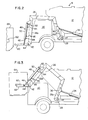
- FIG. 1 shows generally a vehicle 10 upon which is mounted a refuse container 12 which has an opening 16 in the upper portion thereof. The opening 16 is closeable by a door 18. A packer member 20 and a power unit 22 for operation of the packer member 20 are shown within the refuse container 12.
- An arm member 26 is mounted on each of the opposite sides of the refuse container 12. Each arm member 26 is pivotally attached by means of a pin 27 to a base 28 of the refuse container 12. Each of the arms 26 is shown as having a connection portion 26a and a carrier portion 26b. In FIGS. 1 and 2 the arms 26 are shown in a position extending over a cab 30 of the vehicle 10. The arms 26 are joined together and are pivotally moved by linearly operable fluid motors 34. Each fluid motor 34 is pivotally attached to the base 28 of the refuse container 12 and is also pivotally attached to a bracket 36 which is joined to the connection portion 26a of one of the arms 26.
- each arm 26 is shown positioned in front of the cab 30. Pivotally supported at the lower end of the carrier portion 26b of the arms 26 is a shaft 42 which extends between the arms 26. Attached to the shaft 42 adjacent each of the arms 26 is a bifurcated link 44. Pivotally attached to each bifurcated link 44 is an actuator rod 46 of a reciprocally operable fluid motor 48.
- the fluid motor 48 also has an elongate housing 50, the upper part of which is pivotally attached to a bracket 54 which is attached to the carrier portion 26b of the arm 26.
- Attached to the shaft 42 adjacent the arms 26 and the bifurcated links 44 are a pair of spaced-apart forks 60.
- the forks 60 pivotally move with pivotal movement of the shaft 42.
- the arms 26 are movable by the fluid motors 34 between the position of the arms 26 shown in FIGS. 1 and 2 and the position of the arms 26 shown in FIGS. 4 and 6.
- the forks 60 are substantially horizontal and are positioned to move into sleeves 62 of a refuse retainer 64.
- the vehicle 10 is driven forwardly.
- the arms 26 are pivotally moved to the position thereof shown in FIG. 3'.
- the refuse retainer 64 is moved to the position thereof shown in FIG. 3.
- the forks 60 are pivotally moved with respect to the arms 26. Therefore, when the arms 26 are positioned as shown in FIG. 3, the forks 60 are substantially horizontal and the refuse retainer remains horizontal.
- the forks 60 remain substantially at the same angle with respect to the arms 26, as shown in broken lines in FIG. 4.
- the forks 60 are pivotally moved to the position shown in solid lines in FIG. 4, and tilting and tipping of the refuse retainer 64 is completed for dumping the contents of the refuse retainer 64 into the refuse container 12.
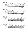
- FIGS. 8, 9, 10, and 11 illustrate one of the fluid motors 48 and the operating positions thereof.
- Each of the fluid motors 48 has an actuator rod 46 and a housing 50.
- Within the housing 50 are a plurality:of spaced-apart axially aligned pistons 70, 72, and 74, all of which are secured to the actuator rod 46.
- the housing 50 has a plurality of spaced-apart ports 82, 84, 86, and 88.
- a source of fluid is joined to each of the ports 82, 84, 86, and 88:
- fluid is introduced into the housing 50 through the ports 82 and 84, and fluid is exhausted from the housing 50 through the ports 88 and 86.
- This condition of the fluid motor 48 is illustrated in FIG. 9.
- FIG. 5 illustrates a position of the forks 60 when the forks 60 are in front of the cab 30 of the vehicle 10.
- the forks 60 are adjacent the arms 26 and substantially parallel thereto. Due to the fact that this position of the forks 60 is unobtrusive, this is an excellent position for the forks 60 when the vehicle 10 travels.
- the condition of the fluid motor 48 is as shown in FIG. 8. Fluid is introduced into the housing 50 through the ports 88 and 86 and fluid is exhausted from the housing 50 through the ports 82 and 84.
- FIG. 6 illustrates a position of the forks 60 when the forks are positioned above the refuse container 12.
- the forks are adjacent the upper surface of the refuse container 12 and substantially parallel thereto. This is an excellent position for the forks 60 during travel of the vehicle 10, due to the fact that the total height of the structure is a minimum.
- the arms 26 and the forks 60 do not obstruct the vision of the driver of the vehicle 10 during travel of the vehicle 10.
- fluid is forced into the housing 50 through the ports 86 and 88. Fluid is exhausted through the ports 82 and 84. This condition is illustrated in FIG. 8.
- the fork operator mechanism of this invention is capable of pivotal movement of the forks throughout a wide angle of operation.
- the mechanism is capable of positioning the forks in excellent positions for vehicle travel as well as for lifting and dumping of a refuse container.
- the mechanism is also capable of relatively rapid fork movement.
Landscapes
- Engineering & Computer Science (AREA)
- Mechanical Engineering (AREA)
- Forklifts And Lifting Vehicles (AREA)
- Refuse Collection And Transfer (AREA)
- Supplying Of Containers To The Packaging Station (AREA)
- Control And Other Processes For Unpacking Of Materials (AREA)
- Load-Engaging Elements For Cranes (AREA)
Abstract
Description
- Certain types of refuse containers have an opening in the upper portion thereof through which refuse is dumped into the container. Some of such refuse containers have in combination therewith an arm and fork unit which is operable to lift a refuse retainer and to move the refuse retainer to a position over the opening and to discharge the refuse from the retainer into the refuse container through the opening therein. Most of such refuse containers are carried by a vehicle for movement of the refuse container.
- Most of such arm and fork units have limited fork movement. The limited fork movement creates a problem. For example, when the arms are positioned above the refuse container, the forks cannot be moved to a horizontal position at the top surface of the container. Therefore, such forks extend upwardly from the upper surface of the container and create problems in the movement of a refuse container carrier vehicle along a highway which has limited height regulations. In such arm and fork units, the arms and forks must be positioned at the front of the vehicle before travel occurs. Such a position of the arms and forks at the front of the vehicle partially obstructs and limits the visibility of an operator of the vehicle which carries the container.
- Frequently for short distance travel of the vehicle which carries a refuse container it is desired to maintain the forks at the front of the vehicle during travel. However, in known arm and fork units, the forks can extend only forwardly of the vehicle which carries the refuse container. The forks in such units cannot be moved to a vertical position. The forwardly extending forks present hazard conditions.
- It is an object of this invention to provide a fork and arm mechanism for a refuse container in which the forks are pivotally movable throughout a relatively large angle. Thus, the forks can be positioned horizontally at the upper surface of the refuse container during travel of the refuse container. Also, the forks can be moved to a position in juxtaposition with the arms at any position of the arms. Thus, the forks can be vertically oriented when the forks are positioned in front of a vehicle which carries the refuse container.
- An additional or alternative object is to provide such a fork and arm mechanism which is capable of rapid pivotal movement of the forks.
- This invention comprises a fork and arm mechanism for a refuse container. The invention also comprises motor means for operation of the forks in the fork and arm mechanism.
- In one embodiment, the motor means comprises a reciprocally operable fluid motor which includes an elongate housing. Within the elongate housing are a plurality of axially aligned spaced-apart pistons, all of which are secured to a common piston rod. The piston rod extends from the housing. The housing is provided with a plurality of spaced-apart fluid ports. Fluid which flows into and out of the fluid ports is controlled so that fluid pressure is applied selectively to the pistons, and thus axial movement and positioning of the piston rod are controlled.
- The mechanism may include a pair of spaced-apart arms which are pivotally carried by the refuse container. A pivotal shaft extends between the arms. A pair of fluid motors is carried by the arms. The fluid motors are operably joined to the shaft which is carried by the arm members. A pair of forks is attached to the shaft. The fluid motors operate together to pivotally move the shaft and the forks. At any pivotal position of the arms the forks are pivotally movable through a relatively wide angle. By this means a refuse retainer is lifted by the forks and arms and moved to a position above the opening in the upper portion of the refuse container. The forks then are moved pivotally to tilt the refuse retainer to deposit the refuse from the refuse retainer into the refuse container through the opening in the refuse container.
- In order that the invention may be more readily understood, one embodiment thereof will now be described with reference to the accompanying drawings, in which:-
- FIG. 1 is a side elevational view with parts broken away and shown in section showing a refuse container and a vehicle which carries the refuse container. This view also illustrates one of the arm positions and illustrates the manner in which the arms and forks are positioned for lifting a refuse retainer for movement of the refuse retainer to a position above the refuse container for dumping the contents of the refuse retainer into the refuse container.
- FIG. 2 is a fragmentary side elevation view of an arm and fork unit of this invention and also shows the refuse container and supporting vehicle. FIG. 2 is drawn on a larger scale than FIG. 1. This view shows the same arm position as FIG. 1, and illustrates another angular position of the forks at this arm position.
- FIG. 3 is a fragmentary side elevational view, similar to FIG. 1, drawn on substantially the same scale as FIG. 2, illustrating another arm position during lifting and lowering of a refuse retainer and illustrating another angular position of the forks at this arm position.
- FIG. 4 is a fragmentary side elevational view, similar to FIGS. 2 and 3 illustrating another arm position. At this arm position dumping of a refuse retainer occurs. This view also illustrates angular fork positions at this arm position.
- FIG. 5 is a fragmentary side elevational view of the arm and fork unit, showing the arms positioned in the manner illustrated in FIG. 2, but showing the forks in another angular position.
- FIG. 6 is a fragmentary side elevational view of the arms and forks, showing the arms positioned in the manner illustrated in FIG. 4, but showing the forks in another angular position.
- FIG.-7 is a front elevational view showing the arm and fork unit.
- FIG. 8 is a diagrammatic side elevational view of a fluid operable motor of this invention and illustrating the piston and piston rod positions when the forks are in a predetermined position thereof with respect to the arms.
- FIG. 9 is a diagrammatic side elevational view, similar to FIG. 8, illustrating the piston and piston rod positions when the forks are in another position with respect to the arms.
- FIG. 10 is a diagrammatic side sectional view, similar to FIGS. 8 and 9, illustrating the piston and piston rod positions when the forks are in another position with respect to the arms.
- FIG. 11 is a diagrammatic side sectional view, similar to FIGS. 8, 9, and 10, illustrating the piston and piston rod positions when the forks are in another position with respect to the arms.
- FIG. 1 shows generally a
vehicle 10 upon which is mounted arefuse container 12 which has an opening 16 in the upper portion thereof. The opening 16 is closeable by adoor 18. Apacker member 20 and apower unit 22 for operation of thepacker member 20 are shown within therefuse container 12. - An
arm member 26 is mounted on each of the opposite sides of therefuse container 12. Eacharm member 26 is pivotally attached by means of apin 27 to abase 28 of therefuse container 12. Each of thearms 26 is shown as having aconnection portion 26a and acarrier portion 26b. In FIGS. 1 and 2 thearms 26 are shown in a position extending over acab 30 of thevehicle 10. Thearms 26 are joined together and are pivotally moved by linearlyoperable fluid motors 34. Eachfluid motor 34 is pivotally attached to thebase 28 of therefuse container 12 and is also pivotally attached to abracket 36 which is joined to theconnection portion 26a of one of thearms 26. - In FIGS. 1, 2, and 7 the
carrier portion 26b of eacharm 26 is shown positioned in front of thecab 30. Pivotally supported at the lower end of thecarrier portion 26b of thearms 26 is ashaft 42 which extends between thearms 26. Attached to theshaft 42 adjacent each of thearms 26 is a bifurcatedlink 44. Pivotally attached to each bifurcatedlink 44 is anactuator rod 46 of a reciprocallyoperable fluid motor 48. Thefluid motor 48 also has anelongate housing 50, the upper part of which is pivotally attached to a bracket 54 which is attached to thecarrier portion 26b of thearm 26. - Attached to the
shaft 42 adjacent thearms 26 and thebifurcated links 44 are a pair of spaced-apartforks 60. Theforks 60 pivotally move with pivotal movement of theshaft 42. - The
arms 26 are movable by thefluid motors 34 between the position of thearms 26 shown in FIGS. 1 and 2 and the position of thearms 26 shown in FIGS. 4 and 6. In the position of thearms 26 and theforks 60 as shown in FIG. 1, theforks 60 are substantially horizontal and are positioned to move intosleeves 62 of arefuse retainer 64. In order for theforks 60 to move into thesleeves 62 thevehicle 10 is driven forwardly. After theforks 60 are moved into thesleeves 62 of therefuse retainer 64 thearms 26 are pivotally moved to the position thereof shown in FIG. 3'. Thus, therefuse retainer 64 is moved to the position thereof shown in FIG. 3. During movement of thearms 26 from the position thereof shown in FIG. 1 to the position thereof shown in FIG. 3, theforks 60 are pivotally moved with respect to thearms 26. Therefore, when thearms 26 are positioned as shown in FIG. 3, theforks 60 are substantially horizontal and the refuse retainer remains horizontal. - Then the arms 26-are pivotally moved to the position thereof shown in FIG. 4. During the movement of the
arms 26 from the position shown in FIG. 3 to the position shown in FIG. 4, theforks 60 remain substantially at the same angle with respect to thearms 26, as shown in broken lines in FIG. 4. Thus, as thearms 26 reach the position thereof shown in FIG. 4, tilting and tipping of therefuse retainer 64 has begun. Then theforks 60 are pivotally moved to the position shown in solid lines in FIG. 4, and tilting and tipping of therefuse retainer 64 is completed for dumping the contents of therefuse retainer 64 into therefuse container 12. - Then the
arms 26 and theforks 60 are pivotally returned to the positions thereof shown in FIG. 3 and then to the positions thereof shown in FIG. 1. - FIGS. 8, 9, 10, and 11 illustrate one of the
fluid motors 48 and the operating positions thereof. Each of thefluid motors 48, as stated above and as shown, has anactuator rod 46 and ahousing 50. As shown in FIGS. 8, 9, 10, and 11, within thehousing 50 are a plurality:of spaced-apart axially alignedpistons actuator rod 46. Thehousing 50 has a plurality of spaced-apart ports ports - When it is desired to move the
forks 60 to the position thereof with respect to thearms 26, as shown in FIG. 1 fluid is introduced into thehousing 50 through theports port 86, and theport 88 is blocked against fluid flow. This condition of thefluid motor 48 is illustrated in FIG. 11. - To position the
forks 60 with respect to thearms 26 as shown in FIG. 3, fluid is introduced into thehousing 50 through theports housing 50 through theports fluid motor 48 is illustrated in FIG. 9. - When the
arms 26 are positioned as illustrated in FIG. 4, to position theforks 60 with respect to thearms 26 as shown in solid lines in FIG. 4, fluid is introduced into thehousing 50 through theports port 84.Port 82 is blocked against fluid flow. This condition of thefluid motor 48 is illustrated in FIG. 10. - FIG. 5 illustrates a position of the
forks 60 when theforks 60 are in front of thecab 30 of thevehicle 10. Theforks 60 are adjacent thearms 26 and substantially parallel thereto. Due to the fact that this position of theforks 60 is unobtrusive, this is an excellent position for theforks 60 when thevehicle 10 travels. When theforks 60 are so positioned, the condition of thefluid motor 48 is as shown in FIG. 8. Fluid is introduced into thehousing 50 through theports housing 50 through theports - FIG. 6 illustrates a position of the
forks 60 when the forks are positioned above therefuse container 12. The forks are adjacent the upper surface of therefuse container 12 and substantially parallel thereto. This is an excellent position for theforks 60 during travel of thevehicle 10, due to the fact that the total height of the structure is a minimum. Furthermore, in the positions of thearms 26 andforks 60 as shown in FIG. 6, thearms 26 and theforks 60 do not obstruct the vision of the driver of thevehicle 10 during travel of thevehicle 10. In order to pivotally position theforks 60 with respect to thearms 26 as illustrated in FIG. 6, fluid is forced into thehousing 50 through theports ports - Thus, it is understood that the fork operator mechanism of this invention is capable of pivotal movement of the forks throughout a wide angle of operation. The mechanism is capable of positioning the forks in excellent positions for vehicle travel as well as for lifting and dumping of a refuse container. The mechanism is also capable of relatively rapid fork movement.
- Although the preferred embodiment of the mechanism of this invention has been described, it will be understood that within the purview of this invention various changes may be made in the form, details, proportion and arrangement of parts, the combination thereof, and the mode of operation, which generally stated consist in fork mechanism for refuse container within the scope of the appended claims.
Claims (6)
Applications Claiming Priority (2)
| Application Number | Priority Date | Filing Date | Title |
|---|---|---|---|
| US731096 | 1985-05-06 | ||
| US06/731,096 US4647267A (en) | 1985-05-06 | 1985-05-06 | Fork and arm mechanism for refuse container |
Publications (2)
| Publication Number | Publication Date |
|---|---|
| EP0201314A2 true EP0201314A2 (en) | 1986-11-12 |
| EP0201314A3 EP0201314A3 (en) | 1988-07-06 |
Family
ID=24938047
Family Applications (1)
| Application Number | Title | Priority Date | Filing Date |
|---|---|---|---|
| EP86303429A Withdrawn EP0201314A3 (en) | 1985-05-06 | 1986-05-06 | Fork and arm mechanism for refuse container |
Country Status (7)
| Country | Link |
|---|---|
| US (1) | US4647267A (en) |
| EP (1) | EP0201314A3 (en) |
| AU (1) | AU577190B2 (en) |
| DK (1) | DK205686A (en) |
| FI (1) | FI861888L (en) |
| NO (1) | NO861782L (en) |
| NZ (1) | NZ216045A (en) |
Cited By (1)
| Publication number | Priority date | Publication date | Assignee | Title |
|---|---|---|---|---|
| EP0708038A1 (en) * | 1994-10-13 | 1996-04-24 | C.E.B. COSTRUZIONI ECOLOGICHE BERGOMI S.r.L. | Truck-associated device for gripping and automatically lifting refuse collection bins |
Families Citing this family (14)
| Publication number | Priority date | Publication date | Assignee | Title |
|---|---|---|---|---|
| US5193882A (en) * | 1991-10-01 | 1993-03-16 | Gamaldi Paul M | Mechanism for raising and tilting a container for discharge purposes |
| US6152673A (en) * | 1995-03-07 | 2000-11-28 | Toccoa Metal Technologies, Inc. | Apparatus and method of automated fork repositioning |
| US5797715A (en) * | 1995-06-08 | 1998-08-25 | Mcneilus Truck And Manufacturing, Inc. | Collection apparatus |
| US5690465A (en) * | 1995-10-11 | 1997-11-25 | Ledwell & Son Enterprises, Inc. | Carcass pick up and delivery motor vehicle |
| US5816766A (en) * | 1997-02-11 | 1998-10-06 | Toccoa Metal Technologies, Inc. | Refuse vehicle dumping system |
| US5984609A (en) * | 1998-02-23 | 1999-11-16 | Mcneilus Truck And Manufacturing, Inc. | Lifting and tipping mechanism for front loading refuse truck |
| US7390159B2 (en) * | 2003-11-20 | 2008-06-24 | Perkins Manufacturing Company | Front mounted lifter for front load vehicle |
| US7591626B2 (en) * | 2005-10-28 | 2009-09-22 | Curtis Casey L | Loading mechanism for cargo containers |
| US20070098533A1 (en) * | 2005-10-28 | 2007-05-03 | Storage On Site | Loading mechanism for cargo containers |
| US7871233B2 (en) | 2006-04-17 | 2011-01-18 | Perkins Manufacturing Company | Front load container lifter |
| US8584362B2 (en) | 2008-11-06 | 2013-11-19 | Wayne Industrial Holdings, Llc | Three piece lift arm apparatus and method |
| US20110038697A1 (en) * | 2009-08-17 | 2011-02-17 | Carlos Arrez | Side loading refuse collection system |
| AU2012290190A1 (en) | 2011-08-01 | 2013-10-31 | Kann Manufacturing Corporation | Load leveling modification for front loading refuse truck |
| WO2013023024A2 (en) * | 2011-08-11 | 2013-02-14 | The Heil Co. | Refuse collection vehicle with telescoping arm |
Family Cites Families (17)
| Publication number | Priority date | Publication date | Assignee | Title |
|---|---|---|---|---|
| US2661724A (en) * | 1951-07-17 | 1953-12-08 | James P Guarnieri Inc | Multiple position fluid pressure actuated apparatus |
| US2893204A (en) * | 1956-09-11 | 1959-07-07 | Thompson Ramo Wooldridge Inc | Self-cooled turbine drive |
| US3138275A (en) * | 1959-04-27 | 1964-06-23 | Dempster Brothers Inc | Front end loader |
| US3122249A (en) * | 1959-08-24 | 1964-02-25 | Dempster Brothers Inc | Container lifting equipment |
| US3130846A (en) * | 1961-05-19 | 1964-04-28 | Dempster Brothers Inc | Front end loader equipment |
| US3130845A (en) * | 1961-05-19 | 1964-04-28 | Dempster Brothers Inc | Front end loaders |
| US3122250A (en) * | 1962-05-07 | 1964-02-25 | Dempster Brothers Inc | Container handling apparatus |
| GB1020376A (en) * | 1964-07-14 | 1966-02-16 | Milton Clar | Self-loading vehicle |
| US4034649A (en) * | 1969-07-31 | 1977-07-12 | Carrier Corporation | Automatic self-leveling forks |
| US3827587A (en) * | 1969-07-31 | 1974-08-06 | Carrier Corp | Automatic self-leveling forks |
| US3662910A (en) * | 1970-08-06 | 1972-05-16 | Peabody Galion Corp | Refuse container for stationary packer |
| DE2050417A1 (en) * | 1970-10-14 | 1972-04-20 | Licentia Gmbh | Hydrostatic or pneumatic positioning drive |
| US3882759A (en) * | 1974-01-17 | 1975-05-13 | Deere & Co | Fluid actuated control device |
| DE2631479A1 (en) * | 1976-07-13 | 1978-01-19 | Transform Verstaerkungsmasch | WORKING PISTON DEVICE |
| US4349305A (en) * | 1977-11-01 | 1982-09-14 | Dempster Systems Inc. | Lifting and dumping apparatus |
| JPS57103910A (en) * | 1980-12-18 | 1982-06-28 | Toshiba Corp | Rotary servomotor |
| US4547118A (en) * | 1983-02-09 | 1985-10-15 | Peabody International Corp. | Front end loader |
-
1985
- 1985-05-06 US US06/731,096 patent/US4647267A/en not_active Expired - Fee Related
-
1986
- 1986-05-05 DK DK205686A patent/DK205686A/en not_active Application Discontinuation
- 1986-05-05 NZ NZ216045A patent/NZ216045A/en unknown
- 1986-05-05 AU AU57113/86A patent/AU577190B2/en not_active Ceased
- 1986-05-05 NO NO861782A patent/NO861782L/en unknown
- 1986-05-06 EP EP86303429A patent/EP0201314A3/en not_active Withdrawn
- 1986-05-06 FI FI861888A patent/FI861888L/en not_active IP Right Cessation
Cited By (1)
| Publication number | Priority date | Publication date | Assignee | Title |
|---|---|---|---|---|
| EP0708038A1 (en) * | 1994-10-13 | 1996-04-24 | C.E.B. COSTRUZIONI ECOLOGICHE BERGOMI S.r.L. | Truck-associated device for gripping and automatically lifting refuse collection bins |
Also Published As
| Publication number | Publication date |
|---|---|
| DK205686D0 (en) | 1986-05-05 |
| FI861888A0 (en) | 1986-05-06 |
| FI861888A7 (en) | 1986-11-07 |
| EP0201314A3 (en) | 1988-07-06 |
| NZ216045A (en) | 1987-06-30 |
| FI861888L (en) | 1986-11-07 |
| NO861782L (en) | 1986-11-07 |
| AU577190B2 (en) | 1988-09-15 |
| AU5711386A (en) | 1986-11-13 |
| DK205686A (en) | 1986-11-07 |
| US4647267A (en) | 1987-03-03 |
Similar Documents
| Publication | Publication Date | Title |
|---|---|---|
| EP0201314A2 (en) | Fork and arm mechanism for refuse container | |
| US5542814A (en) | Method of lifting a skid steer loader bucket | |
| US6695568B2 (en) | Low profile lift arm for small skid steer loader | |
| CA2206010A1 (en) | Heavy vehicle lifting device and method | |
| US2645369A (en) | Power loader | |
| US6866466B2 (en) | Folding lift arm assembly for skid steer loader | |
| US5308220A (en) | Scoop-and-dump jack for shovel-loader | |
| US4753568A (en) | Material handling attachment for a tractor having a multiple-point hitch assembly | |
| EP1181234B1 (en) | Lift truck | |
| EP0512469A1 (en) | Collection vehicle and method of emptying bin | |
| EP1195470B1 (en) | Earth-moving machine | |
| GB2266700A (en) | Load lifting carriage for an industrial lift truck | |
| CN212265063U (en) | Feeding and discharging device | |
| JP2006307429A (en) | Lift arm device of working vehicle, and working vehicle | |
| JPH0616399A (en) | Freight jacking carriage | |
| US2707056A (en) | Tractor shovel | |
| US2226213A (en) | Dump truck mechanism | |
| US6439827B1 (en) | Load handling vehicle | |
| AU2001100529A4 (en) | Self-propelled mobile load support platform apparatus | |
| US4295778A (en) | Apparatus for lifting waste containers on to trucks | |
| JP3325450B2 (en) | Reach forklift | |
| EP0084067A2 (en) | Loader/excavating vehicle | |
| GB2107281A (en) | A lifting mechanism | |
| GB2252095A (en) | Self loading dumper truck with an elevating bucket and loading arm | |
| JP3016273U (en) | Automatic on / off device for running stability mechanism of wheel loader |
Legal Events
| Date | Code | Title | Description |
|---|---|---|---|
| PUAI | Public reference made under article 153(3) epc to a published international application that has entered the european phase |
Free format text: ORIGINAL CODE: 0009012 |
|
| AK | Designated contracting states |
Kind code of ref document: A2 Designated state(s): BE DE GB NL SE |
|
| PUAL | Search report despatched |
Free format text: ORIGINAL CODE: 0009013 |
|
| AK | Designated contracting states |
Kind code of ref document: A3 Designated state(s): BE DE GB NL SE |
|
| 17P | Request for examination filed |
Effective date: 19890301 |
|
| 17Q | First examination report despatched |
Effective date: 19900531 |
|
| STAA | Information on the status of an ep patent application or granted ep patent |
Free format text: STATUS: THE APPLICATION IS DEEMED TO BE WITHDRAWN |
|
| 18D | Application deemed to be withdrawn |
Effective date: 19901011 |
|
| RIN1 | Information on inventor provided before grant (corrected) |
Inventor name: HUND, HENRY M., JR. |