EP0201389B1 - Lineare peristaltische Pumpe zum Transportieren von Beton oder anderen Materialien - Google Patents
Lineare peristaltische Pumpe zum Transportieren von Beton oder anderen Materialien Download PDFInfo
- Publication number
- EP0201389B1 EP0201389B1 EP86400824A EP86400824A EP0201389B1 EP 0201389 B1 EP0201389 B1 EP 0201389B1 EP 86400824 A EP86400824 A EP 86400824A EP 86400824 A EP86400824 A EP 86400824A EP 0201389 B1 EP0201389 B1 EP 0201389B1
- Authority
- EP
- European Patent Office
- Prior art keywords
- hose
- pump according
- rollers
- pipe
- straight
- Prior art date
- Legal status (The legal status is an assumption and is not a legal conclusion. Google has not performed a legal analysis and makes no representation as to the accuracy of the status listed.)
- Expired
Links
Images
Classifications
-
- F—MECHANICAL ENGINEERING; LIGHTING; HEATING; WEAPONS; BLASTING
- F04—POSITIVE - DISPLACEMENT MACHINES FOR LIQUIDS; PUMPS FOR LIQUIDS OR ELASTIC FLUIDS
- F04B—POSITIVE-DISPLACEMENT MACHINES FOR LIQUIDS; PUMPS
- F04B15/00—Pumps adapted to handle specific fluids, e.g. by selection of specific materials for pumps or pump parts
- F04B15/02—Pumps adapted to handle specific fluids, e.g. by selection of specific materials for pumps or pump parts the fluids being viscous or non-homogeneous
-
- F—MECHANICAL ENGINEERING; LIGHTING; HEATING; WEAPONS; BLASTING
- F04—POSITIVE - DISPLACEMENT MACHINES FOR LIQUIDS; PUMPS FOR LIQUIDS OR ELASTIC FLUIDS
- F04B—POSITIVE-DISPLACEMENT MACHINES FOR LIQUIDS; PUMPS
- F04B43/00—Machines, pumps, or pumping installations having flexible working members
- F04B43/12—Machines, pumps, or pumping installations having flexible working members having peristaltic action
- F04B43/1223—Machines, pumps, or pumping installations having flexible working members having peristaltic action the actuating elements, e.g. rollers, moving in a straight line during squeezing
Definitions
- the present invention relates to a linear peristaltic pump for conveying concrete or other heterogeneous granular and / or abrasive fluid.
- a pump of this type is known to convey homogeneous liquids which are generally corrosive. It comprises a rectilinear elastically flattenable pumping pipe and extending between a substantially flat sole of a fixed frame and pressure rollers.
- This frame comprises two plates, the edges of which constitute raceways on which rollers are supported, supporting transverse axes around which the pressure rollers are mounted.
- the plates also support two end shafts, one of which is leading and which are coupled to two pairs of toothed wheels located outside the plates. These cogwheels mesh with two endless chains connecting, by their links, the aforementioned axes of the rollers.
- the pipe is made of a thick elastomer coating transverse reinforcements, preferably inclined and crossed.
- This reinforced hose is relatively flexible in its longitudinal part in contact with the rollers; but under the pushing force of these, the longitudinal part of the pipe in contact with the sole lengthens, slides and wears. It is then necessary to limit the operating pressure of the pump and to put said hose under tension; moreover, the elongation of the internal wall of the pipe accentuates the laceration effects of the gravel.
- the object of the present invention is to remedy these drawbacks and thus proposes to improve the aforementioned linear peristaltic pump in this way.
- the engaging attacking portion of this trajectory converges towards the base and downstream , this portion being determined, on the one hand, by a cam of the raceways connecting their upstream circular part to their linear part and, on the other hand, by at least one return pinion supported by the frame and meshing with each chain in the connection area of the cam with the linear part of the combined raceway.
- Each raceway comprises an erasing cam cooperating with at least one return sprocket of the conjugate chain, these erasing cams and their return sprockets being arranged symmetrically with the driving cams and their own return sprockets.
- each cam is a linear inclined ramp tangent to the circular part of the corresponding raceway and connected to the linear part of this raceway.
- each inclined ramp is connected to the linear part of the raceway by another inclined ramp having a lower slope which, when it follows the attack ramp, is a finishing ramp causing the crushing of the pipe, and, when it precedes the exhaust manifold, is a priming ramp favoring the opening of the hose at the discharge.
- the motive power is then regulated in better conditions and makes it possible to obtain a higher operating pressure with a material which then behaves in a more robust and more reliable manner.
- the raceways are formed by the edges of two plates formed into trapezoids whose tops of their large bases remote from the sole are rounded, these plates between which extend the rollers being rigidly braced by crosspieces in order to form a removable frame relative to the fixed frame and said plates supporting two end shafts and at least two intermediate shafts, on which the gear toothed wheels and the idler gears, wheels and pinions which are situated outside the plates are respectively fixed.
- the chassis is guided in translation perpendicular to the sole, along columns integral with the frame, pressing members, such as elastomer blocks, applying elements of the frame, such as the crosspieces, against the stops of the frame, such as the shoulders of the columns, to elastically hold this frame in the pumping position.
- a detection member such as a microswitch, is placed on the path away from the chassis relative to the sole, this member acting on the pump control unit if it is used.
- one of the ends of this pipe extends as far as the vicinity of the crushing zone in attack and is extended by at minus an extension to form an assembly whose ends are symmetrical relative to the median plane of the linear portions of the raceways, so that, by transferring the extension from one end to the other of the pipe and by inverting the assembly , at least four different areas of said pipe are brought opposite the crushing zone.
- the length of the extension is less than the distance from the crushing zone to the median plane of the linear portions of the raceways.
- said pipe also comprises, according to the invention, longitudinal reinforcements forming a ply which extends in the vicinity of the sole according to a limited angular sector, the ply of these reinforcements being between 5 and 35% of the circumferential development of the pipe and preferably equal to 10%.
- the ends of the longitudinal reinforcements of the pipe are fixed to the extreme connection members of this pipe; each end of longitudinal reinforcement is bent through an extreme slot in the pipe and clamped between two concentric collars mounted the first, to fix the pipe on its fitting and the second, to fix the bent ends of reinforcements against the first.
- the pipe can have a very thick wall which, by its own elasticity, can regain its full circular section after being crushed by the rollers, which avoids the use of a vacuum pump, which is necessary for peristaltic pumps to semi-circular cage.
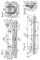
- the linear peristaltic pump has two plates 1 and 2 braced by two crosspieces 3 and 4 to which they are rigidly fixed in order to form a removable chassis 5.
- the chassis is guided in translation perpendicular to a substantially flat sole 6 belonging to a fixed frame 7 not shown.
- the sole 6 is integral with the barrel 8 of four columns 9 extended, beyond shoulders 10, by guide rods 11 on which are threaded the ends of the crosspieces 3 and 4 projecting from the plates.
- These ends of the sleepers are applied elastically against the shoulders 10 by elastic suspensions, such as elastomer blocks 12 or any other equivalent means: springs, pneumatic cylinders ... bearing against the end stops 13 of said rods.
- This pipe can be made of relatively thick rubber, because it must convey concrete under pressure and return by elastic return from a flattened obturation section ( Figures 1, 2 and 6) to a circular transport section ( Figures 1 and 5).
- the chassis 5 supports pressure rollers 15, 16, 17 extending transversely between the plates 1 and 2.
- Each of the rollers 15 to 17 is mounted idly around an axis 18 supported by two rollers 19.1 and 19.2 resting on bearing 20.1 and 20.2 formed by the edges of the plates 1 and 2.
- the projecting ends 21.1 and 21.2 of the axes of the three rollers are fixed to links of two endless chains 22.1 and 22.2, links which are selected so that said rollers are equidistant from each other each other.
- the chains 22.1 and 22.2 mesh on the one hand, with two pairs of extreme toothed wheels 23.1, 23.2 and 24.1, 24.2, on the other hand, with two pairs of return sprockets 25.1, 25.2 and 26.1, 26.2.
- Wheels 23 and 24 are fixed on shafts 27 and 28 supported by the plates 1 and 2 of the chassis, one of these shafts being driving and connected to a device (not shown) for driving in rotation in the direction of the arrow F .
- the return gears 25 and 26 are wedged on shafts 29 and 30 aligned and supported overhang by said plates or ferries.
- the chains 22.1, 22.2 and the raceways 20.1, 20.2 are equidistant. It is very important to note that the plates are shaped as trapezoids, the small base 31 of which, located near the sole 6 and the pipe 14 which is supported thereon, is connected to the extreme rounded edges 32, 33 of the large base by cams 34, 35. These cams are intended to determine respectively the engaging engaging portion 36 and the clearing erasing portion 37 located at the ends of the linear pumping portion 38 of the active path of the rollers 15 to 17. Therefore , the cams 34 are shaped to control the progressiveness of the attack and their shape which on the whole is sloping depends on the law chosen.
- these driving cams 34 are inclined ramps tangent to the rounded 32 and connected to the rectilinear parts 31. In the example shown, they form an angle "a" with these parts 31, angle which is preferably equal to 20 ° ; it can however vary between 15 and 40 ° .
- the return gears 25.1 and 25.2 are then located at the connection of the ramps 34 with the rectilinear parts 31.
- the drawing clearly shows that the exhaust cams 35 extend symmetrically to the driving cams 34 relative to the median plane P.
- the inclined ramps of attack 34 are connected to the straight portions 31 by inclined ramps of finish 39 allowing the crushing of the pipe 14. It can also be the same for the inclined ramps exhaust 35 which are then preceded by inclined priming ramps 40 promoting the opening of the pipe 14 for the delivery of concrete.
- the finishing or crushing ramps 39 form an angle "b" with the straight portions 31 and the priming ramps 40 are advantageously symmetrical with the preceding ones relative to the plane P.
- the angle b is between 3 and 15 ° and preferably equal to 5 °.
- the return gears 25.1 and 25.2 are located in the area of connection of the ramps 34 and 35 with the ramps 39 and 40 respectively.
- downstream ramps 35 and 40 are useful especially when the chains 22 are driven in reverse to unclog the pipe 14.
- the distance "d" of the two cams or ramps 34 and 35 is such that, compared to the distance "D" separating two consecutive rollers (16 and 17 for example), the passages 41 and 42 delimited by the pipe 14 pinched opposite two rollers, when these are arranged symmetrically with respect to the plane P, have the same free section and from this position, the upstream passage 41 narrows while the downstream passage 42 increases.
- the excess concrete can flow both downstream and upstream through the passages 41 and 42.
- the concrete does not tend, because of its high viscosity, to reverse its direction of flow to return upstream through these passages.
- the downstream passage 42 increases while the upstream passage 41 narrows, concrete tends to continue to flow downstream or to momentarily stagnate, but not to flow back upstream.
- the equal sections of the passages 41 and 42 have a height preferably substantially equal to the size of the largest gravel.
- the roller which follows this part keeps the pipe 14 crushed and while rolling pushes back the concrete of the corresponding section.
- the segregation of the gravel does not occur and these then accompany the pasty mass in front of the roller. But sometimes gravel gets stuck between the two folds of the pipe.
- the frame 5 is then raised against the action of the elastic suspensions 12, especially if the gravel is large, to avoid laceration of the internal wall of said pipe and after crossing the gravel returns to the crushing position in which the crosspieces 3, 4 are pressed against the shoulders 10 of the columns, position in which the sealing of the pipe is ensured in the areas pinched by the rollers.
- a safety device must intervene and, at the limit, causes the pump to stop.
- a detection member 43 (FIG. 1), such as a microswitch, is mounted on the fixed frame 7 so that its movable element can be urged by the chassis 5 during its lifting beyond a certain limit ; this microswitch is inserted in the safety circuit of the pump control unit.
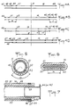
- the wear of the pipe 14 by abrasion and laceration is not uniform and its maximum is located in the zone U (FIG. 3) corresponding to the crushing at the end of the attack.
- the pipe 14 is provided at its ends with connection flanges 44 and 45 allowing it to be integrated into the circuit of the installation. It cooperates with an extension 46, the extreme flanges 47 and 48 of which can be selectively connected to the flange 44 or 45 of the pipe to form an assembly, the two flanges of which remain free must then be fixed on those awaiting the circuit.
- This assembly 14, 46 is positioned in such a way that its end flanges are arranged symmetrically with respect to the plane P. These are, for example, flanges 45 and 47 in the initial assembly according to FIG. 4A.
- the end flange 44 of the pipe 14 is located in the vicinity of the wear zone U (FIG. 3).
- the replacement of the pipe 14 is carried out only after wear in four zones U.1 to U.4 distributed over its length.
- the pipe is then used in almost its entire extent, since the abrasion wear along the straight part 38 of the path lasts four times longer than in each of the zones U.1 to U.4, by abrasion and laceration.
- zones U.1 and U.2, as well as that of zones U.3 and U.4 is equal to the length I of the extension; the distance from zones U.2 and U.3 is equal to the difference 2L-1.
- the length "I" of the extension is less than the distance "L" above.
- the elastomer wall 49 of the pipe 14 is relatively thick and coats two plies of transverse reinforcements 50 and 51, these reinforcements being preferably metallic and wound in counter concentric helices .
- a third layer of reinforcements 52 are provided. These, preferably metallic, extend longitudinally and parallel to each other. others, to form a ply located in the vicinity of the sole 6 and covering a limited width "m". This width is between 5 and 35% of the circumferential development of the pipe at the same radius; it is preferably equal to 10%.
- the inner layer of elastomer is advantageous for the inner layer of elastomer to be much thicker than the outer layer, relative to the three reinforcing plies, given that c 'is mainly the inner layer which is subject to wear.
- the longitudinal reinforcement ply 52 extends outside the two transverse reinforcement plies 50 and 51, but it is obvious that this longitudinal reinforcement ply could be located between the two transverse plies or at inside these two layers.
- each end of the pipe 14 is equipped with a connection flange 44 (or 45); in the example shown, this flange protrudes from a connection sleeve 53 fitted into the end considered of the pipe and fixed by means of a collar 54.
- the longitudinal reinforcements 52 are tensioned and each of their ends is fixed to the corresponding connection means.
- slots 55 are sliced at the end of the pipe opposite said frames to release them and take them; the ends of these are then bent to form loops 56 covering the collar 54; a second collar 57 is then fitted onto these loops and tightened on the first 54 in order to ensure firm and solid fixing of said frames.
- the monolithism of the chassis 5, instead of being provided by the crosspieces 3 and 4, can be, as shown in FIG. 2A, by the transverse shafts 29 and 30; in this case, these shafts 29 and 30 pass through the pinions 25.1 and 25.2, 26.1 and 26.2 respectively and protrude outside of them; the projecting parts 30A of the shafts are then mounted journalling in bearings with elastic rings 12A replacing the elastic elements 12, bearings which are then supported by the columns 9.
- This alternative embodiment has the advantage of allowing the disassembly of the pipe from a very convenient, simply by disengaging the bearings from one of the shafts and tilting the frame around the bearings of the other shaft.
Landscapes
- Engineering & Computer Science (AREA)
- Mechanical Engineering (AREA)
- General Engineering & Computer Science (AREA)
- Reciprocating Pumps (AREA)
Claims (17)
Applications Claiming Priority (2)
| Application Number | Priority Date | Filing Date | Title |
|---|---|---|---|
| FR8506583A FR2581133B1 (fr) | 1985-04-30 | 1985-04-30 | Pompe peristaltique lineaire pour vehiculer du beton ou autre |
| FR8506583 | 1985-04-30 |
Publications (2)
| Publication Number | Publication Date |
|---|---|
| EP0201389A1 EP0201389A1 (de) | 1986-11-12 |
| EP0201389B1 true EP0201389B1 (de) | 1989-10-04 |
Family
ID=9318840
Family Applications (1)
| Application Number | Title | Priority Date | Filing Date |
|---|---|---|---|
| EP86400824A Expired EP0201389B1 (de) | 1985-04-30 | 1986-04-17 | Lineare peristaltische Pumpe zum Transportieren von Beton oder anderen Materialien |
Country Status (5)
| Country | Link |
|---|---|
| US (1) | US4735553A (de) |
| EP (1) | EP0201389B1 (de) |
| DE (1) | DE3666073D1 (de) |
| ES (1) | ES8704591A1 (de) |
| FR (1) | FR2581133B1 (de) |
Families Citing this family (11)
| Publication number | Priority date | Publication date | Assignee | Title |
|---|---|---|---|---|
| US5380172A (en) * | 1993-12-29 | 1995-01-10 | Ulbing; Otmar | Peristaltic action precision pump filler |
| CH689841A5 (it) * | 1994-11-18 | 1999-12-15 | Soremartec Sa | Dispositivo per l'erogazione controllata di sostanze, ad esempio sostanze alimentari. |
| DE19824960A1 (de) * | 1998-06-04 | 1999-12-16 | Fuelltec Gmbh | Füllvorrichtung |
| ITPI20040037A1 (it) * | 2004-05-24 | 2004-08-24 | Alessandro Bertocchi | Metodo per il trasferimento di prodotti in impianti per la produzione di purea e dispositivo che attua tale metodo |
| US20060228240A1 (en) * | 2005-03-30 | 2006-10-12 | Lancer Partnership, Ltd. | Method and apparatus for a linear peristaltic pump |
| NL2000058C2 (nl) * | 2006-04-21 | 2007-10-23 | Bredel Hose Pumps B V | Peristaltische pomp. |
| DE102007034125A1 (de) * | 2007-07-21 | 2009-01-22 | Rolf Kammerer | Verdrängerpumpe |
| US8074809B2 (en) * | 2009-07-17 | 2011-12-13 | Gordon H. King | Apparatus and method for the treatment of liquid/solid mixtures |
| US8241018B2 (en) | 2009-09-10 | 2012-08-14 | Tyco Healthcare Group Lp | Compact peristaltic medical pump |
| FR2991010B1 (fr) * | 2012-05-23 | 2019-05-10 | Physidia | Pompe peristaltique lineaire |
| JP6815827B2 (ja) * | 2016-10-26 | 2021-01-20 | サントリーホールディングス株式会社 | 注出ポンプ及び液体ディスペンサ |
Family Cites Families (12)
| Publication number | Priority date | Publication date | Assignee | Title |
|---|---|---|---|---|
| CA577378A (en) * | 1959-06-09 | Andres Ferrari, Jr. | Pump of the compressible tube type | |
| US2865303A (en) * | 1954-10-22 | 1958-12-23 | Technicon Instr | Pumps |
| US3138111A (en) * | 1962-11-21 | 1964-06-23 | Technicon Instruements Corp | Multiple tube pump |
| US3582234A (en) * | 1969-07-14 | 1971-06-01 | Technicon Corp | Method and apparatus for the calibration of tubing to provide for a desired flow rate therethrough |
| US3628891A (en) * | 1970-09-14 | 1971-12-21 | Technicon Corp | Method for the minimization of the effects of pulsations in intermittent pumping systems |
| CS162875B1 (de) * | 1970-12-23 | 1975-07-15 | ||
| US3712762A (en) * | 1971-03-19 | 1973-01-23 | Hansmann A | Concrete pump |
| DE2354897C3 (de) * | 1973-11-02 | 1978-07-20 | Danfoss A/S, Nordborg (Daenemark) | Gekapselte Kältemaschine |
| JPS53122117A (en) * | 1977-03-31 | 1978-10-25 | Hitachi Ltd | Pump automatic operation device |
| JPS57108487A (en) * | 1980-12-24 | 1982-07-06 | Daiichi Kikai Kogyo Kk | Squeeze pump |
| DE3327669A1 (de) * | 1983-07-30 | 1985-02-07 | Continental Gummi-Werke Ag, 3000 Hannover | Schlauch fuer schlauchpumpen |
| FR2559214A1 (fr) * | 1984-02-08 | 1985-08-09 | Levi Andre | Pompe volumetrique a action multiple et a debit reglable |
-
1985
- 1985-04-30 FR FR8506583A patent/FR2581133B1/fr not_active Expired
-
1986
- 1986-04-17 EP EP86400824A patent/EP0201389B1/de not_active Expired
- 1986-04-17 DE DE8686400824T patent/DE3666073D1/de not_active Expired
- 1986-04-25 US US06/856,662 patent/US4735553A/en not_active Expired - Fee Related
- 1986-04-29 ES ES554525A patent/ES8704591A1/es not_active Expired
Also Published As
| Publication number | Publication date |
|---|---|
| ES8704591A1 (es) | 1987-04-01 |
| DE3666073D1 (en) | 1989-11-09 |
| EP0201389A1 (de) | 1986-11-12 |
| ES554525A0 (es) | 1987-04-01 |
| FR2581133A1 (fr) | 1986-10-31 |
| FR2581133B1 (fr) | 1987-07-24 |
| US4735553A (en) | 1988-04-05 |
Similar Documents
| Publication | Publication Date | Title |
|---|---|---|
| EP0201389B1 (de) | Lineare peristaltische Pumpe zum Transportieren von Beton oder anderen Materialien | |
| EP2232075B1 (de) | Erweiterte peristaltische pumpe | |
| BE1023773B1 (fr) | Dispositif d’extension et de retraction d’un tuyau flexible d’air conditionne pour aeronefs au sol | |
| FR2477057A1 (fr) | Procede et appareillage pour la fabrication de tuiles en beton | |
| EP0026704B1 (de) | Peristaltische Pumpe | |
| CA2056247C (fr) | Dispositif a ruban metallique articule, notamment pour le deplacement de charges lourdes | |
| EP0311526B1 (de) | Filterpresse mit endlosen Filterbändern | |
| FR2943045A1 (fr) | Bande transporteuse sans fin deformable transversalement, pour dispositif convoyeur | |
| EP2239064A1 (de) | Reinigungssystem mit Hilfe von Kugeln, insbesondere für Plattenwärmetauscher | |
| EP3478584B1 (de) | Vorrichtung mit einem antriebssystem zum ausfahren und einziehen eines schlauchs für klimatisierte luft | |
| EP2303729A1 (de) | Endlosträgerband für fördersystem oder damit ausgestattetes fördersystem | |
| WO2005123552A1 (fr) | Bande de convoyage et convoyeur comportant une telle bande | |
| FR2966526A1 (fr) | Pompe peristaltique | |
| FR2852266A1 (fr) | Dispositif de pressage pour presse de dehydratation | |
| EP0588737B1 (de) | Vorrichtung zum kontinuierlichen Zuführen einer Lanze zum Spritzen einer homogenen Mischung aus Partikeln bestehender trockener oder feuchter Stoffe | |
| FR2597520A1 (fr) | Perfectionnements aux dispositifs pour supporter des charges lourdes et mobiles | |
| FR3061048A1 (fr) | Methode et installation de reglage du pas des spires d'une carcasse metallique | |
| CH640776A5 (fr) | Procede et dispositif pour la fabrication de conduites cambrees en materiau composite. | |
| FR2515296A1 (fr) | Courroie trapezoidale a elements de friction rigides rapportes | |
| FR2728497A1 (fr) | Dispositif de decoupage de fibre | |
| EP0741206B1 (de) | Überlaufklappenwehr | |
| FR2981993A1 (fr) | Pompe a engrenages a cylindree variable pour turbomachine d'aeronef | |
| FR2759359A1 (fr) | Dispositif de pliage et d'evacuation de linge, pour secheuse repasseuse et secheuse repasseuse incorporant un tel dispositif | |
| WO2015023171A1 (fr) | Station support a un seul rouleau concave pour la mise en auge d'une bande transporteuse et convoyeur la comportant | |
| WO2007057609A1 (fr) | Machine de coupe automatique de materiaux en feuille a caisson de depression bombe |
Legal Events
| Date | Code | Title | Description |
|---|---|---|---|
| PUAI | Public reference made under article 153(3) epc to a published international application that has entered the european phase |
Free format text: ORIGINAL CODE: 0009012 |
|
| AK | Designated contracting states |
Kind code of ref document: A1 Designated state(s): BE CH DE GB IT LI |
|
| PUAB | Information related to the publication of an a document modified or deleted |
Free format text: ORIGINAL CODE: 0009199EPPU |
|
| PUAF | Information related to the publication of a search report (a3 document) modified or deleted |
Free format text: ORIGINAL CODE: 0009199SEPU |
|
| R17D | Deferred search report published (corrected) |
Effective date: 19861217 |
|
| RA1 | Application published (corrected) |
Date of ref document: 19861217 Kind code of ref document: A1 |
|
| 17P | Request for examination filed |
Effective date: 19870723 |
|
| 17Q | First examination report despatched |
Effective date: 19881018 |
|
| GRAA | (expected) grant |
Free format text: ORIGINAL CODE: 0009210 |
|
| AK | Designated contracting states |
Kind code of ref document: B1 Designated state(s): BE CH DE GB IT LI |
|
| PG25 | Lapsed in a contracting state [announced via postgrant information from national office to epo] |
Ref country code: GB Effective date: 19891004 |
|
| ITF | It: translation for a ep patent filed | ||
| REF | Corresponds to: |
Ref document number: 3666073 Country of ref document: DE Date of ref document: 19891109 |
|
| GBV | Gb: ep patent (uk) treated as always having been void in accordance with gb section 77(7)/1977 [no translation filed] | ||
| PGFP | Annual fee paid to national office [announced via postgrant information from national office to epo] |
Ref country code: CH Payment date: 19900412 Year of fee payment: 5 |
|
| PGFP | Annual fee paid to national office [announced via postgrant information from national office to epo] |
Ref country code: BE Payment date: 19900515 Year of fee payment: 5 |
|
| PLBE | No opposition filed within time limit |
Free format text: ORIGINAL CODE: 0009261 |
|
| STAA | Information on the status of an ep patent application or granted ep patent |
Free format text: STATUS: NO OPPOSITION FILED WITHIN TIME LIMIT |
|
| 26N | No opposition filed | ||
| PG25 | Lapsed in a contracting state [announced via postgrant information from national office to epo] |
Ref country code: LI Effective date: 19910430 Ref country code: CH Effective date: 19910430 Ref country code: BE Effective date: 19910430 |
|
| BERE | Be: lapsed |
Owner name: VIDAL LUCIEN RENE Effective date: 19910430 |
|
| REG | Reference to a national code |
Ref country code: CH Ref legal event code: PL |
|
| PGFP | Annual fee paid to national office [announced via postgrant information from national office to epo] |
Ref country code: DE Payment date: 19930423 Year of fee payment: 8 |
|
| ITTA | It: last paid annual fee | ||
| PG25 | Lapsed in a contracting state [announced via postgrant information from national office to epo] |
Ref country code: DE Effective date: 19950103 |
|
| PG25 | Lapsed in a contracting state [announced via postgrant information from national office to epo] |
Ref country code: IT Free format text: LAPSE BECAUSE OF NON-PAYMENT OF DUE FEES;WARNING: LAPSES OF ITALIAN PATENTS WITH EFFECTIVE DATE BEFORE 2007 MAY HAVE OCCURRED AT ANY TIME BEFORE 2007. THE CORRECT EFFECTIVE DATE MAY BE DIFFERENT FROM THE ONE RECORDED. Effective date: 20050417 |