EP0201418A1 - Vorrichtung zum Verankern von angespannten Seilen - Google Patents
Vorrichtung zum Verankern von angespannten Seilen Download PDFInfo
- Publication number
- EP0201418A1 EP0201418A1 EP86400952A EP86400952A EP0201418A1 EP 0201418 A1 EP0201418 A1 EP 0201418A1 EP 86400952 A EP86400952 A EP 86400952A EP 86400952 A EP86400952 A EP 86400952A EP 0201418 A1 EP0201418 A1 EP 0201418A1
- Authority
- EP
- European Patent Office
- Prior art keywords
- shoulder
- head
- anchoring
- cable
- bearing surface
- Prior art date
- Legal status (The legal status is an assumption and is not a legal conclusion. Google has not performed a legal analysis and makes no representation as to the accuracy of the status listed.)
- Granted
Links
- 238000004873 anchoring Methods 0.000 title claims abstract description 31
- 230000001112 coagulating effect Effects 0.000 claims description 4
- 239000007788 liquid Substances 0.000 claims description 2
- 239000000463 material Substances 0.000 description 2
- 239000002184 metal Substances 0.000 description 2
- 230000000284 resting effect Effects 0.000 description 2
- 230000000295 complement effect Effects 0.000 description 1
- 230000000694 effects Effects 0.000 description 1
- 238000009434 installation Methods 0.000 description 1
- 239000000314 lubricant Substances 0.000 description 1
- 239000010687 lubricating oil Substances 0.000 description 1
- 239000010705 motor oil Substances 0.000 description 1
- 230000003071 parasitic effect Effects 0.000 description 1
- 238000004064 recycling Methods 0.000 description 1
- 239000011150 reinforced concrete Substances 0.000 description 1
- 239000007787 solid Substances 0.000 description 1
- 239000000725 suspension Substances 0.000 description 1
Images
Classifications
-
- E—FIXED CONSTRUCTIONS
- E04—BUILDING
- E04G—SCAFFOLDING; FORMS; SHUTTERING; BUILDING IMPLEMENTS OR AIDS, OR THEIR USE; HANDLING BUILDING MATERIALS ON THE SITE; REPAIRING, BREAKING-UP OR OTHER WORK ON EXISTING BUILDINGS
- E04G21/00—Preparing, conveying, or working-up building materials or building elements in situ; Other devices or measures for constructional work
- E04G21/12—Mounting of reinforcing inserts; Prestressing
- E04G21/121—Construction of stressing jacks
-
- E—FIXED CONSTRUCTIONS
- E01—CONSTRUCTION OF ROADS, RAILWAYS, OR BRIDGES
- E01D—CONSTRUCTION OF BRIDGES, ELEVATED ROADWAYS OR VIADUCTS; ASSEMBLY OF BRIDGES
- E01D19/00—Structural or constructional details of bridges
- E01D19/14—Towers; Anchors ; Connection of cables to bridge parts; Saddle supports
-
- E—FIXED CONSTRUCTIONS
- E04—BUILDING
- E04C—STRUCTURAL ELEMENTS; BUILDING MATERIALS
- E04C5/00—Reinforcing elements, e.g. for concrete; Auxiliary elements therefor
- E04C5/08—Members specially adapted to be used in prestressed constructions
- E04C5/12—Anchoring devices
- E04C5/125—Anchoring devices the tensile members are profiled to ensure the anchorage, e.g. when provided with screw-thread, bulges, corrugations
Definitions
- the invention relates to anchoring devices for stretched cables and more particularly those of these devices, for which relative variations in inclination are likely to appear between the device and the cable when the latter is loaded.
- Such cables are, for example, the cables making up the stay cables for the suspension of bridges: the overloads applied to these bridges after the installation of their stay cables can indeed slightly deform their suspended decks and therefore the inclinations of the cables relative to their devices. anchoring or vice versa.
- the cable traction cylinder is then itself mounted on the ball joint around this cable.
- the cable pulling cylinder, surrounding the anchoring head is not mounted on the ball joint integral with this head, but on a second ball joint larger than the first and itself received in a second bowl carried by the first, this formula makes it possible to make the cylinder coaxial with the anchoring head even when the latter is inclined relative to normal to the flat surfaces for carrying the plate and the bowls, and therefore exert pulls on the cable so "inclined", but it does not vary the inclination of the anchor heads under load.
- the invention aims, above all, to make possible such variations under load.
- the anchoring devices of the type in question according to the invention also comprise a traction cylinder arranged around the anchoring head and a convex spherical bearing secured to this head and capable of interacting with an annular bearing of the plate, and they are essentially characterized in that they comprise an annular shoulder attached to the free end of the anchoring head and delimited on the side of the plate by a second convex spherical bearing concentric with the first and in that the cylinder is interposed between the plate and the shoulder and has a concave spherical bearing capable of interacting with the convex spherical bearing of the shoulder so as to make possible a sliding under load of this shoulder relative to the jack.
- the invention includes, apart from these main provisions, certain other provisions which are preferably used at the same time and which will be more explicitly discussed below.
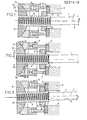
- Figure 1 of this drawing shows schematically in axial section a cable anchoring device established in accordance with the invention after tilting the cable under load and before correcting the orientation of the anchoring head.
- Figures 2 and 3 show substantially the same device respectively during the correction and after it.
- the tensioning cable 1 which is for example intended for the guying of a bridge, is terminated by a rigid head 2 externally threaded.
- this head 2 that is to be anchored.
- a solid 3 made of metal or reinforced concrete, hollowed out by a hole 4 of axis X suitable for delivering passage to the cable 1, or more precisely on a annular metal support plate 5 attached to this block 3 and hollowed out like this.
- said head 2 or “anchoring head” is surrounded by a nut 6 screwed onto it and itself having a convex spherical bearing 7 suitable for resting on an appropriate annular bearing 8 of the plate 5, carried coaxial with hole 4 and generally frustoconical.
- the two spherical surfaces 10 and 14 have the same radius of curvature and at least one of these surfaces is made of a hard and non-deformable material. They are machined and treated in such a way that they can easily slide against each other even under load and so that the axis of the head 2 can align rigorously with that of the cable 1 harnessed on this same head when this cable is heavily loaded.
- liquid lubricant such as engine oil
- This lubricant is discharged to the interface concerned under a high pressure (for example between 500 to 1,000 bars) through pipes 16 and distribution grooves 17, then recovered in the state of leakage on the edges of the surface.
- a high pressure for example between 500 to 1,000 bars
- the shoulder 9 is preferably removably mounted on the head 2, for example by screwing, so that it can be recovered just like the jack 11 in order to successively correct the orientations of separate heads 2.
- the head 2 of this cable, anchored on the block 3 is coaxial with the hole 4 of axis X and the nut 6 is oriented coaxially to this hole with its bearing surface 7 resting on the bearing surface 8 of the plate 5.
- the Y axis of the cable 1 occupies an inclined position at an angle ⁇ relative to the X axis ( Figure 1).
- the interface between the spherical bearings 10 and 14 is lubricated in the manner specified above.
Landscapes
- Engineering & Computer Science (AREA)
- Architecture (AREA)
- Civil Engineering (AREA)
- Structural Engineering (AREA)
- Mechanical Engineering (AREA)
- Piles And Underground Anchors (AREA)
- Bridges Or Land Bridges (AREA)
- Cable Accessories (AREA)
- Laying Of Electric Cables Or Lines Outside (AREA)
- Reinforcement Elements For Buildings (AREA)
- Tension Adjustment In Filamentary Materials (AREA)
Priority Applications (1)
| Application Number | Priority Date | Filing Date | Title |
|---|---|---|---|
| AT86400952T ATE35707T1 (de) | 1985-05-03 | 1986-04-30 | Vorrichtung zum verankern von angespannten seilen. |
Applications Claiming Priority (2)
| Application Number | Priority Date | Filing Date | Title |
|---|---|---|---|
| FR8506773A FR2581409B1 (fr) | 1985-05-03 | 1985-05-03 | Perfectionnements aux dispositifs d'ancrage pour cables tendus |
| FR8506773 | 1985-05-03 |
Publications (2)
| Publication Number | Publication Date |
|---|---|
| EP0201418A1 true EP0201418A1 (de) | 1986-11-12 |
| EP0201418B1 EP0201418B1 (de) | 1988-07-13 |
Family
ID=9318945
Family Applications (1)
| Application Number | Title | Priority Date | Filing Date |
|---|---|---|---|
| EP86400952A Expired EP0201418B1 (de) | 1985-05-03 | 1986-04-30 | Vorrichtung zum Verankern von angespannten Seilen |
Country Status (7)
| Country | Link |
|---|---|
| EP (1) | EP0201418B1 (de) |
| AT (1) | ATE35707T1 (de) |
| DE (1) | DE3660384D1 (de) |
| DK (1) | DK159623C (de) |
| ES (1) | ES296779Y (de) |
| FR (1) | FR2581409B1 (de) |
| NO (1) | NO165255C (de) |
Cited By (6)
| Publication number | Priority date | Publication date | Assignee | Title |
|---|---|---|---|---|
| FR2664928A1 (fr) * | 1990-07-23 | 1992-01-24 | Leguern Jacques | Batiment de stockage de produits en vrac et procede de fabrication de ce batiment. |
| EP0632175A3 (de) * | 1993-07-01 | 1995-05-24 | Alex Zehnder | Tragseillagerung. |
| FR2730511A1 (fr) * | 1995-02-13 | 1996-08-14 | Mure Ets | Dispositif d'ancrage mutuel de deux parois |
| GB2366314A (en) * | 2000-06-27 | 2002-03-06 | Crawford Moya | Apparatus for reducing motion on suspension type bridges |
| WO2002016710A3 (de) * | 2000-08-16 | 2002-08-01 | Josef Scherer | Vorrichtung zum spannen von verstärkungselementen |
| ITMI20102112A1 (it) * | 2010-11-15 | 2012-05-16 | Ttm Tension Technology S R L | Gruppo di supporto per l'installazione e il fissaggio di tiranti inclinati |
Citations (2)
| Publication number | Priority date | Publication date | Assignee | Title |
|---|---|---|---|---|
| DE1409162A1 (de) * | 1958-05-02 | 1968-11-14 | Vorspann Technik Gmbh | Verfahren und Vorrichtung zum Verankern von starren Staeben als Vorspannglieder von Baukoerpern aus Beton oder anderen Massen |
| FR2507232A1 (fr) * | 1981-06-09 | 1982-12-10 | Freyssinet Int Stup | Dispositif de mise en tension de barres de precontrainte et de determination de cette tension |
-
1985
- 1985-05-03 FR FR8506773A patent/FR2581409B1/fr not_active Expired
-
1986
- 1986-04-29 ES ES1986296779U patent/ES296779Y/es not_active Expired
- 1986-04-30 EP EP86400952A patent/EP0201418B1/de not_active Expired
- 1986-04-30 AT AT86400952T patent/ATE35707T1/de not_active IP Right Cessation
- 1986-04-30 NO NO861714A patent/NO165255C/no unknown
- 1986-04-30 DE DE8686400952T patent/DE3660384D1/de not_active Expired
- 1986-05-02 DK DK204286A patent/DK159623C/da not_active IP Right Cessation
Patent Citations (2)
| Publication number | Priority date | Publication date | Assignee | Title |
|---|---|---|---|---|
| DE1409162A1 (de) * | 1958-05-02 | 1968-11-14 | Vorspann Technik Gmbh | Verfahren und Vorrichtung zum Verankern von starren Staeben als Vorspannglieder von Baukoerpern aus Beton oder anderen Massen |
| FR2507232A1 (fr) * | 1981-06-09 | 1982-12-10 | Freyssinet Int Stup | Dispositif de mise en tension de barres de precontrainte et de determination de cette tension |
Cited By (7)
| Publication number | Priority date | Publication date | Assignee | Title |
|---|---|---|---|---|
| FR2664928A1 (fr) * | 1990-07-23 | 1992-01-24 | Leguern Jacques | Batiment de stockage de produits en vrac et procede de fabrication de ce batiment. |
| EP0632175A3 (de) * | 1993-07-01 | 1995-05-24 | Alex Zehnder | Tragseillagerung. |
| FR2730511A1 (fr) * | 1995-02-13 | 1996-08-14 | Mure Ets | Dispositif d'ancrage mutuel de deux parois |
| GB2366314A (en) * | 2000-06-27 | 2002-03-06 | Crawford Moya | Apparatus for reducing motion on suspension type bridges |
| GB2366314B (en) * | 2000-06-27 | 2004-03-31 | Crawford Moya | Suspension-type Structure |
| WO2002016710A3 (de) * | 2000-08-16 | 2002-08-01 | Josef Scherer | Vorrichtung zum spannen von verstärkungselementen |
| ITMI20102112A1 (it) * | 2010-11-15 | 2012-05-16 | Ttm Tension Technology S R L | Gruppo di supporto per l'installazione e il fissaggio di tiranti inclinati |
Also Published As
| Publication number | Publication date |
|---|---|
| ES296779Y (es) | 1988-09-16 |
| DK159623B (da) | 1990-11-05 |
| DK159623C (da) | 1991-04-15 |
| NO861714L (no) | 1986-11-04 |
| ES296779U (es) | 1988-01-16 |
| ATE35707T1 (de) | 1988-07-15 |
| EP0201418B1 (de) | 1988-07-13 |
| FR2581409A1 (fr) | 1986-11-07 |
| DK204286D0 (da) | 1986-05-02 |
| FR2581409B1 (fr) | 1987-07-10 |
| DE3660384D1 (en) | 1988-08-18 |
| NO165255B (no) | 1990-10-08 |
| DK204286A (da) | 1986-11-04 |
| NO165255C (no) | 1991-01-16 |
Similar Documents
| Publication | Publication Date | Title |
|---|---|---|
| EP1269059B1 (de) | Ermüdungsbeständiges rohrförmiges gewindeelement mit rille | |
| EP1148207B1 (de) | Verbindungsvorrichtung für eine Unterwasser-Flüssigkeitstransportleitung | |
| EP0254630B1 (de) | Verbindungsvorrichtung zur schnellen Demontage unter Last | |
| EP1231138B1 (de) | Triebwerkaufhängungsvorrichtung an einem Luftfahrzeug | |
| EP0201418B1 (de) | Vorrichtung zum Verankern von angespannten Seilen | |
| WO1999024320A1 (fr) | Dispositif d'accrochage d'un moteur sur un aeronef | |
| EP3626624B1 (de) | Montageverfahren von einem pylon eines flugzeugs | |
| EP0803464B1 (de) | Übertragungsvorrichtung, insbesondere für Fussgänger, zwischen zwei nacheinander in Reihe angeordneten, Förderungselementen, und Fördervorrichtung mit solcher Vorrichtung ausgestattet | |
| WO2019029976A1 (fr) | Anti-rotation a cables | |
| EP1877299A1 (de) | Sattelstangenträgervorrichtung | |
| FR2853304A1 (fr) | Dispositif pour deplacer une charge lourde | |
| EP0517865A1 (de) | Vorrichtung zur end-zu-end-verbindung von zwei stäben | |
| EP1110857A2 (de) | Vorrichtung zur Stabilisierung eines Schiffes, insbesondere beim Rollen | |
| CA1192170A (fr) | Tete visseuse a friction controlee par couple de torsion pour la mise en place de capsules | |
| FR2944078A1 (fr) | Dispositif lineaire a friction controlee avec pressage normal au deplacement | |
| FR3131734A1 (fr) | Ensemble propulsif pour aéronef comportant un turboréacteur, un mât et des moyens d’accrochage du turboréacteur au mât | |
| WO2000050800A1 (fr) | Dispositif de connexion pour le raccordement d'une extremite de conduite a un organe | |
| EP1569842B1 (de) | Fahrradgabelzusammenbau und lenkkopf auf einem fahrradrahmen und gabel für einen solchen zusammenbau | |
| CA3207318A1 (fr) | Dispositif de deplacement d'une charge roulant sur des rails | |
| FR2798696A1 (fr) | Dispositif de reprise d'efforts pour le mat d'un outil de forage | |
| FR2937350A1 (fr) | Cale de compensation pour assemblage par brochage de poutres en beton arme ou precontraint | |
| EP3019430B1 (de) | Hebering | |
| WO2005021364A1 (fr) | Dispositif de blocage de tige de selle | |
| FR3157453A1 (fr) | Système de protection avec un système de serrage calibré | |
| FR2492797A1 (fr) | Dispositif de commande de l'assiette horizontale d'une plate-forme, d'un equipement ou d'un objet similaire monte a l'extremite d'un bras de manoeuvre articule et/ou extensible |
Legal Events
| Date | Code | Title | Description |
|---|---|---|---|
| PUAI | Public reference made under article 153(3) epc to a published international application that has entered the european phase |
Free format text: ORIGINAL CODE: 0009012 |
|
| AK | Designated contracting states |
Kind code of ref document: A1 Designated state(s): AT BE CH DE GB IT LI NL |
|
| 17P | Request for examination filed |
Effective date: 19861222 |
|
| 17Q | First examination report despatched |
Effective date: 19871130 |
|
| GRAA | (expected) grant |
Free format text: ORIGINAL CODE: 0009210 |
|
| AK | Designated contracting states |
Kind code of ref document: B1 Designated state(s): AT BE CH DE GB IT LI NL |
|
| REF | Corresponds to: |
Ref document number: 35707 Country of ref document: AT Date of ref document: 19880715 Kind code of ref document: T |
|
| ITF | It: translation for a ep patent filed | ||
| GBT | Gb: translation of ep patent filed (gb section 77(6)(a)/1977) | ||
| REF | Corresponds to: |
Ref document number: 3660384 Country of ref document: DE Date of ref document: 19880818 |
|
| PLBI | Opposition filed |
Free format text: ORIGINAL CODE: 0009260 |
|
| 26 | Opposition filed |
Opponent name: DYCKERHOFF & WIDMANN AG Effective date: 19890411 |
|
| RAP4 | Party data changed (patent owner data changed or rights of a patent transferred) |
Owner name: FREYSSINET INTERNATIONAL (STUP) |
|
| NLR1 | Nl: opposition has been filed with the epo |
Opponent name: DYCKERHOFF & WIDMANN AG |
|
| REG | Reference to a national code |
Ref country code: CH Ref legal event code: PFA Free format text: FREYSSINET INTERNATIONAL (STUP) |
|
| PGFP | Annual fee paid to national office [announced via postgrant information from national office to epo] |
Ref country code: AT Payment date: 19930326 Year of fee payment: 8 |
|
| PGFP | Annual fee paid to national office [announced via postgrant information from national office to epo] |
Ref country code: CH Payment date: 19930419 Year of fee payment: 8 |
|
| PGFP | Annual fee paid to national office [announced via postgrant information from national office to epo] |
Ref country code: GB Payment date: 19930423 Year of fee payment: 8 |
|
| PGFP | Annual fee paid to national office [announced via postgrant information from national office to epo] |
Ref country code: DE Payment date: 19930428 Year of fee payment: 8 |
|
| PLBM | Termination of opposition procedure: date of legal effect published |
Free format text: ORIGINAL CODE: 0009276 |
|
| STAA | Information on the status of an ep patent application or granted ep patent |
Free format text: STATUS: OPPOSITION PROCEDURE CLOSED |
|
| ITTA | It: last paid annual fee | ||
| PGFP | Annual fee paid to national office [announced via postgrant information from national office to epo] |
Ref country code: NL Payment date: 19930430 Year of fee payment: 8 |
|
| PGFP | Annual fee paid to national office [announced via postgrant information from national office to epo] |
Ref country code: BE Payment date: 19930513 Year of fee payment: 8 |
|
| 27C | Opposition proceedings terminated |
Effective date: 19900615 |
|
| PG25 | Lapsed in a contracting state [announced via postgrant information from national office to epo] |
Ref country code: LI Effective date: 19940430 Ref country code: GB Effective date: 19940430 Ref country code: CH Effective date: 19940430 Ref country code: BE Effective date: 19940430 Ref country code: AT Effective date: 19940430 |
|
| NLR2 | Nl: decision of opposition | ||
| BERE | Be: lapsed |
Owner name: FREYSSINET INTERNATIONAL (STUP) Effective date: 19940430 |
|
| PG25 | Lapsed in a contracting state [announced via postgrant information from national office to epo] |
Ref country code: NL Effective date: 19941101 |
|
| NLV4 | Nl: lapsed or anulled due to non-payment of the annual fee | ||
| REG | Reference to a national code |
Ref country code: CH Ref legal event code: PL |
|
| PG25 | Lapsed in a contracting state [announced via postgrant information from national office to epo] |
Ref country code: DE Effective date: 19950103 |
|
| GBPC | Gb: european patent ceased through non-payment of renewal fee |
Effective date: 19940430 |
|
| PG25 | Lapsed in a contracting state [announced via postgrant information from national office to epo] |
Ref country code: IT Free format text: LAPSE BECAUSE OF NON-PAYMENT OF DUE FEES;WARNING: LAPSES OF ITALIAN PATENTS WITH EFFECTIVE DATE BEFORE 2007 MAY HAVE OCCURRED AT ANY TIME BEFORE 2007. THE CORRECT EFFECTIVE DATE MAY BE DIFFERENT FROM THE ONE RECORDED. Effective date: 20050430 |