EP0201427B1 - Automatische Gebührensammelvorrichtung und Münzbehälter dafür - Google Patents
Automatische Gebührensammelvorrichtung und Münzbehälter dafür Download PDFInfo
- Publication number
- EP0201427B1 EP0201427B1 EP86400979A EP86400979A EP0201427B1 EP 0201427 B1 EP0201427 B1 EP 0201427B1 EP 86400979 A EP86400979 A EP 86400979A EP 86400979 A EP86400979 A EP 86400979A EP 0201427 B1 EP0201427 B1 EP 0201427B1
- Authority
- EP
- European Patent Office
- Prior art keywords
- box
- plate
- door
- latching
- cash box
- Prior art date
- Legal status (The legal status is an assumption and is not a legal conclusion. Google has not performed a legal analysis and makes no representation as to the accuracy of the status listed.)
- Expired - Lifetime
Links
- 238000000151 deposition Methods 0.000 claims description 2
- 238000009423 ventilation Methods 0.000 claims description 2
- XLYOFNOQVPJJNP-UHFFFAOYSA-N water Substances O XLYOFNOQVPJJNP-UHFFFAOYSA-N 0.000 claims description 2
- 230000008020 evaporation Effects 0.000 claims 1
- 238000001704 evaporation Methods 0.000 claims 1
- 238000010276 construction Methods 0.000 description 2
- 229910000831 Steel Inorganic materials 0.000 description 1
- 208000027418 Wounds and injury Diseases 0.000 description 1
- 238000004873 anchoring Methods 0.000 description 1
- 230000000295 complement effect Effects 0.000 description 1
- 230000006378 damage Effects 0.000 description 1
- 208000014674 injury Diseases 0.000 description 1
- 238000003780 insertion Methods 0.000 description 1
- 230000037431 insertion Effects 0.000 description 1
- 238000000034 method Methods 0.000 description 1
- 230000002093 peripheral effect Effects 0.000 description 1
- 230000003014 reinforcing effect Effects 0.000 description 1
- 230000000284 resting effect Effects 0.000 description 1
- 239000010959 steel Substances 0.000 description 1
Images




Classifications
-
- G—PHYSICS
- G07—CHECKING-DEVICES
- G07D—HANDLING OF COINS OR VALUABLE PAPERS, e.g. TESTING, SORTING BY DENOMINATIONS, COUNTING, DISPENSING, CHANGING OR DEPOSITING
- G07D9/00—Counting coins; Handling of coins not provided for in the other groups of this subclass
-
- G—PHYSICS
- G07—CHECKING-DEVICES
- G07B—TICKET-ISSUING APPARATUS; FARE-REGISTERING APPARATUS; FRANKING APPARATUS
- G07B15/00—Arrangements or apparatus for collecting fares, tolls or entrance fees at one or more control points
- G07B15/06—Arrangements for road pricing or congestion charging of vehicles or vehicle users, e.g. automatic toll systems
- G07B15/066—Arrangements for road pricing or congestion charging of vehicles or vehicle users, e.g. automatic toll systems being coin-operated
-
- G—PHYSICS
- G07—CHECKING-DEVICES
- G07F—COIN-FREED OR LIKE APPARATUS
- G07F9/00—Details other than those peculiar to special kinds or types of apparatus
- G07F9/06—Coin boxes
Definitions
- This invention pertains to automatic toll collecting or similar devices and more particularly, to devices having a cash box which after removal, is completely locked and tamper-proof.
- DE-A 2 156 999 describes a device for collecting coins comprising a housing adapted to accept coins; a cash box removably disposed within the housing, said box having an access opening through which coins may fall into the box and door means for selectively opening and closing said access opening; and control means disposed within said housing for opening said door means when the box is inserted in the housing.
- a primary objective of the present invention is to provide a collecting device with a removal cash box which may be safely removed and transported without fear that its contents may be accessed by unauthorized persons.
- the device for collecting coins according to the invention further comprises means for latching said door means closed after said door means has been opened at least once at any stage of removal of the box from the housing.
- This device can be used in several applications including, but not limited to, toll roads, parking lots, garages, etc.
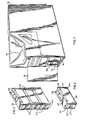
- a vehicle toll collecting device 10 is shown in Figure 1.
- the device is normally adjacent to individual traffic lanes and is provided with a hopper 12 for depositing tokens, coins and the like. After these deposited items are checked for authenticity and counted they are fed into a removable cash box 14.
- cash box 14 is normally housed within a cavity 16 of device 10, behind a normally closed and locked access door 18.
- the box has a preferably rectangular shape with a flat top surface 20 so that a plurality of such boxes may be stacked on top of each other as shown in Figure 3.
- the box has two cavities at its ends, such as at 22, for housing a horizontal handle 24.
- Handle 24 is used to manipulate the box into and out of device 10.
- the handle at inner box end 26 may be engaged by a hook or other similar means (not shown) located within device cavity 16, which may be electronically activated to release the handle.
- box 14 may be removed from device 10 only when an appropriate releasing signal is generated, thereby further insuring that the cash box is not removed by unauthorized personnel.
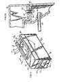
- Box 14 comprises two portions: a main portion 28 which is provided to hold the articles collected from the hopper and a top or cover portion 30 used to close bottom portion 28.
- the two portions 28 and 30 are hingedly connected by hidden hinges 32.
- On top surface 20 of portion 30 there is a shallow, generally rectangular depression 34 extending from box end 26 as shown. Within this depression there is a generally circular access hole 36 covered by a door 38. When the door 38 is in an open position, hole 36 is uncovered and allows access into the box 14.
- Within the depression 34 there is also a curved slot 40 which holds an operating knob 42. This knob extends upwards, but below the top suf- ace 20 so as not to interfere with stacking of multiple cash boxes nor to cause injury to box handlers. Moving knob 42 in the direction 44 (see Figure 4) moves door 38 towards the open position, as shall be described more fully below.
- Portion 30 is also provided with a lock mechanism 46 which may be operated by a security key to lock said portion 30 to portion 28.
- the cash box has a double-walled construction and is made of heavy gauged welded steel so that if it is locked, it is very difficult to open.
- Portion 28 is provided with an inner peripheral ledge 48 connecting its outer wall 50 to an inner vertical lip 52.
- Portion 30 rests on ledge 48 as shown.
- the box 14 is provided with a plurality of support pins 54, and portion 30 has complementary holes 56 corresponding to pins 54 so that if several boxes are stacked the legs 54 engage holes 56 of the corresponding boxes thereby eliminating lateral movement therebetween during transportation. All pin positions and all hole positions may be, as a group, arbitrarily set into upper (cover) portion or bottom portion 28.
- the bottom surface 58 of portion 28 is provided with a plurality of bumps 60 extending into the interior space of the box as shown. These bumps are spaced at a distance smaller than the diameter of the articles collected through hole 36, and are provided to insure that when the box 14 is opened and turned over, none of the articles stick to said bottom surface 58.
- the box is also provided with a plurality of ventilation holes 62 to insure that the interior of the box remains relatively dry and to evacuate any water that may be present inside the box.
- Portion 28 is also provided with one or more reinforcing rods 64 extending horizontally as shown in Figure 6a.
- portion 30 may also be provided with pins 65 shown in Figure 5b welded as at 67 and portion 28 could be formed with corresponding holes 69 for housing pins 65.
- the pins 65 and holes 69 also provides a means of avoiding box deformation, and or unauthorized access to box contents in the event the box falls or is dropped on its ends.
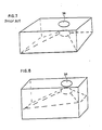
- Prior art cash boxes were constructed so that their width exceeded their height. As a result, as shown in Figure 7, the articles collected within such prior art boxes tended to block the access hole 36 even if when the boxes werely only one third full.
- the present box is constructed so that its height exceeds its width thereby permitting a larger number of articles to be collected before blockage of access hole 36 occurs, as illustrated in Figure 8.
- pin 66 As can be seen in Figure 6, attached to lip 52, there is a vertically extending spring loaded pin 66 which is allowed to move axially. In Figure 6, pin 66 is shown in its maximum extended position.
- Portion 30 is provided with an inner hole 68 adjacent to access hole 36 positioned so that as portion 30 is pivoted to close on portion 28, pin 66 enters through hole 68.
- the function of pin 66 and registering hole 68 shall be described below in conjunction with the operation of access door 38.
- Lock mechanism 46 is mounted on the inner surface of portion 30 as shown in Figure 6.
- the lock mechanism is provided with a sliding tongue 70 operated by a security key in the normal manner.
- the tongue 70 is adapted to engage a slot 72 formed in portion 28 thereby locking portion 28 to portion 30.
- Slot 72 is split into two sections by a wall 74. The two slot sections have a maximum width W which does not exceed the diameter of the collected articles. Thus, when the box is emptied, no articles can be stuck in slot 72.
- Tongue 70 is provided with a slit 76 to match wall 74 as shown.
- Member 78 (shown in Figure 10) adapted to engage the cash box and open its access door 38. This engagement cannot occur if the access hole 36 is open.
- Member 78 is dimensioned so that as cash box 14 is inserted into cavity 16 of device 10, at least a portion of member 78 is positioned within depression 34 below the top surface 20 of the box.
- Member 78 is provided on its bottom surface 80 with a groove 82 having first and second straight portions 84 and 86. The straight portions are offset from each other and joined by an intermediate portion 88.
- the groove 82 is positioned so that as the box 14 is pushed into cavity 16, access door operating-knob is engaged by groove 82.
- the top 20 of portion 30 is double walled so that the door 38 can be housed inside it. Details of the access door 38 are shown in Figure 12.
- the door comprises a plate 90 with a semicircular cut-out 92. The cut-out is provided to insure that when the door 38 is in its open position, it clears access hole 36.
- the plate is provided with a mounting pin 94 used to pivotally mount the door to portion 30.
- a second pin 96 is secured to plate 90 and is provided as an anchoring point for two coil springs 98 and 100. Pin 96 extends through plate 90 to form operating knob 42.
- a T-shaped member 102 is pivotally mounted on pin 94 on top of plate 90 as shown.
- a distal end of coil spring 98 is connected to T-shaped member 102 so that coild spring 98 urges said member 102 against stop 104.
- distal end of coil spring 100 is secured to a stationery pin 106 which is positioned so that coil spring 100 urges the plate 90 towards its closed position.
- the access door 38 is arranged and positioned within portion 30 so that when the portion 30 is initially closed, pin 66 mounted on portion 28 enters through hole 68 ( Figure 6) and is urged against the T-shaped member 102 as shown in Figure 12.
- the access door 38 operates as follows. Prior to the insertion of box 14 into device 10, door 38 closes off hole 36 as shown in Figure 13. As previously mentioned, pin 66 is urged against T-shaped member 102 by spring 104 as shown in Figures 13 and 14. As box 14 is inserted into device 10, operating knob 42 is moved clockwise by groove 82 (as described above) within slot 40 pivoting plate 90 around pin 94 until hole 36 is completely opened as shown in Figure 15. In the open position, coins deposited in device 10 are fed by a hopper (not shown) through hole 36 into box 14.
- pin 66 As the plate 90 moves back through towards the closed portion pin 66 continues to slide across plate 90 until it clears plate edge 110 at which point spring 108 pushes pin 66 upwards past plate 90 as shown in Figure 17 and 18.
- pin 66 is positioned between the T-shaped member 102 and plate 90.
- the door is latched in a closed position any attempt to reopen access door 38 by turning plate 90 clockwise merely brings plate edge 110 into contact with pin 66, and no further. Therefore, pin 66 cooperates with plate 90 and prevents unauthorized access into box 14.
- lock 46 is covered when the box is inserted in device 10 so that the box may be opened by a key only after the box has been removed. Furthermore, hole 36 is made sufficiently small so that a person's hand cannot fit therethrough.
- FIG. 20 Another, somewhat preferred embodiment of the cash box is shown in Figure 20.
- access hole 38' has been shifted to the geometric center of box top surface 20'.
- Figure 21 even more coins can be collected by the box before it overflows.
Landscapes
- Physics & Mathematics (AREA)
- General Physics & Mathematics (AREA)
- Business, Economics & Management (AREA)
- Finance (AREA)
- Control Of Vending Devices And Auxiliary Devices For Vending Devices (AREA)
- Purses, Travelling Bags, Baskets, Or Suitcases (AREA)
- Devices For Checking Fares Or Tickets At Control Points (AREA)
Claims (16)
Applications Claiming Priority (2)
| Application Number | Priority Date | Filing Date | Title |
|---|---|---|---|
| US73146485A | 1985-05-07 | 1985-05-07 | |
| US731464 | 1985-05-07 |
Publications (3)
| Publication Number | Publication Date |
|---|---|
| EP0201427A2 EP0201427A2 (de) | 1986-12-17 |
| EP0201427A3 EP0201427A3 (en) | 1987-01-21 |
| EP0201427B1 true EP0201427B1 (de) | 1990-10-03 |
Family
ID=24939616
Family Applications (1)
| Application Number | Title | Priority Date | Filing Date |
|---|---|---|---|
| EP86400979A Expired - Lifetime EP0201427B1 (de) | 1985-05-07 | 1986-05-06 | Automatische Gebührensammelvorrichtung und Münzbehälter dafür |
Country Status (6)
| Country | Link |
|---|---|
| EP (1) | EP0201427B1 (de) |
| JP (1) | JPS61276097A (de) |
| KR (1) | KR900000226B1 (de) |
| DE (1) | DE3674632D1 (de) |
| ES (1) | ES8706991A1 (de) |
| HK (1) | HK52392A (de) |
Cited By (1)
| Publication number | Priority date | Publication date | Assignee | Title |
|---|---|---|---|---|
| DE4105441A1 (de) * | 1991-02-08 | 1992-08-13 | Elmar Gehrig | Muenzzaehlmaschine mit muenzbehaeltern |
Families Citing this family (14)
| Publication number | Priority date | Publication date | Assignee | Title |
|---|---|---|---|---|
| JPH0238677U (de) * | 1988-09-02 | 1990-03-14 | ||
| FR2639671B1 (fr) * | 1988-11-25 | 1995-06-16 | Guillot Electricite Sa | Coffre mobile de securite a cycle de verrouillage automatique apres ouverture fermeture n'autorisant l'ouverture pour le remplissage que lorsque le coffre est vide |
| US5129330A (en) * | 1991-06-20 | 1992-07-14 | Sigma Game, Inc. | Currency security box |
| GB9610211D0 (en) * | 1996-05-16 | 1996-07-24 | Post Office | Device for opening a container |
| KR100443053B1 (ko) * | 2001-02-19 | 2004-08-04 | 두명테크 주식회사 | 공중전화기용 동전 수거함 |
| KR100438152B1 (ko) * | 2002-06-24 | 2004-07-02 | 비씨아이테크놀로지 주식회사 | 전자투표기용 투표용지보관함 |
| FR2876479B1 (fr) * | 2004-10-11 | 2006-12-15 | Parkeon | Machine a pieces a receptacle de pieces de monnaie amovible |
| NL1031716C2 (nl) * | 2006-04-28 | 2007-10-30 | Pch Holding B V | Opname-inrichting voor geld en betaalautomaat voorzien van een dergelijke opname-inrichting voor geld. |
| DE102006055085A1 (de) * | 2006-11-21 | 2008-05-29 | Siemens Ag | Kassensystem für einen Verkaufsautomaten |
| DE102007058658A1 (de) | 2007-12-06 | 2009-06-10 | Giesecke & Devrient Gmbh | Behälter zur Aufnahme von Münzen und/oder Wertdokumenten |
| ES2384840B1 (es) * | 2009-12-28 | 2013-02-15 | Autopistas Concesionaria Española S.A. | Procedimiento y sistema para gestión de la recaudación en una estación de peaje. |
| DE102012112344B4 (de) * | 2012-12-14 | 2014-07-03 | Löwen Entertainment GmbH | Münzkasse für ein geldbetätigtes Gerät |
| WO2021080410A1 (es) * | 2019-10-24 | 2021-04-29 | Idear Electrónica, S.A. De C.V. | Alcancía electrónica para cobro de tarifa a bordo de autobuses |
| CN112365650B (zh) * | 2020-10-14 | 2022-10-21 | 深圳市旭子科技有限公司 | 硬币存储箱及硬币存储系统 |
Family Cites Families (2)
| Publication number | Priority date | Publication date | Assignee | Title |
|---|---|---|---|---|
| DE2156999C3 (de) * | 1971-11-17 | 1979-01-11 | Qonaar Corp., Elk Grove Village, Ill. (V.St.A.) | Einrichtung zum Sammeln von Fahrgeld mit einem kleinen Sammelbehälter, der in einen großen Sammelbehälter entleerbar ist |
| JPS5730704U (de) * | 1980-07-26 | 1982-02-18 |
-
1986
- 1986-05-06 DE DE8686400979T patent/DE3674632D1/de not_active Expired - Fee Related
- 1986-05-06 EP EP86400979A patent/EP0201427B1/de not_active Expired - Lifetime
- 1986-05-06 ES ES554672A patent/ES8706991A1/es not_active Expired
- 1986-05-07 JP JP61105760A patent/JPS61276097A/ja active Pending
- 1986-05-07 KR KR1019860003527A patent/KR900000226B1/ko not_active Expired
-
1992
- 1992-07-16 HK HK523/92A patent/HK52392A/xx unknown
Cited By (1)
| Publication number | Priority date | Publication date | Assignee | Title |
|---|---|---|---|---|
| DE4105441A1 (de) * | 1991-02-08 | 1992-08-13 | Elmar Gehrig | Muenzzaehlmaschine mit muenzbehaeltern |
Also Published As
| Publication number | Publication date |
|---|---|
| EP0201427A2 (de) | 1986-12-17 |
| ES554672A0 (es) | 1987-07-16 |
| HK52392A (en) | 1992-07-24 |
| KR860009364A (ko) | 1986-12-22 |
| EP0201427A3 (en) | 1987-01-21 |
| ES8706991A1 (es) | 1987-07-16 |
| DE3674632D1 (de) | 1990-11-08 |
| JPS61276097A (ja) | 1986-12-06 |
| KR900000226B1 (ko) | 1990-01-23 |
Similar Documents
| Publication | Publication Date | Title |
|---|---|---|
| EP0201427B1 (de) | Automatische Gebührensammelvorrichtung und Münzbehälter dafür | |
| CA2234366C (en) | Coin bin with locking lid | |
| US5890439A (en) | Safe deposit box assembly | |
| DE69223319T2 (de) | Eine verschliessbare, abnehmbare kassette | |
| US5730271A (en) | Currency validator with security box | |
| US6059090A (en) | Configurable cashbox | |
| EP0397303B1 (de) | Selbstverriegelnder Banknotensammelraum | |
| HK1005346B (en) | A lockable, removable cassette | |
| CZ282963B6 (cs) | Zajišťovací zařízení bezpečnostní schránky | |
| US4341100A (en) | Portable certificate magazine | |
| US4648327A (en) | Safe locking mechanism | |
| US4545475A (en) | Secure coin collection device for pre-payment machine | |
| US5984171A (en) | Lockable cash box for a vender | |
| US3249197A (en) | Coin transfer lock | |
| US4201333A (en) | Fare collection apparatus | |
| US4372479A (en) | Self-locking covered coin receptacle and automatic reset mechanism therefor | |
| US4729509A (en) | Coin collecting apparatus | |
| US3974961A (en) | Door lock for cash acceptance receptacle | |
| US4359184A (en) | Self-locking coin receptacle and cover therefor | |
| JPH0717745Y2 (ja) | 紙幣入金用金庫 | |
| US6047065A (en) | Coin receptacle cover for pay telephones | |
| WO2000017828A1 (en) | Coin bin with locking lid | |
| US6568589B1 (en) | Coin-emptying device for a column-shaped slot machine | |
| JP2537352Y2 (ja) | コイン投入装置 | |
| JP2786116B2 (ja) | 硬貨処理機用金庫 |
Legal Events
| Date | Code | Title | Description |
|---|---|---|---|
| PUAI | Public reference made under article 153(3) epc to a published international application that has entered the european phase |
Free format text: ORIGINAL CODE: 0009012 |
|
| PUAL | Search report despatched |
Free format text: ORIGINAL CODE: 0009013 |
|
| AK | Designated contracting states |
Kind code of ref document: A2 Designated state(s): BE DE FR GB IT NL |
|
| PUAB | Information related to the publication of an a document modified or deleted |
Free format text: ORIGINAL CODE: 0009199EPPU |
|
| AK | Designated contracting states |
Kind code of ref document: A3 Designated state(s): BE DE FR GB IT NL |
|
| RA1 | Application published (corrected) |
Date of ref document: 19861217 Kind code of ref document: A2 |
|
| 17P | Request for examination filed |
Effective date: 19870529 |
|
| 17Q | First examination report despatched |
Effective date: 19890531 |
|
| GRAA | (expected) grant |
Free format text: ORIGINAL CODE: 0009210 |
|
| AK | Designated contracting states |
Kind code of ref document: B1 Designated state(s): BE DE FR GB IT NL |
|
| REF | Corresponds to: |
Ref document number: 3674632 Country of ref document: DE Date of ref document: 19901108 |
|
| ET | Fr: translation filed | ||
| ITF | It: translation for a ep patent filed | ||
| RAP2 | Party data changed (patent owner data changed or rights of a patent transferred) |
Owner name: COMPAGNIE DE SIGNAUX ET D'EQUIPEMENTS ELECTRONIQUE |
|
| ITPR | It: changes in ownership of a european patent |
Owner name: CAMBIO RAGIONE SOCIALE;COMPAGNIE DE SIGNAUX ET D'E |
|
| NLT2 | Nl: modifications (of names), taken from the european patent patent bulletin |
Owner name: COMPAGNIE DE SIGNAUX ET D'EQUIPEMENTS ELECTRONIQUE |
|
| PLBE | No opposition filed within time limit |
Free format text: ORIGINAL CODE: 0009261 |
|
| STAA | Information on the status of an ep patent application or granted ep patent |
Free format text: STATUS: NO OPPOSITION FILED WITHIN TIME LIMIT |
|
| NLT1 | Nl: modifications of names registered in virtue of documents presented to the patent office pursuant to art. 16 a, paragraph 1 |
Owner name: COMPAGNIE DE SIGNAUX ET D'EQUIPEMENTS ELECTRONIQUE |
|
| 26N | No opposition filed | ||
| ITTA | It: last paid annual fee | ||
| PGFP | Annual fee paid to national office [announced via postgrant information from national office to epo] |
Ref country code: GB Payment date: 19950428 Year of fee payment: 10 |
|
| PGFP | Annual fee paid to national office [announced via postgrant information from national office to epo] |
Ref country code: DE Payment date: 19950524 Year of fee payment: 10 |
|
| PGFP | Annual fee paid to national office [announced via postgrant information from national office to epo] |
Ref country code: BE Payment date: 19950613 Year of fee payment: 10 |
|
| PGFP | Annual fee paid to national office [announced via postgrant information from national office to epo] |
Ref country code: NL Payment date: 19960422 Year of fee payment: 11 |
|
| PG25 | Lapsed in a contracting state [announced via postgrant information from national office to epo] |
Ref country code: GB Effective date: 19960506 |
|
| PG25 | Lapsed in a contracting state [announced via postgrant information from national office to epo] |
Ref country code: BE Effective date: 19960531 |
|
| BERE | Be: lapsed |
Owner name: CIE DE SIGNAUX ET D'EQUIPEMENTS ELECTRONIQUES Effective date: 19960531 |
|
| PG25 | Lapsed in a contracting state [announced via postgrant information from national office to epo] |
Ref country code: NL Effective date: 19961201 |
|
| GBPC | Gb: european patent ceased through non-payment of renewal fee |
Effective date: 19960506 |
|
| PG25 | Lapsed in a contracting state [announced via postgrant information from national office to epo] |
Ref country code: DE Effective date: 19970201 |
|
| NLV4 | Nl: lapsed or anulled due to non-payment of the annual fee |
Effective date: 19961201 |
|
| REG | Reference to a national code |
Ref country code: FR Ref legal event code: CD Ref country code: FR Ref legal event code: CA |
|
| PGFP | Annual fee paid to national office [announced via postgrant information from national office to epo] |
Ref country code: FR Payment date: 20021129 Year of fee payment: 17 |
|
| PG25 | Lapsed in a contracting state [announced via postgrant information from national office to epo] |
Ref country code: FR Free format text: LAPSE BECAUSE OF NON-PAYMENT OF DUE FEES Effective date: 20040130 |
|
| REG | Reference to a national code |
Ref country code: FR Ref legal event code: ST |
|
| PG25 | Lapsed in a contracting state [announced via postgrant information from national office to epo] |
Ref country code: IT Free format text: LAPSE BECAUSE OF NON-PAYMENT OF DUE FEES;WARNING: LAPSES OF ITALIAN PATENTS WITH EFFECTIVE DATE BEFORE 2007 MAY HAVE OCCURRED AT ANY TIME BEFORE 2007. THE CORRECT EFFECTIVE DATE MAY BE DIFFERENT FROM THE ONE RECORDED. Effective date: 20050506 |