EP0201440B1 - Marquage d'une pièce de tissu, dispositif pour la mise en oeuvre de ce procédé et étiquette obtenue - Google Patents
Marquage d'une pièce de tissu, dispositif pour la mise en oeuvre de ce procédé et étiquette obtenue Download PDFInfo
- Publication number
- EP0201440B1 EP0201440B1 EP86440032A EP86440032A EP0201440B1 EP 0201440 B1 EP0201440 B1 EP 0201440B1 EP 86440032 A EP86440032 A EP 86440032A EP 86440032 A EP86440032 A EP 86440032A EP 0201440 B1 EP0201440 B1 EP 0201440B1
- Authority
- EP
- European Patent Office
- Prior art keywords
- cloth
- films
- component
- label
- transparent protective
- Prior art date
- Legal status (The legal status is an assumption and is not a legal conclusion. Google has not performed a legal analysis and makes no representation as to the accuracy of the status listed.)
- Expired
Links
- 239000004744 fabric Substances 0.000 title claims abstract description 64
- 238000000034 method Methods 0.000 title claims abstract description 29
- 230000001681 protective effect Effects 0.000 claims abstract description 26
- 239000000126 substance Substances 0.000 claims abstract description 20
- 239000000463 material Substances 0.000 claims abstract description 17
- 238000004519 manufacturing process Methods 0.000 claims abstract description 12
- 238000011282 treatment Methods 0.000 claims abstract description 12
- 238000004140 cleaning Methods 0.000 claims abstract description 4
- 238000004043 dyeing Methods 0.000 claims abstract description 4
- 238000009434 installation Methods 0.000 claims abstract description 4
- 238000004900 laundering Methods 0.000 claims abstract 2
- 238000002844 melting Methods 0.000 claims description 10
- 230000008018 melting Effects 0.000 claims description 10
- 238000010438 heat treatment Methods 0.000 claims description 6
- 238000007789 sealing Methods 0.000 claims description 5
- 238000005520 cutting process Methods 0.000 claims description 4
- 239000011347 resin Substances 0.000 claims description 4
- 229920005989 resin Polymers 0.000 claims description 4
- 239000012780 transparent material Substances 0.000 claims description 3
- 230000007246 mechanism Effects 0.000 claims description 2
- 239000012943 hotmelt Substances 0.000 description 16
- NBVXSUQYWXRMNV-UHFFFAOYSA-N fluoromethane Chemical compound FC NBVXSUQYWXRMNV-UHFFFAOYSA-N 0.000 description 3
- 238000007726 management method Methods 0.000 description 3
- 238000012546 transfer Methods 0.000 description 3
- 238000012986 modification Methods 0.000 description 2
- 230000004048 modification Effects 0.000 description 2
- 238000012544 monitoring process Methods 0.000 description 2
- 210000001519 tissue Anatomy 0.000 description 2
- 241000283070 Equus zebra Species 0.000 description 1
- 239000000470 constituent Substances 0.000 description 1
- 238000001514 detection method Methods 0.000 description 1
- 238000012423 maintenance Methods 0.000 description 1
- 239000011159 matrix material Substances 0.000 description 1
- 230000000717 retained effect Effects 0.000 description 1
- 238000004659 sterilization and disinfection Methods 0.000 description 1
Images

Classifications
-
- D—TEXTILES; PAPER
- D06—TREATMENT OF TEXTILES OR THE LIKE; LAUNDERING; FLEXIBLE MATERIALS NOT OTHERWISE PROVIDED FOR
- D06H—MARKING, INSPECTING, SEAMING OR SEVERING TEXTILE MATERIALS
- D06H1/00—Marking textile materials; Marking in combination with metering or inspecting
- D06H1/04—Marking textile materials; Marking in combination with metering or inspecting by attaching threads, tags, or the like
-
- B—PERFORMING OPERATIONS; TRANSPORTING
- B65—CONVEYING; PACKING; STORING; HANDLING THIN OR FILAMENTARY MATERIAL
- B65C—LABELLING OR TAGGING MACHINES, APPARATUS, OR PROCESSES
- B65C5/00—Labelling fabrics or comparable materials or articles with deformable surface, e.g. paper, fabric rolls, stockings, shoes
- B65C5/02—Labelling fabrics or comparable materials or articles with deformable surface, e.g. paper, fabric rolls, stockings, shoes using adhesives
- B65C5/04—Thermo-activatable adhesives
-
- G—PHYSICS
- G09—EDUCATION; CRYPTOGRAPHY; DISPLAY; ADVERTISING; SEALS
- G09F—DISPLAYING; ADVERTISING; SIGNS; LABELS OR NAME-PLATES; SEALS
- G09F3/00—Labels, tag tickets, or similar identification or indication means; Seals; Postage or like stamps
- G09F3/04—Labels, tag tickets, or similar identification or indication means; Seals; Postage or like stamps to be fastened or secured by the material of the label itself, e.g. by thermo-adhesion
Definitions
- the present invention relates to a method of marking a piece of fabric, allowing the location of pieces of fabric, in particular, the identification of pieces such as for example blouses, sheets etc., during cleaning operations. , laundry, dyeing or the like and / or production monitoring in a facility for finishing this fabric, in which at least one of the faces of the fabric is attached to at least one label bearing a marking.
- a method of marking a piece of fabric allowing the location of pieces of fabric, in particular, the identification of pieces such as for example blouses, sheets etc., during cleaning operations. , laundry, dyeing or the like and / or production monitoring in a facility for finishing this fabric, in which at least one of the faces of the fabric is attached to at least one label bearing a marking.
- the invention also relates to a device for implementing this method as well as a label obtained by this method.
- the present invention aims to overcome the above drawbacks and fill the current gaps by proposing a relatively simple and economical method for marking a piece of fabric in such a way that the detection and decoding of the marks affixed on the pieces allow a knowledge workloads on different machines and result in the proper management of a finishing workshop.
- the method according to the invention is characterized in that the label is produced by inserting a previously marked element between two films of a hot-melt substance and by covering the upper film with a transparent protective sheet produced in a material inert to the treatments to be undergone by the fabric.
- the two films of hot-melt substance and the transparent protective sheet are cut so that they protrude from the sides of the marked element to form a protective window on this element.
- the label is preferably attached to the fabric by heat sealing under pressure.
- the hot-melt substance of the films has a lower melting temperature than that of the transparent protective sheet.
- the films of hot-melt substance preferably consist of a copolyamide.
- the transparent protective sheet advantageously consists of a fluorocarbon resin.
- the hot-melt substance of the films preferably has a melting temperature of between 150 and 250 ° C. and preferably at least approximately close to 180 ° C.
- the transparent protective sheet is advantageously made of a material whose melting temperature is greater than 250 ° C and preferably at least approximately close to 350 ° C.
- the label is applied to the fabric under a pressure approximately close to 9 kg / cm 2.
- a third film of a hot-melt substance is preferably fixed under this label, on the back of the fabric.
- each label bearing a marking is symmetrically fixed on the two faces of the fabric, each label comprising a previously marked element, comprised between two films of a hot-melt substance, and the upper film of which is covered with a sheet.
- transparent protection made of a material inert to the treatments to be undergone by the fabric.
- the device for implementing the method is characterized in that it comprises means for marking an element, means for inserting this element marked beforehand between two films of a thermofusible substance, means for covering the upper film with a transparent sheet for producing a material inert to the treatments to be undergone by the fabric, and means for applying these various components in a predetermined order to the surface of the fabric.
- said means for marking the element comprise a member for printing on this element a bar code, the direction of the bars being parallel to the axis of the fabric.
- said means for marking the element comprise a member for printing on this element a bar code, the direction of the bars being inclined relative to the axis of the fabric.
- the means for inserting the element between the two films and the means for covering the upper film with the transparent protective sheet comprise mechanisms for simultaneously supplying the films and the transparent sheet in strips. , and means for cutting out the determined surfaces of these materials from these strips.
- the means for applying the various components to the surface of the fabric advantageously comprise a press for subjecting these components to a determined pressure and heating members for bringing the temperature of the films to a value at least equal to their melting temperature.
- the present invention finally relates to a label obtained by the process defined above, and characterized in that it comprises at least one element intended to carry a marking, two films of a hot-melt material arranged on either side of this element, and a protective window produced by means of a sheet of transparent material applied to the upper film.
- the label 10 shown fixed to at least one face of a piece of fabric 11 essentially consists of an element 12 previously marked by means of a bar code 13, caught between two films 14 and 15 of a hot-melt substance, and covered at its upper surface by a transparent sheet 16 of a material inert to the treatments to be undergone by the fabric.
- the code 13 used is a black bar code on a white background.
- the system used is preferably designed in such a way that the operator can choose from two thicknesses of bars and from two spaces.
- the thicknesses are for example 1.18 mm or 2.36 mm; the thin bars in this case respectively have the following thicknesses 0.45 and 0.90 mm; the spaces are 0.46 and 0.92 mm.
- the barcode must also include a check sign.
- the message to be coded can be alphanumeric and can include an unspecified number of characters. This number is advantageously limited to 11 characters.
- the height of the bars is preferably chosen by the operator, for example between 20 and 55 mm.
- the material used to make the marked element is advantageously paper or nonwoven, possibly coated on one side.
- the width can be 80 mm and its length on the order of 180 mm.
- the two films of hot-melt substance 14 and 15 are preferably made of copolyamide, the melting point of which is between 150 and 250 ° C. and advantageously close to 180 ° C.
- a third film 17 identical to films 14 and 15, can be placed on the underside of the piece of fabric 11.
- the transparent protective sheet 16 is preferably produced by means of a fluorocarbon resin fixed by heat-bonding to the upper face of the film 15.
- This fluorocarbon resin advantageously has a melting temperature above 250 ° C. and preferably at least approximately close to 350 ° C.
- the position of the label 10 on the piece of fabric 11 takes place in a manner determined by the operator at a distance d from the end of the part in the axial direction.
- the center of the label is at a distance e from the axis of the fabric. The centering is determined with a precision imposed on the system.
- a bar code allows easy control of the marking using a known bar code detector or reader which makes it possible to verify on the one hand that the code read is identical to that entered by a keyboard arranged to print the bar code and on the other hand that the contrast ratio, that is to say the contrast between the black areas and the white areas is greater than a pre-displayed value between 0.7 and 1.
- An essential point of the marking system is the need to obtain, after heat-bonding, perfect adhesion between the various constituents of the mark, that is to say between the marked element, the films, the fabric and the protective window. In particular, it is necessary to obtain a total absence of folds on the films or on the marked element. This objective is made more difficult to achieve because of the relative provision to be respected for the various films.
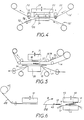
- the device shown partially, essentially comprises a fixed frame 20, a movable press 21, elements 22 for bringing between the fixed frame and the press a strip 16 'of transparent material intended to form the transparent protective window 16, and means for bringing a strip 15 ', intended to form the hot-melt film 15 in contact with the strip 16'.
- the press 21 is designed to pre-assemble the film 15 and the protective window 16. It is associated with the die 23 arranged to ensure the cutting of the protective window 16 and with heating members 24 arranged to ensure the heat sealing of this window and film 15. To cut the window 16, the elements 22 are movable vertically and stretch the strip 16 'against the cutting edge of the die. This pre-assembly being carried out, the complete positioning of the label on the piece of fabric is carried out on the device illustrated in more detail in FIG. 5. In practice, after the preassembly operation described above, the code is printed on the element used to support the mark, this element and the film 14 associated with the preassembled element 15 plus 16 are placed on the piece of fabric and the various components are fused using a heating press.
- the device illustrated in FIG. 5 comprises a fixed frame 20, a heating press 31 movable vertically in the direction of the double arrow A and means for bringing between the fixed frame and the press, on the one hand a strip 33 carrying the film 15 and the protective window 16 preassembled, on the other hand the marked element 12 and the lower film 14, and finally the fabric 11 and the film 17 intended to be deposited on the back of the strip of fabric, symmetrically with respect to the label affixed to the surface top of this fabric.
- a separating and guiding plate 34 is interposed between the fabric strip 11 and the lower film 14. Suitable drive rollers ensure the tension of the films as well as the drive of the piece of fabric.
- the hot-melt film 15 and the transparent protective window 16 instead of being pre-assembled, could also be supplied individually.
- the pre-assembly solution allows operations to be broken down, which makes it possible to provide two relatively simple stations instead of a single complicated station performing all the operations.
- the marked element 12 is brought into place by a transfer unit, not shown.
- Fig. 6 illustrates a preliminary phase of the method according to the invention during which a pocket 40 is formed using a hot-melt film 50 identical or similar to the two films of hot-melt substance 14 and 15, the marked element 12 being taken sandwiched between two layers of this film previously folded to form said pocket.
- the device comprises a stamp 41, a member 42 for supplying the device with hot-melt film 50 and transfer means (not shown) for bringing the marked element 12.
- a surface of this film 50 is cut to the shape and dimensions desired then folded around a point 43 on the element marked 12.
- This pocket 40 is then brought between a fixed frame 44 and a heat-sealing press 45 at the same time as the piece of fabric 11 and the lower film 17.
- the press 45 allows the various components to be fused permanently to the piece of fabric, providing the necessary heat and applying the required pressure.
- This procedure which consists of bonding two layers of the same hot-melt film 50 together ensures very good bonding and facilitates handling.
- the installation phase of the other components and in particular that of the window 16 can also be similar to that described with reference to FIG. 5.
- the most suitable printing technique is printing using dot matrix printers.
- dot matrix printers Several types are currently offered on the barcode market. The printers retained examples are those marketed under the names ZEBRA, M100L and BARPRINT 600.
- the reading material is intended to check the conformity of the printed code with the printed code at the request of the operator and to check the printing characteristics of the code.
- Bar code readers are for example marketed under the names DATALO-GIC, BARCODE, EBL, SANDWIK.
Landscapes
- Engineering & Computer Science (AREA)
- Textile Engineering (AREA)
- Physics & Mathematics (AREA)
- General Physics & Mathematics (AREA)
- Theoretical Computer Science (AREA)
- Chemical & Material Sciences (AREA)
- Materials Engineering (AREA)
- Treatment Of Fiber Materials (AREA)
- Labeling Devices (AREA)
Description
- La présente invention concerne un procédé de marquage d'une pièce de tissu, permettant le repérage de pièces de tissu, en particulier, l'identification de pièces telles que par exemple des blouses, des draps etc., au cours d'opérations de nettoyage, blanchisserie, teinturerie ou similaires et/ou le suivi de production dans une installation d'ennoblissement de ce tissu, dans lequel on fixe à au moins une des faces du tissu, au moins une étiquette portant un marquage. Un tel procédé est décrit dans le document EP-A-119 669.
- L'invention concerne également un dispositif pour la mise en oeuvre de ce procédé ainsi qu'une étiquette obtenue par ce procédé.
- L'ennoblissement des tissus, qu'il soit exécuté chez des façonniers ou dans des usines intégrées, est caractérisé par un nombre important de machines de production, destinées chacune à effectuer un traitement particulier sur les tissus et par une multitude d'articles en cours de traitement, simultanément présents dans les ateliers. De plus, les délais de fabrication imposés sont extrêmement serrés. Les entreprises se trouvent confrontées à plusieurs problèmes : d'une part le service d'ordonnancement et de lancement doit répartir les charges de travail entre les différentes machines, d'autre part les impératifs commerciaux sont tels qu'il faut pouvoir prévoir à tout moment la date de livraison des articles en cours de traitement et. éventuellement modifier l'ordonnancement pour accélérer la production de certaines commandes. Enfin, une connaissance plus précise des coûts de production nécessiterait de pouvoir identifier systématiquement les temps de passage de chaque tissu sur chaque machine. Simultanément la gestion de l'outil de production doit conserver une souplesse qui lui permet d'accepter de fréquentes modifications des circuits standards de fabrication. Toutes ces observations conduisent les industriels à chercher à mettre en place dans leurs usines des systèmes de suivi et de gestion de la production. Ces systèmes demandent en premier lieu de pouvoir disposer d'un moyen d'identification des articles en cours de traitement, au fur et à mesure de leur avance à travers les ateliers. Or, jusqu'à présent, cette identification était habituellement réalisée à l'aide de fiches qui suivaient les pièces mais n'étaient pas solidaires de celles-ci. La nécessité d'effectuer manuellement la lecture de la fiche et de transférer celle-ci entre l'entrée et la sortie de la machine de production pouvait être une source d'erreur ou d'oubli d'identification et constituer un frein réel à une grande automatisation de la production.
- Pour pallier ces inconvénients il a été proposé un système commercialisé sous la marque enregistrée ELSCAN consistant à marquer le tissu au moyen d'un code perforé et à prévoir des détecteurs pour détecter le code et des moyens informatiques pour analyser les données obtenues par le décodage du code par les détecteurs. Ce système de marquage ne donne pas satisfaction dans tous les cas.
- Par ailleurs, au cours du traitement de certaines pièces de tissu, par exemple au cours du nettoyage, de la teinture, de la désinfection, etc., de blouses de travail, de draps, ou similaires, dans des établissements spécialisés tels que des teintureries et blanchisseries industrielles, il est intéressant de pouvoir repérer lesdites pièces à tout moment, suivre leur cheminement à travers les installations et si nécessaire, intervenir sur ce cheminement. Actuellement, aucun moyen d'identification efficace permet un tel contrôle.
- La présente invention a pour but de pallier les inconvénients ci-dessus et combler les lacunes actuelles en proposant un procédé relativement simple et économique pour marquer une pièce de tissu de telle manière que la détection et le décodage des marques apposées sur les pièces permettent une connaissance des charges de travail aux différentes machines et aboutissent en conséquence à la bonne gestion d'un atelier de finissage. Dans ce but, le procédé selon l'invention est caractérisé en ce que l'on réalise l'étiquette en insérant un élément préalablement marqué entre deux films d'une substance thermofusible et en recouvrant le film supérieur d'une feuille transparente de protection réalisée en un matériau inerte aux traitements à subir par le tissu. b
- Selon une forme de réalisation particulièrement avantageuse, on découpe les deux films de substance thermofusible et la feuille transparente de protection de telle manière qu'ils débordent des côtés de l'élément marqué pour former une fenêtre de protection sur cet élément.
- L'étiquette est de préférence fixée sur le tissu par thermocollage sous pression. Dans ce but, la substance thermofusible des films a une température de fusion inférieure à celle de la feuille transparente de protection. Les films de substance thermofusible sont de préférence constitués par un copolyamide. La feuille transparente de protection est avantageusement constituée par une résine fluorocarbonée.
- La substance thermofusible des films a de préférence une température de fusion comprise entre 150 et 250 °C et de préférence au moins approximativement voisine de 180 °C.
- La feuille transparente de protection est avantageusement réalisée en un matériau dont la température de fusion est supérieure à 250 °C et de préférence au moins approximativement voisine de 350 °C.
- Selon un mode de réalisation particulièrement avantageux, l'étiquette est appliquée sur le tissu sous une pression approximativement voisine de 9 kg/cm2.
- Pour effectuer une protection maximale de l'étiquette, on fixe de préférence sous cette étiquette, au revers du tissu, un troisième film d'une substance thermofusible.
- Etant donné que la pièce de tissu peut subir différentes manipulations, et en particulier des retournements au cours des traitements d'ennoblissement, il peut être avantageux de marquer ce tissu sur ses deux faces. Dans ce but, l'on fixe symétriquement sur les deux faces du tissu deux étiquettes portant un marquage, chaque étiquette comportant un élément préalablement marqué, compris entre deux films d'une substance thermofusible, et dont le film supérieur est recouvert d'une feuille transparente de protection réalisée en un matériau inerte aux traitements à subir par le tissu.
- Le dispositif pour la mise en oeuvre du procédé est caractérisé en ce qu'il comporte des moyens pour marquer un élément, des moyens pour insérer cet élément préalablement marqué entre deux films d'une substance thermofusibie, des moyens pour recouvrir le film supérieur d'une feuille transparente de production d'un matériau inerte aux traitements à subir par le tissu, et des moyens pour appliquer ces différents composants dans un ordre prédéterminé à la surface du tissu.
- Selon un mode de réalisation préféré, lesdits moyens pour marquer l'élément comportent un organe pour imprimer sur cet élément un code à barres, la direction des barres étant parallèle à l'axe du tissu.
- Selon un autre mode de réalisation, lesdits moyens pour marquer l'élément comportent un organe pour imprimer sur cet élément un code à barres, la direction des barres étant inclinée par rapport à l'axe du tissu.
- Selon un autre aspect de la présente invention, les moyens pour insérer l'élément entre les deux films et les moyens pour recouvrir le film supérieur de la feuille transparente de protection comportent des mécanismes d'approvisionnement simultanément des films et de la feuille transparente en bandes, et des moyens pour découper les surfaces déterminées de ces matériaux dans ces bandes.
- Les moyens pour appliquer les différents composants à la surface du tissu comportent avantageusement une presse pour soumettre ces composants à une pression déterminée et des organes chauffants pour porter la température des films à une valeur au moins égale à leur température de fusion.
- La présente invention concerne enfin une étiquette obtenue par le procédé défini ci-dessus, et caractérisée en ce qu'elle comporte au moins un élément destiné à porter un marquage, deux films d'un matériau thermofusible disposés de part et d'autre de cet élément, et une fenêtre de protection réalisée au moyen d'une feuille d'un matériau transparent appliquée sur le film supérieur.
- La présente invention, ses principaux avantages et ses caractéristiques essentielles, seront mieux compris en référence à la description d'un exemple de réalisation et du dessin annexé dans lequel :
- La figure 1 représente une vue en plan d'une étiquette selon l'invention,
- La figure 2 représente une vue en coupe éclatée de l'étiquette de la fig. 1,
- La figure 3 représente une pièce de tissu qui a été marquée au moyen de l'étiquette des figures 1 et 2,
- La figure 4 représente une vue schématique d'une première partie du dispositif illustrant un premier mode de mise en oeuvre du procédé selon l'invention,
- La figure 5 représente une vue schématique d'une seconde partie du dispositif de la fig. 1, et
- La figure 6 représente une vue schématique illustrant une seconde forme de réalisation du procédé de l'invention.
- En référence aux figures 1 à 3, l'étiquette 10 représentée, fixée sur au moins une face d'une pièce de tissu 11 se compose essentiellement d'un élément 12 préalablement marqué au moyen d'un code à barres 13, pris entre deux films 14 et 15 d'une substance thermofusible, et recouverte, à sa surface supérieure par une feuille transparente 16 d'un matériau inerte aux traitements à subir par le tissu.
- Le code 13 utilisé est un code à barres noires sur fond blanc. Le système utilisé est de préférence conçu de telle manière que l'opérateur puisse choisir parmi deux épaisseurs de barres et parmi deux espaces. Pour les barres larges les épaisseurs sont par exemple de 1,18 mm ou de 2,36 mm ; les barres minces ont dans ce cas respectivement les épaisseurs suivantes 0,45 et 0,90 mm ; les espaces sont de 0,46 et de 0,92 mm.
- Le code à barres doit également comporter un signe de contrôle. Le message à coder peut être alphanumérique et peut comporter un nombre indéterminé de caractères. Ce nombre est avantageusement limité à 11 caractères. La hauteur des barres est de préférence choisie par l'opérateur, par exemple entre 20 et 55 mm.
- La matière utilisée pour réaliser l'élément marqué est avantageusement du papier ou du non- tissé, éventuellement enduit sur une face. La largeur peut être de 80 mm et sa longueur de l'ordre de 180 mm.
- Les deux films en substance thermofusible 14 et 15 sont de préférence en copolyamide dont la température de fusion est comprise entre 150 et 250 °C et avantageusement voisine de 180°C. Comme le montre la fig. 2 un troisième film 17 identique aux films 14 et 15, peut être disposé sur la face inférieure de la pièce de tissu 11.
- La feuille transparente de protection 16 est de préférence réalisée au moyen d'une résine fluorocarbonée fixée par thermocollage sur la face supérieure du film 15. Cette résine fluorocarbonée a avantageusement une température de fusion supérieure à 250 °C et de préférence au moins approximativement voisine de 350 °C.
- Comme mentionné précédemment, il peut être avantageux dans certains cas de prévoir un marquage symétrique sur les deux faces du tissu consistant à apposer deux étiquettes identiques respectivement sur les deux surfaces d'une même pièce de tissu.
- Comme le montre la fig. 3, la position de l'étiquette 10 sur la pièce de tissu 11 s'effectue d'une manière déterminée par l'opérateur à une distance d de l'extrémité de la pièce dans le sens axial. Le centre de l'étiquette se trouve à une distance e de l'axe du tissu. Le centrage est déterminé avec une précision imposée au système.
- Avec les matériaux utilisés, le thermocollage sur le tissu est de préférence effectué dans les conditions suivantes :
- - la température est réglée entre 180 et 220 °C avec une tolérance de l'ordre de ± 5 °C sur toute la surface de chauffe.
- - une pression uniforme est appliquée sur toute la surface des films, cette pression étant réglable entre 6 et 12 kg/cm2.
- - la durée de maintien de la pression et de la température s'étale entre 5 et 15 secondes. Les réglages ou ajustages sont indiqués par l'opérateur selon les types de tissu sur lesquels est fixée l'étiquette 10.
- L'utilisation d'un code à barres permet un contrôle aisé du marquage à l'aide d'un détecteur ou lecteur de code à barres connu qui permet de vérifier d'une part que le code lu est identique à celui introduit par un clavier agencé pour imprimer le code à barres et d'autre part que le rapport de contraste, c'est-à-dire le contraste entre les zones noires et les zones blanches est supérieur à une valeur préaffichée entre 0,7 et 1.
- Différents modes de mises en oeuvre du procédé de marquage défini ci-dessus peuvent être utilisés. Un point essentiel du système de marquage est la nécessité d'obtenir après thermocollage une adhérence parfaite entre les différents constituants de la marque c'est-à-dire entre l'élément marqué, les films, le tissu et la fenêtre de protection. En particulier, il faut obtenir une absence totale de plis sur les films ou sur l'élément marqué. Cet objectif est rendu plus difficile à atteindre du fait de la disposition relative à respecter pour les différents films.
- Selon le mode de réalisation illustré par la fig. 4, le dispositif, représenté partiellement, comporte essentiellement un bâti fixe 20, une presse mobile 21, des éléments 22 pour amener entre le bâti fixe et la presse une bande 16' de matière transparente destinée à former la fenêtre transparente de protection 16, et des moyens pour amener une bande 15', destinée à former le film thermofusible 15 en contact avec la bande 16'.
- La presse 21 est conçue pour assurer le préassemblage du film 15 et de la fenêtre de protection 16. Elle est associée à la matrice 23 agencée pour assurer la découpe de la fenêtre de protection 16 et à des organes chauffants 24 agencés pour assurer le thermocollage de cette fenêtre et du film 15. Pour assurer la découpe de la fenêtre 16, les éléments 22 sont mobiles verticalement et tendent la bande 16' contre l'arête coupante de la matrice. Ce préassemblage étant effectué, la mise en place complète de l'étiquette sur la pièce de tissu est effectuée sur le dispositif illustré plus en détail par la fig. 5. Dans la pratique, après l'opération de préassemblage décrite ci-dessus, on imprime le code sur l'élément servant de support à la marque, on place cet élément et le film 14 associé à l'élément préassemblé 15 plus 16 sur la pièce de tissu et on effectue le thermocollage des différents composants au moyen d'une presse chauffante.
- A cet effet, le dispositif illustré par la fig. 5 comporte un bâti fixe 20, une presse chauffante 31 mobile verticalement dans le sens de la double flèche A et des moyens pour amener entre le bâti fixe et la presse, d'une part une bande 33 portant le film 15 et la fenêtre de protection 16 préassemblés, d'autre part l'élément marqué 12 et le film inférieur 14, et enfin le tissu 11 et le film 17 destiné à être déposé au revers de la bande de tissu, symétriquement par rapport à l'étiquette apposée sur la surface supérieure de ce tissu. Une plaque 34 de séparation et de guidage est interposée entre la bande de tissu 11 et le film inférieur 14. Des rouleaux d'entraînement appropriés assurent la tension des films ainsi que l'entraînement de la pièce de tissu.
- Il est évident que le film thermofusible 15 et la fenêtre transparente de protection 16, au lieu d'être préassemblés, pourraient également être amenés individuellement. La solution du préassemblage permet de décomposer les opérations, ce qui permet de prévoir deux stations relativement simples au lieu d'une seule station compliquée effectuant toutes les opérations.
- L'élément marqué 12 est amené en place par une unité de transfert non représentée.
- La fig. 6 illustre une phase préliminaire du procédé selon l'invention au cours de laquelle on forme une poche 40 à l'aide d'un film thermofusible 50 identique ou similaire aux deux films de substance thermofusible 14 et 15, l'élément marqué 12 étant pris en sandwich entre deux couches de ce film préalablement replié pour former ladite poche. Le dispositif comporte une étampe 41, un organe 42 d'alimentation du dispositif en film thermofusible 50 et des moyens de transfert (non représentés) pour amener l'élément marqué 12. Une surface de ce film 50 est découpée à la forme et aux dimensions voulues puis repliée autour d'un point 43 sur l'élément marqué 12. Cette poche 40 est ensuite amenée entre un bâti fixe 44 et une presse de thermocollage 45 en même temps que la pièce de tissu 11 et le film inférieur 17. La presse 45 permet de thermocoller définitivement les différents composants sur la pièce de tissu en apportant la chaleur nécessaire et en appliquant la pression requise.
- Cette manière de procéder qui consiste à coller ensemble deux couches d'un même film thermofusible 50 assure une très bonne liaison et facilite la manipulation. La phase de mise en place des autres composants et notamment celle de la fenêtre 16 peut également être similaire à celle décrite en référence à la fig. 5.
- Compte tenu du support utilisé, la technique d'impression la mieux adaptée est l'impression à l'aide d'imprimantes matricielles. Plusieurs types sont actuellement proposés sur le marché du code à barres. Les imprimantes retenues à titre d'exemples sont celles commercialisées sous les dénominations ZEBRA, M100L et BARPRINT 600.
- Le matériel de lecture est destiné à vérifier la conformité du code imprimé avec le code imprimé à la demande de l'opérateur et à vérifier les caractéristiques d'impression du code. Des lecteurs de codes à barres sont par exemple commercialisés sous les dénominations DATALO-GIC, BARCODE, EBL, SANDWIK.
- La présente invention n'est pas limitée aux formes de réalisation décrites mais peut subir différentes modifications et se présenter sous diverses variantes pour l'homme de l'art.
Claims (17)
Priority Applications (1)
| Application Number | Priority Date | Filing Date | Title |
|---|---|---|---|
| AT86440032T ATE44325T1 (de) | 1985-04-30 | 1986-04-30 | Kennzeichen eines textilstuecks, vorrichtung zur durchfuehrung dieses verfahrens und so erhaltenes etikett. |
Applications Claiming Priority (2)
| Application Number | Priority Date | Filing Date | Title |
|---|---|---|---|
| FR8506703 | 1985-04-30 | ||
| FR8506703A FR2581093B1 (fr) | 1985-04-30 | 1985-04-30 | Marquage d'une piece de tissu, dispositif pour la mise en oeuvre de ce procede et etiquette obtenue |
Publications (2)
| Publication Number | Publication Date |
|---|---|
| EP0201440A1 EP0201440A1 (fr) | 1986-11-12 |
| EP0201440B1 true EP0201440B1 (fr) | 1989-06-28 |
Family
ID=9318905
Family Applications (1)
| Application Number | Title | Priority Date | Filing Date |
|---|---|---|---|
| EP86440032A Expired EP0201440B1 (fr) | 1985-04-30 | 1986-04-30 | Marquage d'une pièce de tissu, dispositif pour la mise en oeuvre de ce procédé et étiquette obtenue |
Country Status (4)
| Country | Link |
|---|---|
| EP (1) | EP0201440B1 (fr) |
| AT (1) | ATE44325T1 (fr) |
| DE (1) | DE3664171D1 (fr) |
| FR (1) | FR2581093B1 (fr) |
Cited By (2)
| Publication number | Priority date | Publication date | Assignee | Title |
|---|---|---|---|---|
| EP0489960A1 (fr) * | 1990-12-13 | 1992-06-17 | SCHREINER ETIKETTEN UND SELBSTKLEBETECHNIK GMBH & CO. | Procédé pour la fabrication d'étiquettes thermosoudables et étiquette obtenue par ce procédé |
| FR2811205A1 (fr) * | 2000-07-06 | 2002-01-11 | Georges Lucien Altounian | Procede d'assemblage de pieces de textiles et pieces de textiles composites obtenues par ce procede |
Families Citing this family (5)
| Publication number | Priority date | Publication date | Assignee | Title |
|---|---|---|---|---|
| DE3707344A1 (de) * | 1987-03-07 | 1988-09-15 | Giselher Valk & Partner Gmbh P | Verfahren zur stueck- und/oder partieidentifizierung und -lokalisierung sowie datentraeger und datenerfassungseinrichtung zur durchfuehrung des verfahrens |
| DE3833789A1 (de) * | 1988-10-05 | 1990-04-12 | Kuesters Prozesstechnik Gmbh | Etikett zur identifizierung eines stuecks aus textilem oder aehnlichem material |
| FR2839347A1 (fr) * | 2002-05-02 | 2003-11-07 | Marc Sistach | Procede pour pouvoir solidariser des matieres differentes entre elles |
| FR2865113B1 (fr) * | 2004-01-20 | 2006-02-17 | Salomon Sa | Renfort |
| DE102018006211B4 (de) | 2018-08-07 | 2025-03-13 | Bundesdruckerei Gmbh | Verfahren zum Protokollieren von Erkennungsmerkmalen für Erzeugnisse |
Family Cites Families (4)
| Publication number | Priority date | Publication date | Assignee | Title |
|---|---|---|---|---|
| GB1215007A (en) * | 1967-03-08 | 1970-12-09 | Polymark Int Ltd | Heat-sealable devices for marking articles |
| DE2507642A1 (de) * | 1975-02-19 | 1976-09-02 | Ludwig Hager | Verfahren zum aufbringen von abzeichen und beschriftungen o.dgl. auf textilmaterialien |
| FR2501397A1 (fr) * | 1981-03-06 | 1982-09-10 | Seprosy | Manchon en matiere synthetique pour le marquage de recipients |
| NL8301024A (nl) * | 1983-03-22 | 1984-10-16 | K En N Laundry Computer System | Werkwijze en inrichting voor het etiketteren van voorwerpen. |
-
1985
- 1985-04-30 FR FR8506703A patent/FR2581093B1/fr not_active Expired
-
1986
- 1986-04-30 AT AT86440032T patent/ATE44325T1/de not_active IP Right Cessation
- 1986-04-30 DE DE8686440032T patent/DE3664171D1/de not_active Expired
- 1986-04-30 EP EP86440032A patent/EP0201440B1/fr not_active Expired
Cited By (2)
| Publication number | Priority date | Publication date | Assignee | Title |
|---|---|---|---|---|
| EP0489960A1 (fr) * | 1990-12-13 | 1992-06-17 | SCHREINER ETIKETTEN UND SELBSTKLEBETECHNIK GMBH & CO. | Procédé pour la fabrication d'étiquettes thermosoudables et étiquette obtenue par ce procédé |
| FR2811205A1 (fr) * | 2000-07-06 | 2002-01-11 | Georges Lucien Altounian | Procede d'assemblage de pieces de textiles et pieces de textiles composites obtenues par ce procede |
Also Published As
| Publication number | Publication date |
|---|---|
| EP0201440A1 (fr) | 1986-11-12 |
| FR2581093B1 (fr) | 1988-06-10 |
| FR2581093A1 (fr) | 1986-10-31 |
| DE3664171D1 (en) | 1989-08-03 |
| ATE44325T1 (de) | 1989-07-15 |
Similar Documents
| Publication | Publication Date | Title |
|---|---|---|
| US5421933A (en) | System for producing labels from a web | |
| EP0201440B1 (fr) | Marquage d'une pièce de tissu, dispositif pour la mise en oeuvre de ce procédé et étiquette obtenue | |
| US20070289703A1 (en) | Thermal transfer media and method of making and using same | |
| US9535028B2 (en) | Biosensors and methods of preparing same | |
| FR2475495A1 (fr) | Appareil de commande d'impression d'etiquettes, etiquettes et procede de commande d'un tel appareil | |
| CA2282667A1 (fr) | Procede et systeme d'emission d'etiquettes d'identification | |
| JPH0444941A (ja) | 自動ラベル貼付装置 | |
| CA2129068A1 (fr) | Systeme d'impression pour etiquettes non doublees | |
| EP0706150A1 (fr) | Procédé de personnalisation en série de cartes | |
| EP0625466B1 (fr) | Dispositif d'application d'images dans une machine d'impression de sécurité | |
| US3575755A (en) | Code dating with heat shrinkable and pressure features | |
| FR2465277A1 (fr) | Barrette magnetique pour documents, procede d'application et documents munis d'une telle barrette | |
| US20090302115A1 (en) | Bar Code Obliteration System and Method | |
| EP0249526A1 (fr) | Machine pour la plastification d'un élément de forme plate par application et fusion d'un film en matière thermo-plastique | |
| CA2463605A1 (fr) | Document de securite a couches multiples et procede permettant de le produire | |
| JPH01292313A (ja) | セルの割断装置および割断方法 | |
| CA2367495A1 (fr) | Tri par taille de gants jetables | |
| DE59009648D1 (de) | Verfahren zum Aufbringen und Versiegeln von Informationen auf kartenförmigen Informationsträgern und danach hergestellte Karte. | |
| EP1147018B1 (fr) | Procede et installation de fabrication de coupons personnalises | |
| DE69409822T2 (de) | Vorrichtung und verfahren zum etikettieren von behältern unter verwendung heissverschweissbarer etiketten | |
| WO2002101147A1 (fr) | Fil de securite ou film de transfert pour marquage a chaud pour billets de banque, documents ou autres articles a securiser | |
| GB2032343A (en) | Preparing webs of material containing a row of pockets | |
| KR20020019092A (ko) | 광학적으로 판독 가능한 데이터 캐리어 코팅 장치 및 방법 | |
| EP0710060A1 (fr) | Procédé de fabrication pour support plastique, dispositif de fabrication pour un tel support et utilisation du procédé pour la fabrication de cartes à circuits integrés | |
| JP2741440B2 (ja) | バーコード印刷方法 |
Legal Events
| Date | Code | Title | Description |
|---|---|---|---|
| PUAI | Public reference made under article 153(3) epc to a published international application that has entered the european phase |
Free format text: ORIGINAL CODE: 0009012 |
|
| AK | Designated contracting states |
Kind code of ref document: A1 Designated state(s): AT BE CH DE FR GB IT LI LU NL SE |
|
| 17P | Request for examination filed |
Effective date: 19870205 |
|
| 17Q | First examination report despatched |
Effective date: 19880921 |
|
| GRAA | (expected) grant |
Free format text: ORIGINAL CODE: 0009210 |
|
| AK | Designated contracting states |
Kind code of ref document: B1 Designated state(s): AT BE CH DE FR GB IT LI LU NL SE |
|
| PG25 | Lapsed in a contracting state [announced via postgrant information from national office to epo] |
Ref country code: NL Effective date: 19890628 Ref country code: IT Free format text: LAPSE BECAUSE OF FAILURE TO SUBMIT A TRANSLATION OF THE DESCRIPTION OR TO PAY THE FEE WITHIN THE PRE;WARNING: LAPSES OF ITALIAN PATENTS WITH EFFECTIVE DATE BEFORE 2007 MAY HAVE OCCURRED AT ANY TIME BEFORE 2007. THE CORRECT EFFECTIVE DATE MAY BE DIFFERENT FROM THE ONE RECORDED.SCRIBED TIME-LIMIT Effective date: 19890628 Ref country code: AT Effective date: 19890628 Ref country code: GB Effective date: 19890628 Ref country code: SE Effective date: 19890628 |
|
| REF | Corresponds to: |
Ref document number: 44325 Country of ref document: AT Date of ref document: 19890715 Kind code of ref document: T |
|
| REF | Corresponds to: |
Ref document number: 3664171 Country of ref document: DE Date of ref document: 19890803 |
|
| NLV1 | Nl: lapsed or annulled due to failure to fulfill the requirements of art. 29p and 29m of the patents act | ||
| GBV | Gb: ep patent (uk) treated as always having been void in accordance with gb section 77(7)/1977 [no translation filed] | ||
| PLBE | No opposition filed within time limit |
Free format text: ORIGINAL CODE: 0009261 |
|
| STAA | Information on the status of an ep patent application or granted ep patent |
Free format text: STATUS: NO OPPOSITION FILED WITHIN TIME LIMIT |
|
| PG25 | Lapsed in a contracting state [announced via postgrant information from national office to epo] |
Ref country code: LU Free format text: LAPSE BECAUSE OF NON-PAYMENT OF DUE FEES Effective date: 19900430 Ref country code: CH Effective date: 19900430 Ref country code: BE Effective date: 19900430 Ref country code: LI Effective date: 19900430 |
|
| 26N | No opposition filed | ||
| BERE | Be: lapsed |
Owner name: CERMAT Effective date: 19900430 |
|
| PG25 | Lapsed in a contracting state [announced via postgrant information from national office to epo] |
Ref country code: FR Effective date: 19901228 |
|
| REG | Reference to a national code |
Ref country code: CH Ref legal event code: PL |
|
| PG25 | Lapsed in a contracting state [announced via postgrant information from national office to epo] |
Ref country code: DE Effective date: 19910101 |
|
| REG | Reference to a national code |
Ref country code: FR Ref legal event code: ST |