EP0201442A2 - Dispositif de prothèse modulaire - Google Patents
Dispositif de prothèse modulaire Download PDFInfo
- Publication number
- EP0201442A2 EP0201442A2 EP86460004A EP86460004A EP0201442A2 EP 0201442 A2 EP0201442 A2 EP 0201442A2 EP 86460004 A EP86460004 A EP 86460004A EP 86460004 A EP86460004 A EP 86460004A EP 0201442 A2 EP0201442 A2 EP 0201442A2
- Authority
- EP
- European Patent Office
- Prior art keywords
- prosthesis
- bars
- groove
- width
- bar
- Prior art date
- Legal status (The legal status is an assumption and is not a legal conclusion. Google has not performed a legal analysis and makes no representation as to the accuracy of the status listed.)
- Granted
Links
Images

Classifications
-
- A—HUMAN NECESSITIES
- A61—MEDICAL OR VETERINARY SCIENCE; HYGIENE
- A61F—FILTERS IMPLANTABLE INTO BLOOD VESSELS; PROSTHESES; DEVICES PROVIDING PATENCY TO, OR PREVENTING COLLAPSING OF, TUBULAR STRUCTURES OF THE BODY, e.g. STENTS; ORTHOPAEDIC, NURSING OR CONTRACEPTIVE DEVICES; FOMENTATION; TREATMENT OR PROTECTION OF EYES OR EARS; BANDAGES, DRESSINGS OR ABSORBENT PADS; FIRST-AID KITS
- A61F2/00—Filters implantable into blood vessels; Prostheses, i.e. artificial substitutes or replacements for parts of the body; Appliances for connecting them with the body; Devices providing patency to, or preventing collapsing of, tubular structures of the body, e.g. stents
- A61F2/02—Prostheses implantable into the body
- A61F2/30—Joints
- A61F2/32—Joints for the hip
- A61F2/36—Femoral heads ; Femoral endoprostheses
- A61F2/3662—Femoral shafts
-
- A—HUMAN NECESSITIES
- A61—MEDICAL OR VETERINARY SCIENCE; HYGIENE
- A61F—FILTERS IMPLANTABLE INTO BLOOD VESSELS; PROSTHESES; DEVICES PROVIDING PATENCY TO, OR PREVENTING COLLAPSING OF, TUBULAR STRUCTURES OF THE BODY, e.g. STENTS; ORTHOPAEDIC, NURSING OR CONTRACEPTIVE DEVICES; FOMENTATION; TREATMENT OR PROTECTION OF EYES OR EARS; BANDAGES, DRESSINGS OR ABSORBENT PADS; FIRST-AID KITS
- A61F2/00—Filters implantable into blood vessels; Prostheses, i.e. artificial substitutes or replacements for parts of the body; Appliances for connecting them with the body; Devices providing patency to, or preventing collapsing of, tubular structures of the body, e.g. stents
- A61F2/02—Prostheses implantable into the body
- A61F2/30—Joints
- A61F2/30721—Accessories
- A61F2/30734—Modular inserts, sleeves or augments, e.g. placed on proximal part of stem for fixation purposes or wedges for bridging a bone defect
-
- A—HUMAN NECESSITIES
- A61—MEDICAL OR VETERINARY SCIENCE; HYGIENE
- A61F—FILTERS IMPLANTABLE INTO BLOOD VESSELS; PROSTHESES; DEVICES PROVIDING PATENCY TO, OR PREVENTING COLLAPSING OF, TUBULAR STRUCTURES OF THE BODY, e.g. STENTS; ORTHOPAEDIC, NURSING OR CONTRACEPTIVE DEVICES; FOMENTATION; TREATMENT OR PROTECTION OF EYES OR EARS; BANDAGES, DRESSINGS OR ABSORBENT PADS; FIRST-AID KITS
- A61F2/00—Filters implantable into blood vessels; Prostheses, i.e. artificial substitutes or replacements for parts of the body; Appliances for connecting them with the body; Devices providing patency to, or preventing collapsing of, tubular structures of the body, e.g. stents
- A61F2/02—Prostheses implantable into the body
- A61F2/30—Joints
- A61F2002/30001—Additional features of subject-matter classified in A61F2/28, A61F2/30 and subgroups thereof
- A61F2002/30108—Shapes
- A61F2002/3011—Cross-sections or two-dimensional shapes
- A61F2002/30112—Rounded shapes, e.g. with rounded corners
-
- A—HUMAN NECESSITIES
- A61—MEDICAL OR VETERINARY SCIENCE; HYGIENE
- A61F—FILTERS IMPLANTABLE INTO BLOOD VESSELS; PROSTHESES; DEVICES PROVIDING PATENCY TO, OR PREVENTING COLLAPSING OF, TUBULAR STRUCTURES OF THE BODY, e.g. STENTS; ORTHOPAEDIC, NURSING OR CONTRACEPTIVE DEVICES; FOMENTATION; TREATMENT OR PROTECTION OF EYES OR EARS; BANDAGES, DRESSINGS OR ABSORBENT PADS; FIRST-AID KITS
- A61F2/00—Filters implantable into blood vessels; Prostheses, i.e. artificial substitutes or replacements for parts of the body; Appliances for connecting them with the body; Devices providing patency to, or preventing collapsing of, tubular structures of the body, e.g. stents
- A61F2/02—Prostheses implantable into the body
- A61F2/30—Joints
- A61F2002/30001—Additional features of subject-matter classified in A61F2/28, A61F2/30 and subgroups thereof
- A61F2002/30108—Shapes
- A61F2002/3011—Cross-sections or two-dimensional shapes
- A61F2002/30138—Convex polygonal shapes
- A61F2002/30153—Convex polygonal shapes rectangular
-
- A—HUMAN NECESSITIES
- A61—MEDICAL OR VETERINARY SCIENCE; HYGIENE
- A61F—FILTERS IMPLANTABLE INTO BLOOD VESSELS; PROSTHESES; DEVICES PROVIDING PATENCY TO, OR PREVENTING COLLAPSING OF, TUBULAR STRUCTURES OF THE BODY, e.g. STENTS; ORTHOPAEDIC, NURSING OR CONTRACEPTIVE DEVICES; FOMENTATION; TREATMENT OR PROTECTION OF EYES OR EARS; BANDAGES, DRESSINGS OR ABSORBENT PADS; FIRST-AID KITS
- A61F2/00—Filters implantable into blood vessels; Prostheses, i.e. artificial substitutes or replacements for parts of the body; Appliances for connecting them with the body; Devices providing patency to, or preventing collapsing of, tubular structures of the body, e.g. stents
- A61F2/02—Prostheses implantable into the body
- A61F2/30—Joints
- A61F2002/30001—Additional features of subject-matter classified in A61F2/28, A61F2/30 and subgroups thereof
- A61F2002/30316—The prosthesis having different structural features at different locations within the same prosthesis; Connections between prosthetic parts; Special structural features of bone or joint prostheses not otherwise provided for
- A61F2002/30317—The prosthesis having different structural features at different locations within the same prosthesis
- A61F2002/30324—The prosthesis having different structural features at different locations within the same prosthesis differing in thickness
-
- A—HUMAN NECESSITIES
- A61—MEDICAL OR VETERINARY SCIENCE; HYGIENE
- A61F—FILTERS IMPLANTABLE INTO BLOOD VESSELS; PROSTHESES; DEVICES PROVIDING PATENCY TO, OR PREVENTING COLLAPSING OF, TUBULAR STRUCTURES OF THE BODY, e.g. STENTS; ORTHOPAEDIC, NURSING OR CONTRACEPTIVE DEVICES; FOMENTATION; TREATMENT OR PROTECTION OF EYES OR EARS; BANDAGES, DRESSINGS OR ABSORBENT PADS; FIRST-AID KITS
- A61F2/00—Filters implantable into blood vessels; Prostheses, i.e. artificial substitutes or replacements for parts of the body; Appliances for connecting them with the body; Devices providing patency to, or preventing collapsing of, tubular structures of the body, e.g. stents
- A61F2/02—Prostheses implantable into the body
- A61F2/30—Joints
- A61F2002/30001—Additional features of subject-matter classified in A61F2/28, A61F2/30 and subgroups thereof
- A61F2002/30316—The prosthesis having different structural features at different locations within the same prosthesis; Connections between prosthetic parts; Special structural features of bone or joint prostheses not otherwise provided for
- A61F2002/30329—Connections or couplings between prosthetic parts, e.g. between modular parts; Connecting elements
- A61F2002/30383—Connections or couplings between prosthetic parts, e.g. between modular parts; Connecting elements made by laterally inserting a protrusion, e.g. a rib into a complementarily-shaped groove
- A61F2002/30387—Dovetail connection
-
- A—HUMAN NECESSITIES
- A61—MEDICAL OR VETERINARY SCIENCE; HYGIENE
- A61F—FILTERS IMPLANTABLE INTO BLOOD VESSELS; PROSTHESES; DEVICES PROVIDING PATENCY TO, OR PREVENTING COLLAPSING OF, TUBULAR STRUCTURES OF THE BODY, e.g. STENTS; ORTHOPAEDIC, NURSING OR CONTRACEPTIVE DEVICES; FOMENTATION; TREATMENT OR PROTECTION OF EYES OR EARS; BANDAGES, DRESSINGS OR ABSORBENT PADS; FIRST-AID KITS
- A61F2/00—Filters implantable into blood vessels; Prostheses, i.e. artificial substitutes or replacements for parts of the body; Appliances for connecting them with the body; Devices providing patency to, or preventing collapsing of, tubular structures of the body, e.g. stents
- A61F2/02—Prostheses implantable into the body
- A61F2/30—Joints
- A61F2002/30001—Additional features of subject-matter classified in A61F2/28, A61F2/30 and subgroups thereof
- A61F2002/30316—The prosthesis having different structural features at different locations within the same prosthesis; Connections between prosthetic parts; Special structural features of bone or joint prostheses not otherwise provided for
- A61F2002/30535—Special structural features of bone or joint prostheses not otherwise provided for
- A61F2002/30604—Special structural features of bone or joint prostheses not otherwise provided for modular
-
- A—HUMAN NECESSITIES
- A61—MEDICAL OR VETERINARY SCIENCE; HYGIENE
- A61F—FILTERS IMPLANTABLE INTO BLOOD VESSELS; PROSTHESES; DEVICES PROVIDING PATENCY TO, OR PREVENTING COLLAPSING OF, TUBULAR STRUCTURES OF THE BODY, e.g. STENTS; ORTHOPAEDIC, NURSING OR CONTRACEPTIVE DEVICES; FOMENTATION; TREATMENT OR PROTECTION OF EYES OR EARS; BANDAGES, DRESSINGS OR ABSORBENT PADS; FIRST-AID KITS
- A61F2/00—Filters implantable into blood vessels; Prostheses, i.e. artificial substitutes or replacements for parts of the body; Appliances for connecting them with the body; Devices providing patency to, or preventing collapsing of, tubular structures of the body, e.g. stents
- A61F2/02—Prostheses implantable into the body
- A61F2/30—Joints
- A61F2002/30001—Additional features of subject-matter classified in A61F2/28, A61F2/30 and subgroups thereof
- A61F2002/30316—The prosthesis having different structural features at different locations within the same prosthesis; Connections between prosthetic parts; Special structural features of bone or joint prostheses not otherwise provided for
- A61F2002/30535—Special structural features of bone or joint prostheses not otherwise provided for
- A61F2002/30604—Special structural features of bone or joint prostheses not otherwise provided for modular
- A61F2002/30616—Sets comprising a plurality of prosthetic parts of different sizes or orientations
-
- A—HUMAN NECESSITIES
- A61—MEDICAL OR VETERINARY SCIENCE; HYGIENE
- A61F—FILTERS IMPLANTABLE INTO BLOOD VESSELS; PROSTHESES; DEVICES PROVIDING PATENCY TO, OR PREVENTING COLLAPSING OF, TUBULAR STRUCTURES OF THE BODY, e.g. STENTS; ORTHOPAEDIC, NURSING OR CONTRACEPTIVE DEVICES; FOMENTATION; TREATMENT OR PROTECTION OF EYES OR EARS; BANDAGES, DRESSINGS OR ABSORBENT PADS; FIRST-AID KITS
- A61F2/00—Filters implantable into blood vessels; Prostheses, i.e. artificial substitutes or replacements for parts of the body; Appliances for connecting them with the body; Devices providing patency to, or preventing collapsing of, tubular structures of the body, e.g. stents
- A61F2/02—Prostheses implantable into the body
- A61F2/30—Joints
- A61F2/32—Joints for the hip
- A61F2/36—Femoral heads ; Femoral endoprostheses
- A61F2/3609—Femoral heads or necks; Connections of endoprosthetic heads or necks to endoprosthetic femoral shafts
- A61F2002/3625—Necks
- A61F2002/3631—Necks with an integral complete or partial peripheral collar or bearing shoulder at its base
-
- A—HUMAN NECESSITIES
- A61—MEDICAL OR VETERINARY SCIENCE; HYGIENE
- A61F—FILTERS IMPLANTABLE INTO BLOOD VESSELS; PROSTHESES; DEVICES PROVIDING PATENCY TO, OR PREVENTING COLLAPSING OF, TUBULAR STRUCTURES OF THE BODY, e.g. STENTS; ORTHOPAEDIC, NURSING OR CONTRACEPTIVE DEVICES; FOMENTATION; TREATMENT OR PROTECTION OF EYES OR EARS; BANDAGES, DRESSINGS OR ABSORBENT PADS; FIRST-AID KITS
- A61F2220/00—Fixations or connections for prostheses classified in groups A61F2/00 - A61F2/26 or A61F2/82 or A61F9/00 or A61F11/00 or subgroups thereof
- A61F2220/0025—Connections or couplings between prosthetic parts, e.g. between modular parts; Connecting elements
-
- A—HUMAN NECESSITIES
- A61—MEDICAL OR VETERINARY SCIENCE; HYGIENE
- A61F—FILTERS IMPLANTABLE INTO BLOOD VESSELS; PROSTHESES; DEVICES PROVIDING PATENCY TO, OR PREVENTING COLLAPSING OF, TUBULAR STRUCTURES OF THE BODY, e.g. STENTS; ORTHOPAEDIC, NURSING OR CONTRACEPTIVE DEVICES; FOMENTATION; TREATMENT OR PROTECTION OF EYES OR EARS; BANDAGES, DRESSINGS OR ABSORBENT PADS; FIRST-AID KITS
- A61F2230/00—Geometry of prostheses classified in groups A61F2/00 - A61F2/26 or A61F2/82 or A61F9/00 or A61F11/00 or subgroups thereof
- A61F2230/0002—Two-dimensional shapes, e.g. cross-sections
- A61F2230/0004—Rounded shapes, e.g. with rounded corners
-
- A—HUMAN NECESSITIES
- A61—MEDICAL OR VETERINARY SCIENCE; HYGIENE
- A61F—FILTERS IMPLANTABLE INTO BLOOD VESSELS; PROSTHESES; DEVICES PROVIDING PATENCY TO, OR PREVENTING COLLAPSING OF, TUBULAR STRUCTURES OF THE BODY, e.g. STENTS; ORTHOPAEDIC, NURSING OR CONTRACEPTIVE DEVICES; FOMENTATION; TREATMENT OR PROTECTION OF EYES OR EARS; BANDAGES, DRESSINGS OR ABSORBENT PADS; FIRST-AID KITS
- A61F2230/00—Geometry of prostheses classified in groups A61F2/00 - A61F2/26 or A61F2/82 or A61F9/00 or A61F11/00 or subgroups thereof
- A61F2230/0002—Two-dimensional shapes, e.g. cross-sections
- A61F2230/0017—Angular shapes
- A61F2230/0019—Angular shapes rectangular
-
- A—HUMAN NECESSITIES
- A61—MEDICAL OR VETERINARY SCIENCE; HYGIENE
- A61F—FILTERS IMPLANTABLE INTO BLOOD VESSELS; PROSTHESES; DEVICES PROVIDING PATENCY TO, OR PREVENTING COLLAPSING OF, TUBULAR STRUCTURES OF THE BODY, e.g. STENTS; ORTHOPAEDIC, NURSING OR CONTRACEPTIVE DEVICES; FOMENTATION; TREATMENT OR PROTECTION OF EYES OR EARS; BANDAGES, DRESSINGS OR ABSORBENT PADS; FIRST-AID KITS
- A61F2250/00—Special features of prostheses classified in groups A61F2/00 - A61F2/26 or A61F2/82 or A61F9/00 or A61F11/00 or subgroups thereof
- A61F2250/0014—Special features of prostheses classified in groups A61F2/00 - A61F2/26 or A61F2/82 or A61F9/00 or A61F11/00 or subgroups thereof having different values of a given property or geometrical feature, e.g. mechanical property or material property, at different locations within the same prosthesis
- A61F2250/0036—Special features of prostheses classified in groups A61F2/00 - A61F2/26 or A61F2/82 or A61F9/00 or A61F11/00 or subgroups thereof having different values of a given property or geometrical feature, e.g. mechanical property or material property, at different locations within the same prosthesis differing in thickness
Definitions
- the present invention relates to a prosthesis device, in particular a joint prosthesis, for example a hip prosthesis (total or cephalic).
- EP-A-85 147 has already proposed a hip joint prosthesis - intended to be implanted in the proximal end of the femur - which consists of two independent parts, a main body or spatula and a wedge-shaped side piece; the latter is adapted to slide in a guide profile formed in the narrow lateral face of the spatula.
- the main body of the prosthesis and the wedge-shaped lateral part are therefore two initially separate elements, which are joined together only during the implantation of the prosthesis. These elements are never truly integral with each other so that their manipulation by the surgeon, before and during implantation, is relatively delicate and source of inaccuracies.
- the forces developing on the prosthesis - which can be very high and in variable directions - risk gradually causing a relative clearance between the two parts and leading to loosening of the assembly.
- the invention aims to remedy these drawbacks by proposing a prosthesis device of the stated type whose manipulation before and during implantation is easy, and whose retention by the bone after implantation is perfect and durable.
- the prosthesis device comprises a prosthesis body of elongated shape and a series of modular bars of different thicknesses adapted to constitute with the prosthesis body an assembly of variable width. , and that each of these bars has a dovetail section edge capable of being fitted into a groove of complementary section formed laterally in the prosthesis body, this fitting ensuring the mutual joining, in lateral direction, of this body with the bar.
- the surgical unit it is sufficient for the surgical unit to have at its disposal a single prosthesis body, and a complete set of modular bars, in order to be able to cope with all eventualities.
- the fitting of the selected bar in the main body is carried out before the implantation of the device begins, which considerably facilitates the handling of the assembly during this operation. After installation, the separation of the two parts, by lateral spacing, is impossible.
- Each of the bars advantageously has a thickness which is substantially constant from one to the other of its ends; a good distribution of the support forces with the bone tissue is thus obtained over the entire device, which further reduces the risk of loosening.
- the edge of the dovetail bars and the groove of complementary section of the prosthesis body have a width which varies slightly from one to the other of their ends.
- the selected bar being fitted from bottom to top in the prosthesis body.
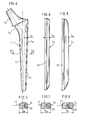
- the prosthesis body designated by the reference 1 in Figures 1 to 3, is a femoral prosthesis, of known general type, which has an elongated flat rod 11, a flange 14, and a Morse cone 10; the latter is intended to receive, in the usual manner, a femoral head.
- the outer edge 12 of the body 1 has a rectilinear shape; this edge is hollowed out with a longitudinal groove 13 of dovetail section.
- the width d of this groove increases very slightly when one moves from the proximal end (at the top of FIGS. 1 and 2) to its distal end (at the bottom of these figures); the width d2 of the groove at the proximal end is for example of the order of 4 mm while the width d, of the groove at its distal end is 4.5 mm.
- the groove 13 opens out at the two ends of the body 1.
- FIGs 4, 6 and 8 show three modular bars, which are intended to be selectively fixed in the prosthesis body 1 which has just been described.
- a strip 2a of small thickness Ea a strip 2b of average thickness Eb and a strip 2c of great thickness Ec.
- Each of these thicknesses is substantially constant from one end to the other of the strip considered. Note that these ends each have a curved outer edge, shaped to smoothly connect with the corresponding ends of the prosthesis body.
- Each bar 2a, 2b, 2c ... in accordance with the invention, has an identical internal edge 20, in the form of a rib, the dovetail section of which is complementary to that of the groove 13 in the body 1.
- FIG 4 there is shown the bar 2a after installation in the body 1. This establishment of the bar is done from bottom to top due to the decrease in this direction in the width d of the groove and the dovetail.
- the total width of the prosthesis device constituted by the prosthesis body 1 and the bar 2a, which has been designated D a, is for example equal to 15 mm at the level of the V-V plane.
- a thickness D b equal to 20 mm is obtained; similarly, if the bar 2c is used, a total width D equal to 25 mm is obtained.
- the device can be installed with or without cement; in the latter case, it may be desirable to provide during the manufacture of the prosthesis body, in the upper part thereof, asperities such as grooves, ribs, or a grid, intended to improve the retention of the prosthesis in the bone tissue.
- the principle of the invention could naturally be applied to prostheses other than hip prostheses, in particular to shoulder or knee prostheses.
Landscapes
- Health & Medical Sciences (AREA)
- Orthopedic Medicine & Surgery (AREA)
- Cardiology (AREA)
- Oral & Maxillofacial Surgery (AREA)
- Transplantation (AREA)
- Engineering & Computer Science (AREA)
- Biomedical Technology (AREA)
- Heart & Thoracic Surgery (AREA)
- Vascular Medicine (AREA)
- Life Sciences & Earth Sciences (AREA)
- Animal Behavior & Ethology (AREA)
- General Health & Medical Sciences (AREA)
- Public Health (AREA)
- Veterinary Medicine (AREA)
- Prostheses (AREA)
- Surgical Instruments (AREA)
Abstract
Description
- La présente invention concerne un dispositif de prothèse, notamment de prothèse articulaire, par exemple de prothèse de hanche (totale ou céphalique).
- La mise en place de ce type de prothèse pose un problème au chirurgien car les dimensions de la prothèse qui doit être utilisée, et notamment sa largeur, dépendent des dimensions de l'os qui doit la recevoir et, en particulier, de la largeur du canal médullaire de l'os.
- C'est pourquoi le bloc chirurgical doit avoir en permanence à sa disposition un stock important de prothèses de différentes largeurs échelonnées. L'immobilisation et la gestion de ce stock de pièces coûteuses, qui doit être maintenu en outre à l'état stérile, constitue une charge financière élevée pour les établissements hospitaliers ; de plus, le choix et l'utilisation des prothèses à partir d'un tel stock est peu pratique pour le chirurgien.
- Il a déjà été proposé, par le document EP-A-85 147, une prothèse d'articulation de la hanche - destinée à être implantée dans J'extrémité proximale du fémur -qui est constituée de deux parties indépendantes, un corps principal ou spatule et une pièce latérale cunéiforme ; cette dernière est adaptée pour coulisser dans un profil de guidage formé dans la face latérale étroite de la spatule.
- Ce dispositif connu permet apparemment de résoudre le problème qui vient d'être posé ; en effet, il est prévu dans le document EP-A-85 147 qu'on puisse disposer d'une série de pièces latérales de différentes épaisseurs, qui peuvent être combinées avec une même spatule afin de couvrir différentes largeurs de prothèse. Il est essentiellement destiné à permettre la mise en place de la prothèse à une hauteur bien déterminée dans l'extrémité du fémur. A cet effet, son implantation se fait en deux étapes :
- -mise en place de la spatule dans le canal médullaire, dans la position souhaitée ;
- -mise en place de la pièce latérale contre la spatule et enfoncement de cette pièce dans le fémur (tandis que la spatule est retenue dans la position souhaitée) jusqu'à ce que son bord externe cunéiforme vienne porter contre le tissu osseux et, par effet de coin, réalise le blocage de l'ensemble.
- Dans ce dispositif, le corps principal de la prothèse et la pièce latérale cunéiforme sont donc deux éléments initialement séparés, qui sont accolés l'un à l'autre seulement au cours de l'implantation de la prothèse. Ces éléments ne sont jamais véritablement solidaires l'un de l'autre si bien que leur manipulation par le chirurgien, avant et pendant l'implantation, est relativement délicate et source d'imprécisions. En outre, après l'implantation, les efforts se développant sur la prothèse -qui peuvent être très élevés et de directions variables - risquent de provoquer progressivement un jeu relatif entre les deux pièces et d'entraîner un descellement de l'ensemble.
- L'invention vise à remédier à ces inconvénients en proposant un dispositif de prothèse du genre énoncé dont la manipulation avant et pendant l'implantation soit aisée, et dont la retenue par l'os après implantation soit parfaite et durable.
- Ces résultats sont atteints, conformément à l'invention, par le fait que le dispositif de prothèse comprend un corps de prothèse de forme allongée et une série de barrettes modulaires d'épaisseurs différentes adaptées pour constituer avec le corps de prothèse un ensemble de largeur variable, et que chacune de ces barrettes présente un bord de section en queue-d'aronde apte à être emboîté dans une rainure de section complémentaire ménagée latéralement dans le corps de prothèse, cet emboîtement assurant la solidarisation mutuelle, en direction latérale, de ce corps avec la barrette.
- On comprendra aisément qu'il suffit ainsi que le bloc chirurgical ait à sa disposition un corps de prothèse unique, et un jeu complet de barrettes modulaires, pour pouvoir faire face à toutes les éventualités.
- De plus, l'emboîtement de la barrette sélectionnée dans le corps principal est effectué avant que commence l'implantation du dispositif, ce qui facilite considérablement le maniement de l'ensemble au cours de cette opération. Après mise en place, la dissociation des deux parties, par écartement latéral, est impossible.
- Chacune des barrettes présente avantageusement une épaisseur qui est sensiblement constante de l'une à l'autre de ses extrémités ; on obtient ainsi une bonne répartition des efforts d'appui avec le tissu osseux sur l'ensemble du dispositif, ce qui diminue encore le risque de descellement.
- Dans un mode de réalisation préférentiel de l'invention, le bord des barrettes en queue-d'aronde et la rainure de section complémentaire du corps de prothèse ont une largeur qui varie légèrement de l'une à l'autre de leurs extrémités.
- On réalise ainsi un auto-blocage de la queue- d'aronde dans la rainure associée au cours de sa mise en place (par effet de cônes auto-bloquants).
- Dans ce cas, il est avantageux de prévoir une largeur qui augmente de l'extrémité proximale vers l'extrémité distale, la barrette sélectionnée étant emboîtée de bas en haut dans le corps de prothèse. Ainsi, durant l'enfoncement de la prothèse dans le canal médullaire, les frottements du tissu osseux contre les parois de la barrette tendent à la faire remonter en améliorant encore son auto-blocage dans la rainure. Après mise en place, la barrette est complètement solidaire, à la fois dans les directions latérale et longitudinale, du corps de prothèse.
- L'invention sera mieux comprise, et ses particularités et avantages apparaîtront de la description et des dessins annexés, qui en représentent un mode de réalisation préférentiel.
- Les figures 1 et 2 sont respectivement des vues de face et de droite du corps de prothèse seul ;
- La figure 3 est une section horizontale selon le plan III-III de la figure 1 ;
- La figure 4 est une vue de face du corps de prothèse auquel on a fixé une barrette modulaire de faible épaisseur ;
- La figure 5 est une section horizontale suivant le plan V-V de la figure 4 ;
- Les figures 6 et 8 sont des vues de face de barrettes modulaires de moyenne et de grande épaisseurs respectivement ;
- Les figures 7 et 9 sont des coupes analogues à la figure 5, dans lesquelles le dispositif est équipé respectivement des barrettes des figures 6 et 8.
- Le corps de prothèse désigné par la référence 1 sur les figures 1 à 3, est une prothèse fémorale, de type général connu, qui présente une tige plate allongée 11, une collerette 14, et un cône morse 10 ; ce dernier est destiné à recevoir, de manière usuelle, une tête fémorale.
- Conformément à l'invention, le bord externe 12 du corps 1 a une forme rectiligne ; ce bord est creusé d'une rainure longitudinale 13 de section en queue-d'aronde. La largeur d de cette rainure augmente très légèrement lorsqu'on se déplace de l'extrémité proximale (en haut des figures 1 et 2) vers son extrémité distale (en bas de ces figures) ; la largeur d2 de If rainure à l'éxtrémité proximale est par exemple de l'ordre de 4 mm tandis que la largeur d, de la rainure à son extrémité distale est de 4,5 mm. La rainure 13 est débouchante aux deux extrémités du corps 1.
- Les figures 4, 6 et 8 représentent trois barrettes modulaires, qui sont destinées à être fixées sélectivement dans le corps de prothèse 1 qui vient d'être décrit.
- On a représenté une barrette 2a de faible épaisseur Ea, une barrette 2b d'épaisseur moyenne Eb et une barrette 2c de grande épaisseur Ec. Chacune de ces épaisseurs est sensiblement constante d'une extrémité à l'autre de la barrette considérée. A noter que ces extrémités présentent chacune un bord extérieur courbe, conformé pour se raccorder de manière douce avec les extrémités correspondantes du corps de prothèse.
- Chaque barrette 2a, 2b, 2c... , conformément à l'invention, présente un bord intérieur 20 identique, en forme de nervure, dont la section en queue- d'aronde est complémentaire de celle de la rainure 13 du corps 1.
- A la figure 4, on a représenté la barrette 2a après mise en place dans le corps 1. Cette mise en place de la barrette se fait de bas en haut en raison de la décroissance suivant cette direction de la largeur d de la rainure et de la queue-d'aronde.
- La largeur totale du dispositif de prothèse constitué par le corps de prothèse 1 et la barrette 2a, qui a été désignée D a, est par exemple égale à 15 mm au niveau du plan V-V.
- Si on utilise au lieu de la barrette 2a la barrette d'épaisseur moyenne 2b, on obtient une épaisseur Db égale à 20 mm ; de même, si on utilise la barrette 2c, on obtient une largeur totale D égale à 25 mm.
- Dans un but de simplification, on a représenté simplement trois barrettes modulaires différentes ; il va de soi que dans la pratique, il est souhaitable de prévoir un nombre de barrettes modulaires plus élevé, par exemple neuf barrettes dont les épaisseurs sont échelonnées de millimètre en millimètre.
- L'intérêt de l'invention se comprend directement de l'explication qui précède. En effet, en fonction des diamètres du fémur et du canal médullaire dans lequel il doit poser la prothèse (dimensions qu'il peut déduire des radiographies), le chirurgien sélectionne l'une des barrettes de la série qu'il a à sa disposition, met en place cette dernière dans le corps de prothèse, et pose l'ensemble du dispositif dans le canal médullaire à la manière d'une prothèse fémorale traditionnelle.
- Il va de soi que, selon les circonstances, le dispositif peut être posé avec ou sans ciment ; dans ce dernier cas, il peut être souhaitable de prévoir à la fabrication du corps de prothèse, dans la partie supérieure de celui-ci, des aspérités telles que des rainures, des nervures, ou un quadrillage, destinés à améliorer la retenue de la prothèse dans le tissu osseux.
- Il va de soi que l'invention n'est pas limitée au mode de réalisation préférentiel qui vient d'être décrit à simple titre d'exemple ; elle en embrasse au contraire toutes les variantes.
- C'est ainsi qu'il serait possible, bien entendu, de compléter la fixation de la barrette modulaire au corps de prothèse par des moyens additionnels, par exemple à l'aide d'une vis de blocage à tête noyée apte à immobiliser la barrette dans la rainure après son emboîtement de manière à empêcher son coulissement longitudinal.
- Par ailleurs, on ne sortirait naturellement pas du cadre de l'invention en inversant les éléments mâle et femelle du système d'assemblage à queue-d'aronde, c'est-à-dire en prévoyant la nervure sur le corps de prothèse et la rainure dans la barrette modulaire.
- Le principe de l'invention pourrait être naturellement appliqué à des prothèses autres que des prothèses de la hanche, notamment à des prothèses de l'épaule ou de genou.
Claims (5)
Priority Applications (1)
| Application Number | Priority Date | Filing Date | Title |
|---|---|---|---|
| AT86460004T ATE49346T1 (de) | 1985-04-05 | 1986-04-03 | Modulare prothesenvorrichtung. |
Applications Claiming Priority (2)
| Application Number | Priority Date | Filing Date | Title |
|---|---|---|---|
| FR8505348 | 1985-04-05 | ||
| FR8505348A FR2579887A1 (fr) | 1985-04-05 | 1985-04-05 |
Publications (3)
| Publication Number | Publication Date |
|---|---|
| EP0201442A2 true EP0201442A2 (fr) | 1986-12-17 |
| EP0201442A3 EP0201442A3 (en) | 1987-01-07 |
| EP0201442B1 EP0201442B1 (fr) | 1990-01-10 |
Family
ID=9318077
Family Applications (1)
| Application Number | Title | Priority Date | Filing Date |
|---|---|---|---|
| EP86460004A Expired - Lifetime EP0201442B1 (fr) | 1985-04-05 | 1986-04-03 | Dispositif de prothèse modulaire |
Country Status (7)
| Country | Link |
|---|---|
| US (1) | US4728333A (fr) |
| EP (1) | EP0201442B1 (fr) |
| JP (1) | JPS61288855A (fr) |
| AT (1) | ATE49346T1 (fr) |
| CA (1) | CA1260204A (fr) |
| DE (1) | DE3668115D1 (fr) |
| FR (1) | FR2579887A1 (fr) |
Cited By (12)
| Publication number | Priority date | Publication date | Assignee | Title |
|---|---|---|---|---|
| EP0217034A1 (fr) * | 1985-08-30 | 1987-04-08 | GebràDer Sulzer Aktiengesellschaft | Tige métallique droite pour prothèse de tête du fémur |
| EP0311208A1 (fr) * | 1987-10-05 | 1989-04-12 | Ordev B.V. | Prothèse ajustable |
| EP0359485A1 (fr) * | 1988-09-14 | 1990-03-21 | Pfizer Hospital Products Group, Inc. | Prothèse modulaire |
| FR2636837A1 (fr) * | 1988-09-23 | 1990-03-30 | Cremascoli Spa G | Prothese de hanche utilisable sans ciment |
| EP0366945A1 (fr) * | 1988-10-04 | 1990-05-09 | Intraplant AG | Prothèse fémorale avec un jeu d'ailettes |
| FR2639820A1 (fr) * | 1988-12-07 | 1990-06-08 | Implants Instr Ch Fab | Tiges femorales pour protheses totales de hanches |
| FR2641462A1 (fr) * | 1989-01-11 | 1990-07-13 | Cremascoli Spa G | Prothese de hanche a section variable comportant un profil constant |
| EP0405618A1 (fr) * | 1987-03-07 | 1991-01-02 | Hermann Dr. Künne | Endoprothése de la hanche |
| WO1994017757A1 (fr) * | 1993-02-09 | 1994-08-18 | Howmedica Inc. | Prothese de la hanche modulaire |
| FR2703583A1 (fr) * | 1993-04-07 | 1994-10-14 | Medinov Sa | Implant fémoral pour prothèse de hanche. |
| FR2720269A1 (fr) * | 1994-05-30 | 1995-12-01 | Medinov Sa | Dispositif de reprise chirurgicale d'une prothèse de hanche. |
| FR3020941A1 (fr) * | 2014-05-15 | 2015-11-20 | T O | Tige femorale avec collerette d'appui interne |
Families Citing this family (40)
| Publication number | Priority date | Publication date | Assignee | Title |
|---|---|---|---|---|
| FR2606997A1 (fr) * | 1986-08-25 | 1988-05-27 | Gilles Crespy | Prothese femorale mecanique auto-bloquee et procede de mise en oeuvre |
| FR2618323B1 (fr) * | 1987-07-21 | 1994-04-15 | Landos Applic Orthopediques Fses | Tige d'enclouage centro-medullaire |
| NL8901526A (nl) * | 1989-06-16 | 1991-01-16 | Ordev Bv | Zelf-instellende prothesebevestiging. |
| US5116335A (en) * | 1989-09-18 | 1992-05-26 | Hannon Gerard T | Intramedullary hybrid nail and instrumentation for installation and removal |
| US5100407A (en) * | 1990-09-04 | 1992-03-31 | Pfizer Hospital Products Group, Inc. | Modular trial hip replacement system |
| US20040010319A1 (en) * | 1998-04-14 | 2004-01-15 | Osteoimplant Technology Inc. | Intrinsic stability in a total hip stem |
| US7323013B2 (en) * | 1998-04-14 | 2008-01-29 | Encore Medical Asset Corporation | Differential porosity prosthetic hip system |
| US8114163B2 (en) * | 2000-04-10 | 2012-02-14 | Biomet Manufacturing Corp. | Method and apparatus for adjusting height and angle for a radial head |
| US8920509B2 (en) * | 2000-04-10 | 2014-12-30 | Biomet Manufacturing, Llc | Modular radial head prosthesis |
| US8535382B2 (en) | 2000-04-10 | 2013-09-17 | Biomet Manufacturing, Llc | Modular radial head prostheses |
| US7497874B1 (en) | 2001-02-23 | 2009-03-03 | Biomet Manufacturing Corp. | Knee joint prosthesis |
| US20020120340A1 (en) | 2001-02-23 | 2002-08-29 | Metzger Robert G. | Knee joint prosthesis |
| US6571444B2 (en) * | 2001-03-20 | 2003-06-03 | Vermon | Method of manufacturing an ultrasonic transducer |
| US7033399B2 (en) * | 2003-08-22 | 2006-04-25 | Ortho Innovations, Inc. | Welded hip prosthesis |
| US11213621B2 (en) | 2004-09-09 | 2022-01-04 | Reprieve Cardiovascular, Inc. | Fluid therapy method |
| FR2882922B1 (fr) * | 2005-03-08 | 2008-03-14 | Levon Doursounian | Implant humeral autobloquant pour l'osteosynthese ou le remplacement prothetique des fractures de l'extremite superieure de l'humerus |
| US20080167723A1 (en) * | 2006-03-20 | 2008-07-10 | Zimmer, Inc. | Prosthetic hip implants |
| US20080140211A1 (en) * | 2006-09-01 | 2008-06-12 | Doubler Robert L | Modular shoulder prosthesis with load bearing surface |
| US20080140210A1 (en) * | 2006-09-01 | 2008-06-12 | Doubler Robert L | Modular shoulder prosthesis |
| US8562616B2 (en) | 2007-10-10 | 2013-10-22 | Biomet Manufacturing, Llc | Knee joint prosthesis system and method for implantation |
| US8163028B2 (en) | 2007-01-10 | 2012-04-24 | Biomet Manufacturing Corp. | Knee joint prosthesis system and method for implantation |
| US8328873B2 (en) | 2007-01-10 | 2012-12-11 | Biomet Manufacturing Corp. | Knee joint prosthesis system and method for implantation |
| US8187280B2 (en) | 2007-10-10 | 2012-05-29 | Biomet Manufacturing Corp. | Knee joint prosthesis system and method for implantation |
| JP5448842B2 (ja) | 2007-01-10 | 2014-03-19 | バイオメト マニファクチャリング コーポレイション | 膝関節プロテーゼシステムおよび埋込み方法 |
| DE102007062151B3 (de) * | 2007-12-21 | 2008-12-24 | Heinz Kurz Gmbh Medizintechnik | Modulare Mittelohr-Totalprothese |
| US8529569B2 (en) * | 2010-03-05 | 2013-09-10 | Biomet Manufacturing, Llc | Method and apparatus for preparing a proximal femur |
| US8460393B2 (en) | 2010-03-05 | 2013-06-11 | Biomet Manufacturing Corp. | Modular lateral hip augments |
| US8221432B2 (en) | 2010-03-05 | 2012-07-17 | Biomet Manufacturing Corp. | Method and apparatus for implanting a modular femoral hip |
| US8419743B2 (en) * | 2010-03-05 | 2013-04-16 | Biomet Manufacturing Corp. | Assembly tool for modular implants and associated method |
| US8679130B2 (en) * | 2010-03-05 | 2014-03-25 | Biomet Manufacturing, Llc | Guide assembly for lateral implants and associated methods |
| US8333807B2 (en) | 2010-03-05 | 2012-12-18 | Biomet Manufacturing Corp. | Method and apparatus for trialing and implanting a modular femoral hip |
| TWI434668B (zh) | 2011-02-10 | 2014-04-21 | Metal Ind Res & Dev Ct | 具有模組化骨髓內釘之醫療器材 |
| CN102599970B (zh) * | 2012-03-31 | 2014-04-16 | 杨永竑 | 一种骨干内固定系统 |
| EP3794603B1 (fr) | 2018-05-18 | 2026-04-29 | Reprieve Cardiovascular, Inc. | Méthode et système pour traiter une insuffisance cardiaque décompensée aiguë |
| US12290380B1 (en) | 2018-08-20 | 2025-05-06 | Reprieve Cardiovascular, Inc. | Method and system to monitor urine output and manage fluid retention in a patient |
| CA3214843C (fr) | 2021-04-15 | 2025-05-27 | Reprieve Cardiovascular, Inc. | Systèmes de collecte d'urine et procédés et dispositifs associés |
| US12605702B2 (en) | 2021-04-26 | 2026-04-21 | Reprieve Cardiovascular, Inc. | Measuring and/or detecting analytes in urine, and associated systems, devices, and methods |
| US12564495B2 (en) * | 2023-07-19 | 2026-03-03 | Zimmer, Inc. | Stemmed modular implant system |
| US12257416B1 (en) | 2023-09-12 | 2025-03-25 | Reprieve Cardiovascular, Inc. | Fluid therapy based on sodium excretion, and associated systems, devices, and methods |
| WO2025175244A1 (fr) | 2024-02-16 | 2025-08-21 | Reprieve Cardiovascular, Inc. | Détection de sortie d'urine sans utilisation d'un cathéter à demeure, et systèmes, dispositifs et procédés associés |
Family Cites Families (12)
| Publication number | Priority date | Publication date | Assignee | Title |
|---|---|---|---|---|
| FR1158993A (fr) * | 1956-10-05 | 1958-06-20 | Maison Drapier | Broche à clavette tranchante pour enclouage centro-médullaire des os longs |
| US3918441A (en) * | 1974-09-17 | 1975-11-11 | Philip E Getscher | Intramedullary hip pin |
| US4285070A (en) * | 1978-06-05 | 1981-08-25 | Minnesota Mining And Manufacturing Company | Prosthetic device |
| US4340978A (en) * | 1979-07-02 | 1982-07-27 | Biomedical Engineering Corp. | New Jersey meniscal bearing knee replacement |
| US4309778A (en) * | 1979-07-02 | 1982-01-12 | Biomedical Engineering Corp. | New Jersey meniscal bearing knee replacement |
| AT363172B (de) * | 1979-09-07 | 1981-07-10 | Novex Foreign Trade Co Ltd | Markhoehlennagel |
| CH652911A5 (de) * | 1982-01-29 | 1985-12-13 | Sulzer Ag | Gerader, blattartiger schaft fuer eine gelenkendoprothese. |
| CH658185A5 (de) * | 1983-02-10 | 1986-10-31 | Sulzer Ag | Gerader, blattartiger schaft fuer eine gelenkendoprothese. |
| EP0135319A3 (fr) * | 1983-08-24 | 1985-07-24 | ARTHROPLASTY RESEARCH & DEVELOPMENT (PTY) LTD. | Prothèse d'articulation du genou |
| DE3340767A1 (de) * | 1983-11-08 | 1985-05-15 | Mecron Medizinische Produkte Gmbh, 1000 Berlin | Bausatz fuer eine resektionsprothese |
| EP0142759A3 (fr) * | 1983-11-22 | 1985-12-27 | Protek AG | Cuvette d'articulation de la hanche |
| EP0170982A1 (fr) * | 1984-07-26 | 1986-02-12 | Ivica Jerkovic | Endoprothèse d'articulation, particulièrement prothèse d'articulation de la hanche |
-
1985
- 1985-04-05 FR FR8505348A patent/FR2579887A1/fr not_active Withdrawn
-
1986
- 1986-04-03 DE DE8686460004T patent/DE3668115D1/de not_active Expired - Fee Related
- 1986-04-03 EP EP86460004A patent/EP0201442B1/fr not_active Expired - Lifetime
- 1986-04-03 AT AT86460004T patent/ATE49346T1/de not_active IP Right Cessation
- 1986-04-04 CA CA000505902A patent/CA1260204A/fr not_active Expired
- 1986-04-04 JP JP61078058A patent/JPS61288855A/ja active Pending
- 1986-04-07 US US06/848,505 patent/US4728333A/en not_active Expired - Fee Related
Cited By (16)
| Publication number | Priority date | Publication date | Assignee | Title |
|---|---|---|---|---|
| EP0217034A1 (fr) * | 1985-08-30 | 1987-04-08 | GebràDer Sulzer Aktiengesellschaft | Tige métallique droite pour prothèse de tête du fémur |
| EP0405618A1 (fr) * | 1987-03-07 | 1991-01-02 | Hermann Dr. Künne | Endoprothése de la hanche |
| EP0311208A1 (fr) * | 1987-10-05 | 1989-04-12 | Ordev B.V. | Prothèse ajustable |
| US4921499A (en) * | 1987-10-05 | 1990-05-01 | Ordev B.V. | Adjustable prosthesis |
| EP0359485A1 (fr) * | 1988-09-14 | 1990-03-21 | Pfizer Hospital Products Group, Inc. | Prothèse modulaire |
| US5108437A (en) * | 1988-09-14 | 1992-04-28 | Pfizer Hospital Products Group, Inc. | Modular prosthesis |
| FR2636837A1 (fr) * | 1988-09-23 | 1990-03-30 | Cremascoli Spa G | Prothese de hanche utilisable sans ciment |
| CH675962A5 (fr) * | 1988-10-04 | 1990-11-30 | Hermann Ag W | |
| EP0366945A1 (fr) * | 1988-10-04 | 1990-05-09 | Intraplant AG | Prothèse fémorale avec un jeu d'ailettes |
| FR2639820A1 (fr) * | 1988-12-07 | 1990-06-08 | Implants Instr Ch Fab | Tiges femorales pour protheses totales de hanches |
| FR2641462A1 (fr) * | 1989-01-11 | 1990-07-13 | Cremascoli Spa G | Prothese de hanche a section variable comportant un profil constant |
| WO1994017757A1 (fr) * | 1993-02-09 | 1994-08-18 | Howmedica Inc. | Prothese de la hanche modulaire |
| US5549706A (en) * | 1993-02-09 | 1996-08-27 | Howmedica Inc. | Modular hip prosthesis |
| FR2703583A1 (fr) * | 1993-04-07 | 1994-10-14 | Medinov Sa | Implant fémoral pour prothèse de hanche. |
| FR2720269A1 (fr) * | 1994-05-30 | 1995-12-01 | Medinov Sa | Dispositif de reprise chirurgicale d'une prothèse de hanche. |
| FR3020941A1 (fr) * | 2014-05-15 | 2015-11-20 | T O | Tige femorale avec collerette d'appui interne |
Also Published As
| Publication number | Publication date |
|---|---|
| US4728333A (en) | 1988-03-01 |
| EP0201442A3 (en) | 1987-01-07 |
| ATE49346T1 (de) | 1990-01-15 |
| DE3668115D1 (de) | 1990-02-15 |
| EP0201442B1 (fr) | 1990-01-10 |
| CA1260204A (fr) | 1989-09-26 |
| FR2579887A1 (fr) | 1986-10-10 |
| JPS61288855A (ja) | 1986-12-19 |
Similar Documents
| Publication | Publication Date | Title |
|---|---|---|
| EP0201442B1 (fr) | Dispositif de prothèse modulaire | |
| EP0179695B1 (fr) | Prothèse vertébrale, en particulier pour vertèbres cervicales | |
| EP1221912B1 (fr) | Prothese de disque intervertebral a faces dentees | |
| EP1194087B1 (fr) | Implant intersomatique anatomique | |
| EP1039855B1 (fr) | Prothese discale partielle | |
| EP3687455A1 (fr) | Prothèse de cheville comportant un implant talien, un implant tibial et un insert, et kit incluant au moins une telle prothèse | |
| EP1815824A1 (fr) | Implant tibial a tige offset | |
| FR2874814A1 (fr) | Cage intervertebrale | |
| EP0834295A1 (fr) | Prothèse d'arthrodèse intersomatique vertébrale | |
| FR2794362A1 (fr) | Implant intervertebral et ensemble de pose d'un tel implant | |
| EP0871419A1 (fr) | Implant intervertebral du type cage intersomatique | |
| EP0913134A2 (fr) | Prothèse de genou | |
| FR2926719A1 (fr) | Ensemble compose d'une embase tibiale et d'un insert tibial et prothese comprenant un tel ensemble | |
| EP2676637B1 (fr) | Ensemble d'implants fémoraux pour une prothèse du genou | |
| EP1862150A1 (fr) | Prothèse totale d'articulation du genou | |
| FR2923155A1 (fr) | Implant intervertebral destine a permettre d'immobiliser une vertebre par rapport a une autre | |
| FR2668702A1 (fr) | Tige femorale perfectionnee pour prothese de hanche. | |
| FR2780636A1 (fr) | Prothese de genou modulable | |
| FR2812540A1 (fr) | Prothese bicompartimentale du genou | |
| EP3593764B1 (fr) | Implant de glène de prothèse d'épaule et procédé pour la fabrication de cet implant | |
| EP3395272A1 (fr) | Implant d'arthrodèse et kit chirurgical comprenant un tel implant | |
| FR2676914A1 (fr) | Prothese femorale anatomique. | |
| FR2738739A1 (fr) | Prothese de genou unicondylienne du type dit "a glissement" | |
| EP0112423A1 (fr) | Prothèse articulaire, et notamment prothèse fémorale, à tige intramédullaire auto-blocante en forme de coin | |
| EP1703853B1 (fr) | Implant dentaire |
Legal Events
| Date | Code | Title | Description |
|---|---|---|---|
| PUAI | Public reference made under article 153(3) epc to a published international application that has entered the european phase |
Free format text: ORIGINAL CODE: 0009012 |
|
| PUAL | Search report despatched |
Free format text: ORIGINAL CODE: 0009013 |
|
| AK | Designated contracting states |
Kind code of ref document: A2 Designated state(s): AT BE CH DE GB IT LI LU NL SE |
|
| PUAB | Information related to the publication of an a document modified or deleted |
Free format text: ORIGINAL CODE: 0009199EPPU |
|
| AK | Designated contracting states |
Kind code of ref document: A3 Designated state(s): AT BE CH DE GB IT LI LU NL SE |
|
| RA1 | Application published (corrected) |
Date of ref document: 19861217 Kind code of ref document: A2 |
|
| 17P | Request for examination filed |
Effective date: 19870704 |
|
| 17Q | First examination report despatched |
Effective date: 19890502 |
|
| GRAA | (expected) grant |
Free format text: ORIGINAL CODE: 0009210 |
|
| AK | Designated contracting states |
Kind code of ref document: B1 Designated state(s): AT BE CH DE GB IT LI LU NL SE |
|
| PG25 | Lapsed in a contracting state [announced via postgrant information from national office to epo] |
Ref country code: IT Free format text: LAPSE BECAUSE OF FAILURE TO SUBMIT A TRANSLATION OF THE DESCRIPTION OR TO PAY THE FEE WITHIN THE PRE;WARNING: LAPSES OF ITALIAN PATENTS WITH EFFECTIVE DATE BEFORE 2007 MAY HAVE OCCURRED AT ANY TIME BEFORE 2007. THE CORRECT EFFECTIVE DATE MAY BE DIFFERENT FROM THE ONE RECORDED.SCRIBED TIME-LIMIT Effective date: 19900110 Ref country code: AT Effective date: 19900110 Ref country code: SE Effective date: 19900110 Ref country code: NL Effective date: 19900110 Ref country code: GB Effective date: 19900110 |
|
| REF | Corresponds to: |
Ref document number: 49346 Country of ref document: AT Date of ref document: 19900115 Kind code of ref document: T |
|
| REF | Corresponds to: |
Ref document number: 3668115 Country of ref document: DE Date of ref document: 19900215 |
|
| PG25 | Lapsed in a contracting state [announced via postgrant information from national office to epo] |
Ref country code: LU Free format text: LAPSE BECAUSE OF NON-PAYMENT OF DUE FEES Effective date: 19900430 Ref country code: CH Effective date: 19900430 Ref country code: LI Effective date: 19900430 Ref country code: BE Effective date: 19900430 |
|
| NLV1 | Nl: lapsed or annulled due to failure to fulfill the requirements of art. 29p and 29m of the patents act | ||
| GBV | Gb: ep patent (uk) treated as always having been void in accordance with gb section 77(7)/1977 [no translation filed] | ||
| BERE | Be: lapsed |
Owner name: FRANCE IMPLANT Effective date: 19900430 |
|
| PLBE | No opposition filed within time limit |
Free format text: ORIGINAL CODE: 0009261 |
|
| STAA | Information on the status of an ep patent application or granted ep patent |
Free format text: STATUS: NO OPPOSITION FILED WITHIN TIME LIMIT |
|
| 26N | No opposition filed | ||
| REG | Reference to a national code |
Ref country code: CH Ref legal event code: PL |
|
| PG25 | Lapsed in a contracting state [announced via postgrant information from national office to epo] |
Ref country code: DE Effective date: 19910101 |