EP0201493B1 - Vehicule a essieux multiples avec entrainement independant des roues - Google Patents
Vehicule a essieux multiples avec entrainement independant des roues Download PDFInfo
- Publication number
- EP0201493B1 EP0201493B1 EP85900459A EP85900459A EP0201493B1 EP 0201493 B1 EP0201493 B1 EP 0201493B1 EP 85900459 A EP85900459 A EP 85900459A EP 85900459 A EP85900459 A EP 85900459A EP 0201493 B1 EP0201493 B1 EP 0201493B1
- Authority
- EP
- European Patent Office
- Prior art keywords
- drive
- joint
- wheel
- casing
- vehicle according
- Prior art date
- Legal status (The legal status is an assumption and is not a legal conclusion. Google has not performed a legal analysis and makes no representation as to the accuracy of the status listed.)
- Expired
Links
- 230000005540 biological transmission Effects 0.000 claims description 31
- 230000008878 coupling Effects 0.000 claims description 8
- 238000010168 coupling process Methods 0.000 claims description 8
- 238000005859 coupling reaction Methods 0.000 claims description 8
- 238000007789 sealing Methods 0.000 claims description 5
- 230000001360 synchronised effect Effects 0.000 claims 1
- 238000010276 construction Methods 0.000 abstract 1
- 238000009434 installation Methods 0.000 description 5
- 230000010354 integration Effects 0.000 description 3
- 230000002349 favourable effect Effects 0.000 description 2
- 238000004519 manufacturing process Methods 0.000 description 2
- 230000004308 accommodation Effects 0.000 description 1
- 238000005452 bending Methods 0.000 description 1
- 230000009286 beneficial effect Effects 0.000 description 1
- 238000011161 development Methods 0.000 description 1
- 230000018109 developmental process Effects 0.000 description 1
- 238000010586 diagram Methods 0.000 description 1
- 238000012423 maintenance Methods 0.000 description 1
- 230000014759 maintenance of location Effects 0.000 description 1
- 239000000463 material Substances 0.000 description 1
- 238000004904 shortening Methods 0.000 description 1
- 239000004575 stone Substances 0.000 description 1
- 239000000725 suspension Substances 0.000 description 1
Images

Classifications
-
- B—PERFORMING OPERATIONS; TRANSPORTING
- B60—VEHICLES IN GENERAL
- B60K—ARRANGEMENT OR MOUNTING OF PROPULSION UNITS OR OF TRANSMISSIONS IN VEHICLES; ARRANGEMENT OR MOUNTING OF PLURAL DIVERSE PRIME-MOVERS IN VEHICLES; AUXILIARY DRIVES FOR VEHICLES; INSTRUMENTATION OR DASHBOARDS FOR VEHICLES; ARRANGEMENTS IN CONNECTION WITH COOLING, AIR INTAKE, GAS EXHAUST OR FUEL SUPPLY OF PROPULSION UNITS IN VEHICLES
- B60K17/00—Arrangement or mounting of transmissions in vehicles
- B60K17/04—Arrangement or mounting of transmissions in vehicles characterised by arrangement, location or kind of gearing
- B60K17/043—Transmission unit disposed in on near the vehicle wheel, or between the differential gear unit and the wheel
- B60K17/046—Transmission unit disposed in on near the vehicle wheel, or between the differential gear unit and the wheel with planetary gearing having orbital motion
-
- B—PERFORMING OPERATIONS; TRANSPORTING
- B60—VEHICLES IN GENERAL
- B60K—ARRANGEMENT OR MOUNTING OF PROPULSION UNITS OR OF TRANSMISSIONS IN VEHICLES; ARRANGEMENT OR MOUNTING OF PLURAL DIVERSE PRIME-MOVERS IN VEHICLES; AUXILIARY DRIVES FOR VEHICLES; INSTRUMENTATION OR DASHBOARDS FOR VEHICLES; ARRANGEMENTS IN CONNECTION WITH COOLING, AIR INTAKE, GAS EXHAUST OR FUEL SUPPLY OF PROPULSION UNITS IN VEHICLES
- B60K17/00—Arrangement or mounting of transmissions in vehicles
- B60K17/28—Arrangement or mounting of transmissions in vehicles characterised by arrangement, location, or type of power take-off
-
- B—PERFORMING OPERATIONS; TRANSPORTING
- B60—VEHICLES IN GENERAL
- B60K—ARRANGEMENT OR MOUNTING OF PROPULSION UNITS OR OF TRANSMISSIONS IN VEHICLES; ARRANGEMENT OR MOUNTING OF PLURAL DIVERSE PRIME-MOVERS IN VEHICLES; AUXILIARY DRIVES FOR VEHICLES; INSTRUMENTATION OR DASHBOARDS FOR VEHICLES; ARRANGEMENTS IN CONNECTION WITH COOLING, AIR INTAKE, GAS EXHAUST OR FUEL SUPPLY OF PROPULSION UNITS IN VEHICLES
- B60K17/00—Arrangement or mounting of transmissions in vehicles
- B60K17/34—Arrangement or mounting of transmissions in vehicles for driving both front and rear wheels, e.g. four wheel drive vehicles
Definitions
- the invention relates to a multi-axle vehicle with single wheel drives according to the preamble of claim 1 and is particularly directed to improvements for single wheel sprung multi-purpose vehicles that should be able to endure both high speeds and rough terrain.
- FR-A-831 375 shows vehicles of this type, in which the wheels can be driven by off-center drive trains arranged near the wheels via bevel gear transfer gears Transfer case can also be achieved with articulated axles, without either restricting the spring travel of the individual drive shafts due to the proximity of the wheels or having to operate their joints with unfavorable deflection angles.
- a wheel drive in which the joint and transmission are combined into a compact structural unit by means of a pot-like bearing of the joint, is known from DE-C-734 379.
- the center of the joint is housed in a space-saving manner within a hollow shaft carrying a bevel gear of the transfer case, but at the same time, due to the fact that this shaft is supported on both sides, the possibility is blocked that the transmission can be crossed by a straight, further drive train to further axes driven in parallel. Since this is a prerequisite for realizing multi-axle vehicles with more than two driven axles, the known wheel drive cannot be used for vehicles with more than two driven axles or in cases in which clutches or power take-offs are located in the transfer case.
- DE-A-28 35 865 shows a multi-axle vehicle of this type, in which the individual transfer cases for the drive shafts leading to the wheels are crossed by further drive trains.
- the joint is not in a pot-like bearing within the transmission, but with a considerable distance outside the housing and on the wheel side from the bearing of the ring gear shaft. Therefore, there is no shortening of the distances between the wheel and transmission and no better utilization of the drive shaft working angle for a higher ground clearance etc.
- the object of the invention is therefore to provide a multi-axle vehicle with independent wheel drives in near-wheel drive trains in which, despite given short distances to the wheel or wheel transmission, connecting shafts with joints can be connected in such a way that a large ground clearance and sufficiently large deflection paths can nevertheless be made possible that all drive elements can withstand normal high demands and can be set up a wide low-floor in the vehicle.
- the large bearings offer not only a high load rating, but also the advantage of good accessibility of the joint despite the compact accommodation within the hub of the axle drive wheel, which in the example is designed as a bevel gear, but can also be conceivable as a spur gear in a front or planetary gear.
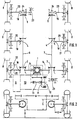
- a multi-axle vehicle is shown with three single-wheel-driven axles, all of which are to be individually drivable via a central 1 and further gearboxes 2, 3, 4, 5 near the wheel.
- two drive trains 6, 7 have been selected which are placed as close as possible to the wheels 8 in order to achieve a large ground clearance with a sufficient width in the central region of the vehicle, or to be able to pull the loading space down deeply.
- the transversely arranged engine 9 and manual transmission 10 is followed by a primary bevel gear 11 with a connected parking brake 12, which depending on the height conditions can also be driven via a propeller shaft 13 and in turn rigidly drives into an axle center drive 1 (main differential), from which on each side, possibly as propeller shafts developable differential shafts 15 to a transfer case 2, 3 near the wheel.
- axle center drive 1 main differential
- these are provided with drive shaft end 16 and coaxial 17 and one (at 2) or two right-angled drives 18 (at 3).
- the coaxial drives 17 go here via a joint 19, which is included in the transfer case 2 or 3 and in which the respective connecting shaft 20 is mounted as close as possible to the middle of the transmission.
- the middle of the Transfer case 2 or 3 is usually located at a fully loaded vehicle approximately at the center of the assigned wheel 8 and as close to it as the connecting shaft 20 or its joints 19 in transfer case 2 or 3 and 21 in wheel 8 or allow 22 in the gearbox.
- This proximity is further increased according to the invention, in particular by the length gain due to the integration of the joints 19 in the respective transmission compared to previously known cardan shaft designs, without the connecting shafts 20 being too short or their deflection angles at the joints 19, 21 being too large. Where necessary, deflection angles of more than 50 ° can be provided.
- the axle shaft speeds in front of the joints are still kept relatively high and only the following wheel gear 22 is designed with a high reduction ratio, which then leads to larger moments and corresponding shaft diameters.
- the drive trains 6 and 7, respectively, of the transfer case 2 and 3 closest to the axle center transmission 1 in the example, can also be kept small or light.
- the first transfer case 3 near the wheel in the example on the right has a second right-angled branch, for. B. for a PTO shaft connection 23. If only a simple single-wheel drive is to be branched off from the respective drive train 6 or 7 parallel to the direction of travel, one version of the transfer case with a continuous drive shaft and right-angled outlet 4 is sufficient.
- axle shaft 20 also to connect the drive train ends driving into the relevant transfer case 4 with joints in the same way, if a flexible vehicle frame structure is present.
- joints are not shown here.
- the transfer case with a continuous drive shaft 6 or 7 and a connecting shaft 20 extending at right angles preferably have the same main dimensions as those with a drive shaft 14 (2 or 3) driving coaxially to the axle shaft 20, and also those 5, with a built-in shutdown device 24, as is preferably provided the steering axles of the multi-axle vehicle are provided.
- the advantages of the invention of course also apply to other axis arrangements.
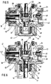
- Fig. 2 shows a section through the gear arrangement with the ground clearance obtained in width A by the wheel proximity of the drive trains, which allows the vehicle floor to be lowered by the dimension C by the ground clearance B above the terrain.
- the cargo space with the width D remaining above the transfer case can in future be used as a seat for benches etc.
- Decisive for the width A of the low-floor is the installation length E of the connecting shafts to the wheels due to the specified dimensions of the transfer case.
- Both the large diameter of the support collar 26 and its widening 30 increasing on the wheel side allow the axle shaft 20 to have a sufficiently large deflection angle 31 while at the same time gaining an effectively usable axis length by more than the length 32 of the support collar 26 compared to the conventional joint arrangement outside of transfer case housings.
- the wheel-side sealing takes place here via a funnel-shaped sealing bellows 33, which is clamped between the axle shafts 20 and the support collar 26 so that a single crease 34 comes to lie just in front of the joint 19 and its otherwise smooth lateral surfaces 35, 36 the deflection angle 31 of the axle shaft 20 practically do not interfere.
- the joint 19 is designed as a so-called internally centered constant velocity joint, its space requirement is particularly favorable.
- the housing collar 28 carrying the support collar 26 is very large, preferably larger than the joint 19 itself, and therefore the support collar 26 also has a large diameter, there is also a particularly high load-bearing capacity in addition to a lot of space for the pivoting connecting shaft 20 Drive wheel bearings for high performance and long service life even with unsteady speed behavior.
- the entire assembled joint 19 can be inserted with the connecting shaft 20 together with the support collar 26 and the housing bearing 28th be inserted and fixed in a flange-like manner in the housing 25.
- the example of FIG. 3 shows the drive wheel 27 designed as a bevel gear driven by an approximately equally large drive wheel 37 on the drive shaft 6 and 7, which have drive shaft bearings 40 with shaft seals at both through openings 38, 39 of the housing 25.
- the shaft sections (6 and 7) held within the housing 25 can be connected in the example outside the housing 25 via shaft connections 41 to extension sections (not shown) of the drive trains.
- extension sections (not shown) of the drive trains.
- a bearing socket 44 for such a second input or output gear 43 and its associated shaft (for example 14) is provided in the housing base 42, which could, if desired, be equipped here with a joint 19 for the opposite connecting shaft 20, without requiring additional space.
- FIG. 5 shows the housing 25, which is basically the same, but without a continuous drive shaft 6 (FIG. 7), only with a right-angled output to the connecting shaft 20, but with a disconnection device 45 of the same from the drive train.
- the ability to be switched off 45 is here a coupling piece 47 which carries a sliding sleeve 46 and which rotates with the support collar 26 of the joint 19.
- the sliding sleeve 46 By means of the sliding sleeve 46, it can be operatively connected to a switching toothing 48 of the drive wheel 43 arranged on the side of the housing 25 opposite the joint 19.
- a drive wheel 27 directly connected to the joint 19 is not required in this variant.
- the sliding sleeve 46 can be actuated here via a pressure medium actuator 49 mounted in the housing 25 and also inserted into the housing 25 with a displaceable shift lever 50 and is accessible via a further housing cover 51 which is arranged at right angles to the connecting shaft 20.
- the omission of the continuous drive shaft 6 (7) allows the drive and driven wheels 37, 43 in this arrangement that the joint 19 is drawn almost to the center of the driven wheel 37 into the center of the gear housing 25 because the length gain 32 for the axle shaft 20 can be increased approximately by the strength of the shaft 6 or 7 and the support collar 26 only has to have a shorter housing bearing 28 due to the omission of the direct drive wheel 27.
- the switch-off device 45 can also be arranged in a different way, e.g. B. with multi-plate clutch, limited slip differential, overrunning clutch and the like, but the advantage achieved by the arrangement according to the invention remains much longer than the clearance 4 between wheel 8 or wheel hub gear 22 and the transfer case 1 ...
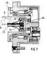
- Fig. 7 shows the transfer case as a wheel head gear with a planetary gear, in which the joint 19 is also built in accordance with the features of the invention up to the transmission side of the axle bearings in the transmission housing 25, so that thereby the effective length of the connecting shaft 20 (distance of the joints to the Connecting shaft ends) is extended by about half the length of the wheel head without affecting the deflection angle.
- the support collar 26, to which the outer rings of the joint 19 are fastened, is here also a sun gear shaft which is mounted in a ring gear carrier.
- the wheel bearing is fixed on the hub carrier with the same nuts that also hold the ring gear.
- the length of the joint in the hub corresponds approximately to that of the large, closely spaced axle bearing.
- the support ring 26 or the outer ring of the joint 19 can also be directly toothed as a sun gear, around which the planetary or gear head gear is then built.
Landscapes
- Engineering & Computer Science (AREA)
- Chemical & Material Sciences (AREA)
- Combustion & Propulsion (AREA)
- Transportation (AREA)
- Mechanical Engineering (AREA)
- Arrangement And Driving Of Transmission Devices (AREA)
- Arrangement And Mounting Of Devices That Control Transmission Of Motive Force (AREA)
- Arrangement Of Transmissions (AREA)
- Automatic Cycles, And Cycles In General (AREA)
- Electric Propulsion And Braking For Vehicles (AREA)
Claims (14)
caractérisé en ce que :
Applications Claiming Priority (2)
| Application Number | Priority Date | Filing Date | Title |
|---|---|---|---|
| EP8400008 | 1984-01-13 | ||
| WOPCT/EP84/00008 | 1984-01-13 |
Publications (2)
| Publication Number | Publication Date |
|---|---|
| EP0201493A1 EP0201493A1 (fr) | 1986-11-20 |
| EP0201493B1 true EP0201493B1 (fr) | 1987-11-04 |
Family
ID=8164926
Family Applications (1)
| Application Number | Title | Priority Date | Filing Date |
|---|---|---|---|
| EP85900459A Expired EP0201493B1 (fr) | 1984-01-13 | 1984-12-19 | Vehicule a essieux multiples avec entrainement independant des roues |
Country Status (7)
| Country | Link |
|---|---|
| US (1) | US4718509A (fr) |
| EP (1) | EP0201493B1 (fr) |
| AT (1) | ATE30545T1 (fr) |
| BR (1) | BR8407370A (fr) |
| DE (2) | DE3467125D1 (fr) |
| WO (1) | WO1985003042A1 (fr) |
| ZA (1) | ZA849305B (fr) |
Families Citing this family (13)
| Publication number | Priority date | Publication date | Assignee | Title |
|---|---|---|---|---|
| DE3629297A1 (de) * | 1985-10-04 | 1987-04-09 | Zahnradfabrik Friedrichshafen | Einzelradantrieb mittels einer verbindungswelle |
| DE3542059C1 (de) * | 1985-11-28 | 1987-06-04 | Opel Adam Ag | Kraftfahrzeug mit Hauptantriebsachse und zuschaltbarer Antriebsachse |
| FR2611613B1 (fr) * | 1987-02-24 | 1991-01-18 | Renault | Dispositif de transmission a quatre roues motrices |
| AT394983B (de) * | 1988-03-04 | 1992-08-10 | Johann Nussmueller | Vierachsiges fahrzeug mit allradantrieb und allradlenkung |
| DE69101677D1 (de) * | 1990-07-27 | 1994-05-19 | Joy Mfg Co Africa | Antriebsstrang. |
| US5285866A (en) * | 1990-07-27 | 1994-02-15 | Joy Manufacturing Company (Africa) Limited (Pty) | Drive train |
| DE4424442A1 (de) * | 1994-07-12 | 1996-01-18 | Kloeckner Humboldt Deutz Ag | Antriebsvorrichtung für landwirtschaftliche Erntemaschinen |
| US5636699A (en) * | 1995-07-26 | 1997-06-10 | Pitman, I; Samuel D. | Mobile hauling vehicle |
| DE10227418A1 (de) * | 2002-06-20 | 2004-01-08 | Zf Friedrichshafen Ag | Antriebsstrang für ein Kraftfahrzeug |
| DE102007053266A1 (de) * | 2007-11-08 | 2009-05-14 | Agco Gmbh | Nutzfahrzeug mit mindestens drei antreibbaren Fahrzeugachsen |
| US10363813B2 (en) * | 2014-11-24 | 2019-07-30 | Ge Global Sourcing Llc | Integrated motor and axle apparatus and method |
| CN108422855A (zh) * | 2018-05-04 | 2018-08-21 | 吉林大学 | 一种可原地转向的抢险救援车传动系统 |
| CN113619683B (zh) * | 2021-09-13 | 2024-12-24 | 姚连涛 | 一种车辆底盘以及车辆 |
Family Cites Families (15)
| Publication number | Priority date | Publication date | Assignee | Title |
|---|---|---|---|---|
| GB191112038A (en) * | 1910-05-26 | 1912-02-15 | Lentz Getriebe G M B H | Improvements in or connected with the Live Axles of Motor Vehicles. |
| GB104384A (en) * | 1916-03-01 | 1917-03-01 | Gordon Watney | Improvements in Power Transmission Gear for Self-propelled Vehicles. |
| FR810821A (fr) * | 1936-04-16 | 1937-03-31 | Mécanisme de transmission et de direction pour automobiles | |
| FR831375A (fr) * | 1936-12-28 | 1938-09-01 | Klein | Système de commande des roues d'un véhicule |
| GB523654A (en) * | 1938-10-17 | 1940-07-19 | Birmingham Small Arms Co Ltd | Improvements in or relating to motor vehicles |
| DE734379C (de) * | 1940-10-11 | 1943-04-14 | Carl F W Borgward | Kraftfahrzeug mit Vierradantrieb |
| GB656586A (en) * | 1948-09-24 | 1951-08-29 | Nat Res Dev | Improvements in and relating to transmission mechanism for vehicles |
| US3058558A (en) * | 1959-09-01 | 1962-10-16 | Allis Chalmers Mfg Co | Coupling mechanism |
| GB1060660A (en) * | 1963-11-26 | 1967-03-08 | Rolls Royce | Improvements relating to motor vehicles |
| DE1902942A1 (de) * | 1969-01-22 | 1970-08-27 | Porsche Kg | Lagerung von Fahrzeugraedern,insbesondere von angetriebenen Kraftfahrzeugraedern |
| US3768821A (en) * | 1972-04-04 | 1973-10-30 | Ford Motor Co | Split torque drivetrain for multiple wheel vehicle |
| US3930550A (en) * | 1974-08-15 | 1976-01-06 | The United States Of America As Represented By The Secretary Of The Army | Vehicle drive and suspension |
| US4273460A (en) * | 1978-08-11 | 1981-06-16 | Nissan Motor Company, Limited | Axle construction for four wheel drive vehicles or the like |
| DE2835865C2 (de) * | 1978-08-16 | 1986-11-27 | Hermann Dr.-Ing. 3302 Cremlingen Klaue | Kraftwagen |
| FR2530547A1 (fr) * | 1982-07-21 | 1984-01-27 | Renault Vehicules Ind | Moyeu de roue comportant un engrenage reducteur pour essieu directeur |
-
1984
- 1984-11-29 ZA ZA849305A patent/ZA849305B/xx unknown
- 1984-12-19 US US06/777,788 patent/US4718509A/en not_active Expired - Fee Related
- 1984-12-19 EP EP85900459A patent/EP0201493B1/fr not_active Expired
- 1984-12-19 BR BR8407370A patent/BR8407370A/pt not_active IP Right Cessation
- 1984-12-19 WO PCT/EP1984/000412 patent/WO1985003042A1/fr not_active Ceased
- 1984-12-19 DE DE19843467125 patent/DE3467125D1/de not_active Expired
- 1984-12-19 DE DE19843446271 patent/DE3446271A1/de not_active Withdrawn
- 1984-12-19 AT AT85900459T patent/ATE30545T1/de not_active IP Right Cessation
Also Published As
| Publication number | Publication date |
|---|---|
| ZA849305B (en) | 1985-07-31 |
| ATE30545T1 (de) | 1987-11-15 |
| EP0201493A1 (fr) | 1986-11-20 |
| DE3446271A1 (de) | 1985-07-18 |
| BR8407370A (pt) | 1987-03-10 |
| US4718509A (en) | 1988-01-12 |
| DE3467125D1 (fr) | 1987-12-10 |
| WO1985003042A1 (fr) | 1985-07-18 |
Similar Documents
| Publication | Publication Date | Title |
|---|---|---|
| DE102012100865B4 (de) | Antriebsanordnung mit elektrischer Maschine und Kraftfahrzeug mit einer solchen Antriebsanordnung | |
| DE102008037886B4 (de) | Antriebsanordnung für ein mehrachsgetriebenes Kraftfahrzeug | |
| EP1551658B1 (fr) | Vehicule pourvu d'entrainements electriques individuels des roues | |
| DE4108647C2 (fr) | ||
| DE3027806C2 (de) | Triebachse für Omnibusse | |
| EP0201493B1 (fr) | Vehicule a essieux multiples avec entrainement independant des roues | |
| DE102005004290B4 (de) | Getriebemodul zur variablen Drehmomentverteilung | |
| DE10253259A1 (de) | Universell gestaltbares Kraftfahrzeuggetriebe | |
| DE69825917T2 (de) | Antriebseinheit für ein elektrisch angetriebenes Niederflurfahrzeug | |
| EP3888981B1 (fr) | Entraînement d'essieu | |
| CH668042A5 (de) | Antriebsanordnung fuer ein einsatzfahrzeug, insbesondere feuerwehrfahrzeug. | |
| WO2009135456A1 (fr) | Agencement de transmission peu encombrant | |
| WO2015014449A1 (fr) | Chaîne cinématique d'un véhicule automobile | |
| DE60319794T2 (de) | Getriebe für ein Rad-Arbeitsfahrzeug | |
| DE69518507T2 (de) | Fahrantriebsvorrichtung für arbeitsfahrzeug | |
| DE102008022939A1 (de) | Achsantriebsanordnung eines Fahrzeugs mit Verteilergetriebe | |
| DE3602930A1 (de) | Allradantrieb fuer ein kraftfahrzeug | |
| DE102021200523A1 (de) | Antriebsstrang für ein Kraftfahrzeug sowie Kraftfahrzeug mit wenigstens einem solchen Antriebsstrang | |
| DE102006038358B4 (de) | Achsantriebseinheit für einen Antriebsstrang | |
| DE2239955A1 (de) | Zahnraederwechselgetriebe, insbesondere fuer land- und/oder bauwirtschaftlich nutzbare motorfahrzeuge | |
| WO2006114331A1 (fr) | Unite de transmission differentielle a commande active de la repartition du couple | |
| DE4323539C1 (de) | Radlagereinheit eines Kraftfahrzeugs | |
| DE4409224A1 (de) | Allradantrieb | |
| EP2179881B1 (fr) | Véhicule automobile doté d'un entraînement toute roue | |
| WO2020030434A1 (fr) | Essieu de véhicule comprenant un dispositif d'entraînement électrique et dispositif d'entraînement électrique |
Legal Events
| Date | Code | Title | Description |
|---|---|---|---|
| PUAI | Public reference made under article 153(3) epc to a published international application that has entered the european phase |
Free format text: ORIGINAL CODE: 0009012 |
|
| 17P | Request for examination filed |
Effective date: 19860612 |
|
| AK | Designated contracting states |
Kind code of ref document: A1 Designated state(s): AT CH DE FR GB LI |
|
| 17Q | First examination report despatched |
Effective date: 19870413 |
|
| GRAA | (expected) grant |
Free format text: ORIGINAL CODE: 0009210 |
|
| AK | Designated contracting states |
Kind code of ref document: B1 Designated state(s): AT CH DE FR GB LI |
|
| REF | Corresponds to: |
Ref document number: 30545 Country of ref document: AT Date of ref document: 19871115 Kind code of ref document: T |
|
| REF | Corresponds to: |
Ref document number: 3467125 Country of ref document: DE Date of ref document: 19871210 |
|
| ET | Fr: translation filed | ||
| GBT | Gb: translation of ep patent filed (gb section 77(6)(a)/1977) | ||
| PLBE | No opposition filed within time limit |
Free format text: ORIGINAL CODE: 0009261 |
|
| STAA | Information on the status of an ep patent application or granted ep patent |
Free format text: STATUS: NO OPPOSITION FILED WITHIN TIME LIMIT |
|
| 26N | No opposition filed | ||
| PGFP | Annual fee paid to national office [announced via postgrant information from national office to epo] |
Ref country code: AT Payment date: 19911205 Year of fee payment: 8 |
|
| PGFP | Annual fee paid to national office [announced via postgrant information from national office to epo] |
Ref country code: CH Payment date: 19920212 Year of fee payment: 8 |
|
| PG25 | Lapsed in a contracting state [announced via postgrant information from national office to epo] |
Ref country code: AT Effective date: 19921219 |
|
| PG25 | Lapsed in a contracting state [announced via postgrant information from national office to epo] |
Ref country code: LI Effective date: 19921231 Ref country code: CH Effective date: 19921231 |
|
| REG | Reference to a national code |
Ref country code: CH Ref legal event code: PL |
|
| PGFP | Annual fee paid to national office [announced via postgrant information from national office to epo] |
Ref country code: GB Payment date: 19991122 Year of fee payment: 16 |
|
| PGFP | Annual fee paid to national office [announced via postgrant information from national office to epo] |
Ref country code: FR Payment date: 19991216 Year of fee payment: 16 |
|
| PGFP | Annual fee paid to national office [announced via postgrant information from national office to epo] |
Ref country code: DE Payment date: 19991229 Year of fee payment: 16 |
|
| PG25 | Lapsed in a contracting state [announced via postgrant information from national office to epo] |
Ref country code: GB Free format text: LAPSE BECAUSE OF NON-PAYMENT OF DUE FEES Effective date: 20001219 |
|
| GBPC | Gb: european patent ceased through non-payment of renewal fee |
Effective date: 20001219 |
|
| PG25 | Lapsed in a contracting state [announced via postgrant information from national office to epo] |
Ref country code: FR Free format text: LAPSE BECAUSE OF NON-PAYMENT OF DUE FEES Effective date: 20010831 |
|
| REG | Reference to a national code |
Ref country code: FR Ref legal event code: ST |
|
| PG25 | Lapsed in a contracting state [announced via postgrant information from national office to epo] |
Ref country code: DE Free format text: LAPSE BECAUSE OF NON-PAYMENT OF DUE FEES Effective date: 20011002 |