EP0201620B1 - Serrure-commutateur - Google Patents
Serrure-commutateur Download PDFInfo
- Publication number
- EP0201620B1 EP0201620B1 EP85106099A EP85106099A EP0201620B1 EP 0201620 B1 EP0201620 B1 EP 0201620B1 EP 85106099 A EP85106099 A EP 85106099A EP 85106099 A EP85106099 A EP 85106099A EP 0201620 B1 EP0201620 B1 EP 0201620B1
- Authority
- EP
- European Patent Office
- Prior art keywords
- lock
- cylinder
- contacts
- key
- switch
- Prior art date
- Legal status (The legal status is an assumption and is not a legal conclusion. Google has not performed a legal analysis and makes no representation as to the accuracy of the status listed.)
- Expired
Links
- 230000037431 insertion Effects 0.000 claims abstract 2
- 238000003780 insertion Methods 0.000 claims abstract 2
- 238000005728 strengthening Methods 0.000 claims abstract 2
- 210000002105 tongue Anatomy 0.000 claims description 6
- 230000003068 static effect Effects 0.000 description 5
- 230000015572 biosynthetic process Effects 0.000 description 2
- 238000005755 formation reaction Methods 0.000 description 2
- 230000007257 malfunction Effects 0.000 description 2
- 239000002184 metal Substances 0.000 description 2
- 230000006835 compression Effects 0.000 description 1
- 238000007906 compression Methods 0.000 description 1
- 238000006073 displacement reaction Methods 0.000 description 1
- 230000005669 field effect Effects 0.000 description 1
- 239000007924 injection Substances 0.000 description 1
- 238000002347 injection Methods 0.000 description 1
- 230000002093 peripheral effect Effects 0.000 description 1
- 238000004080 punching Methods 0.000 description 1
- 230000003014 reinforcing effect Effects 0.000 description 1
Images

Classifications
-
- H—ELECTRICITY
- H05—ELECTRIC TECHNIQUES NOT OTHERWISE PROVIDED FOR
- H05F—STATIC ELECTRICITY; NATURALLY-OCCURRING ELECTRICITY
- H05F3/00—Carrying-off electrostatic charges
- H05F3/02—Carrying-off electrostatic charges by means of earthing connections
-
- H—ELECTRICITY
- H01—ELECTRIC ELEMENTS
- H01H—ELECTRIC SWITCHES; RELAYS; SELECTORS; EMERGENCY PROTECTIVE DEVICES
- H01H27/00—Switches operated by a removable member, e.g. key, plug or plate; Switches operated by setting members according to a single predetermined combination out of several possible settings
- H01H27/06—Key inserted and then turned to effect operation of the switch
Definitions
- the invention relates to a switch lock according to the preamble of claim 1, as is used for example in telephone dialing keyboards to set different possible uses.
- a switch lock which can be rotated with the aid of a key inserted through a slot in the pushbutton into different switching positions, a first contact set being set, which is arranged at the rear end of the switch lock. By pressing the button, a second set of contacts on the side of the key switch can also be operated.
- a lock is constructed as follows: Within a lock holder, a lock body is arranged, in which a lock cylinder can be rotated.
- locking elements can be moved transversely to the cylinder axis, which are aligned with the cylinder surface when the key is inserted and otherwise protrude beyond the cylinder surface and engage in locking recesses in the lock body, so that it cannot be rotated.
- the locking recesses are lined with metallic, U-shaped reinforcing profile parts.
- a locking disk connected to the lock cylinder in cooperation with locking springs, fixes the individual switching positions of the first contact set located at the rear end of the lock cylinder.
- the push button protrudes through an attachment screwed to the lock holder, and - when the button is pressed, the lateral second contact sets, which can be switched as earth contacts, are actuated via intermediate elements.
- the object of the invention is to provide measures by means of which such voltage injections via the switching lock are avoided.
- this object is achieved in a switch lock of the type mentioned by the characterizing features of claim 1.
- a switch plate is provided for the key switch, which is used to discharge any static charges to the ground when the key is inserted, without reaching the contacts connected to the voltage-sensitive circuit.
- the deflector is arranged between the lock top and lock holder and runs on the one hand at a short distance or in contact with at least one of the profile parts and on the other hand at a short distance at least with a part of the key switch carrying earth potential.
- the key When the key is inserted, its metal parts touch the likewise metallic locking elements of the lock cylinder, which in turn touch the metallic profile parts in the locking recesses.
- the deflector plate has a cutout corresponding to the cross section of the lock body and at least one tongue to be protruded inward through a corresponding recess in the lock body onto the rear of the profile part.
- the tongue can touch the profile part backwards, but a small distance is also sufficient, which is jumped over by the high voltage introduced as a spark gap.
- the side contact sets connected as earth contacts can serve as the parts carrying earth potential and, in order to form a second spark gap, the deflecting plate can expediently be provided with a shape at the location of the earth contacts, from the location of which is closest to the earth contact spring a spark can jump onto the contact spring.
- Such a deflector can be produced easily and inexpensively by punching if the shape according to a particular embodiment of the invention has, for example, the shape of a cutout of such depth that the earth contact spring is opposite the cutout in the idle state and the edge part of the deflecting plate bridging the cutout.
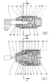
- a lock holder 1 within which a lock body 2 is arranged, which in turn encloses a lock cylinder 3.
- a lock attachment 4 is seated on the lock holder 1 (both parts can be held together by a screw connection), and a pushbutton 5 is mounted in the lock attachment 4 and is pressed outwards by a compression spring 6.
- a key 8 can be pushed into the lock and thus into the lock cylinder 3.
- the key 8 has tumblers 9 for locking elements which have the shape of locking plates 10 in the plate lock shown here and are mounted in transverse slots of the lock cylinder 3.
- tumblers 9 of the key 8 are in the correct position relative to the plate 10, the latter are aligned with the cylinder surface of the lock cylinder 3, so that it can be freely rotated in the lock. If the tumblers do not correspond in position with the plates 10, these protrude upwards or downwards beyond the cylinder surface of the lock cylinder into groove-shaped locking recesses 11 of the lock body, which are reinforced with U-shaped metal profile parts 11a, and block the lock cylinder against twisting .
- a locking disc 12 which rotates together with the lock cylinder 3 and is formed with locking surfaces 13, against which locking springs 14 are applied in order to fix the various switching positions of the lock cylinder.
- On the locking disc 12 contacts 15 of a first set of contacts are attached, which cooperate with counter-contacts 16, which in turn sit in a plate 1 a attached to the lock holder 1.
- the key 8 is formed with a nose 8a, which lies when the key is inserted into the lock against the end face 5a of the push button 5.
- This forms a first stop which marks the closed position of the key switch, in which the key 8 is inserted so far into the lock cylinder 3 that the strikers 10 are brought into such a position by the tumblers 9 of the key 8 against the pressure of their springs align them with the cylinder surface of the lock cylinder: Then the lock cylinder 3 can be rotated and the first set of contacts with the contacts 15 and 16 can be brought into a desired contact position.
- the angle of rotation of the lock cylinder is limited by a locking pin 17a in conjunction with a circumferential recess 17 running in the circumferential direction in the lock cylinder 3, which is continued here in two - but possibly also more - axial recesses 17b, which allow the lock cylinder 3 to be axially displaced in those switching positions which the push button 5 should be able to push in for actuating a second or third contact set 21, 22 (in the other switching positions, the wall of the circumferential recess 17 prevents axial displacement of the lock cylinder 3 and thus pushing in the push button 5 connected to the lock cylinder).
- Fig. 2 shows that the second and third contact set is formed with internal contacts 21 and external contacts 22 which are attached to the side of the lock holder 1.
- the inner contacts 21 can be pressed outwardly against the outer contacts 22 via intermediate members designed as sliders 23, which are located in axial grooves of the lock body 2, when the pushing button 5 presses their peripheral rim 29 against an attachment 23b of the relevant slider 23, which is then displaced in its axial groove against the force of a spring 24.
- the deflector is shaped so that it produces a low-resistance connection between the key 8 and the contacts 21, 22 used as earth contacts in relation to the stroke distance between the key tip and the first contact set 15, 16.
- This low-resistance overvoltage discharge path runs from the key 8 via the locking plate 10 and the profile parts 11a to the tongues 26 of the deflector plate 25, which protrude through corresponding recesses 24 in the lock body 2 onto the rear sides of the profile parts 11a.
- the tongues 26 do not necessarily have to touch the profile parts 11a on the rear side thereof, for assembly reasons there may be a slight distance which is easily overcome by the high voltage.
- 22 adjacent to the earth contacts of the deflector plate 25 formations 27 are provided in the form of cutouts to guarantee free movement of the contact springs.
- the rollover distance between the tips of the contact springs and the remaining webs 28 is sufficiently small compared to the stroke distance between the key tip and the rear contact sets, so that any overvoltages are kept away from them.
- the key touches the locking plate 10 when it is inserted into the key switch before it is inserted as far as it will go, so that the surge arrester is established before the key tip has reached its shortest distance to the rear contact sets, so that surge voltages are derived beforehand.
- the example of an embodiment shown in the drawings is characterized by extremely small dimensions, such as those prescribed for use with a telephone keypad.
- the length from the end face of the pushbutton 5 to the rear end of the lock holder is only 28.5 mm, and the overall width including the second contact sets is only 18.5 mm, and the height is even smaller.
- the deflector plate 25 can also take other forms.
- the formations 27 not to be designed as cutouts if sufficient freedom of movement of the earth contacts is also ensured in another way.
- parts of the deflector plate can be brought closer to the contact springs, for example by appropriate deformations of the deflector plate near the contact springs, for example by punched projections or tongues bent towards the contact springs, etc. It is only important that the deflector plate has a ratio to the mentioned impact distance to the rear contact sets low-impedance overvoltage path between the beard of the key 8 and parts of the switching lock that lead to ground potential, these grounding parts in the exemplary embodiment just described usually being earth contacts of the switch, but also due to other parts of the switch that are at ground potential can be formed, e.g. B. if it is a key switch without pushbutton or earth contacts.
Landscapes
- Push-Button Switches (AREA)
- Tumbler Switches (AREA)
- Lock And Its Accessories (AREA)
Claims (5)
Priority Applications (3)
| Application Number | Priority Date | Filing Date | Title |
|---|---|---|---|
| DE8585106099T DE3561779D1 (en) | 1985-05-17 | 1985-05-17 | Switch lock |
| EP85106099A EP0201620B1 (fr) | 1985-05-17 | 1985-05-17 | Serrure-commutateur |
| AT85106099T ATE32803T1 (de) | 1985-05-17 | 1985-05-17 | Schaltschloss. |
Applications Claiming Priority (1)
| Application Number | Priority Date | Filing Date | Title |
|---|---|---|---|
| EP85106099A EP0201620B1 (fr) | 1985-05-17 | 1985-05-17 | Serrure-commutateur |
Publications (2)
| Publication Number | Publication Date |
|---|---|
| EP0201620A1 EP0201620A1 (fr) | 1986-11-20 |
| EP0201620B1 true EP0201620B1 (fr) | 1988-03-02 |
Family
ID=8193507
Family Applications (1)
| Application Number | Title | Priority Date | Filing Date |
|---|---|---|---|
| EP85106099A Expired EP0201620B1 (fr) | 1985-05-17 | 1985-05-17 | Serrure-commutateur |
Country Status (3)
| Country | Link |
|---|---|
| EP (1) | EP0201620B1 (fr) |
| AT (1) | ATE32803T1 (fr) |
| DE (1) | DE3561779D1 (fr) |
Families Citing this family (2)
| Publication number | Priority date | Publication date | Assignee | Title |
|---|---|---|---|---|
| CN102313860B (zh) * | 2011-07-28 | 2013-09-04 | 国家电网公司 | 笼形滚动式火花间隙测零装置 |
| CN113990704B (zh) * | 2021-11-26 | 2024-09-17 | 山东盖伊尔智能电气有限公司 | 一种高压开关柜接地开关挂锁装置 |
Family Cites Families (2)
| Publication number | Priority date | Publication date | Assignee | Title |
|---|---|---|---|---|
| US4009357A (en) * | 1975-10-01 | 1977-02-22 | Oak Industries Inc. | Anti-static keylock switch |
| DE3224789A1 (de) * | 1982-07-02 | 1984-01-05 | Hauck Gmbh, 8016 Feldkirchen | Drucktasten-schaltschloss mit exklusiv-schaltposition |
-
1985
- 1985-05-17 AT AT85106099T patent/ATE32803T1/de not_active IP Right Cessation
- 1985-05-17 DE DE8585106099T patent/DE3561779D1/de not_active Expired
- 1985-05-17 EP EP85106099A patent/EP0201620B1/fr not_active Expired
Also Published As
| Publication number | Publication date |
|---|---|
| EP0201620A1 (fr) | 1986-11-20 |
| DE3561779D1 (en) | 1988-04-07 |
| ATE32803T1 (de) | 1988-03-15 |
Similar Documents
| Publication | Publication Date | Title |
|---|---|---|
| EP0295437B1 (fr) | Dispositif de bouton-poussoirs | |
| DE4009279C2 (fr) | ||
| DE69601885T2 (de) | Verriegelbarer Tastschalter | |
| EP0727797B1 (fr) | Interrupteur de sécurité | |
| DE2717136A1 (de) | Schalter | |
| DE2025504B2 (de) | Schiebetastenschalteranordnung | |
| EP0201620B1 (fr) | Serrure-commutateur | |
| DE102006031584B4 (de) | Miniaturisierter elektrischer Schalter | |
| EP0708464B1 (fr) | Commutateur électrique | |
| DE2559861B1 (de) | Verriegelbarer Drucktastenschalter | |
| EP1040499B1 (fr) | Dispositif de couplage | |
| AT403607B (de) | Schliesseinrichtung mit einem zylinderschloss und einem wendeflachschlüssel | |
| EP0301469A2 (fr) | Générateur d'impulsions | |
| DE3018810C2 (fr) | ||
| EP0157186B1 (fr) | Commutateur à curseur verrouillable | |
| DE2904646C2 (de) | Drucktastenschalter | |
| DE1074124B (de) | Kon taktfedersatz insbesondere fur Einrich tungen der Nachrichten vermittlungstechnik | |
| EP0076450B1 (fr) | Interrupteur électrique à bouton-poussoir | |
| DE69208609T2 (de) | Diebstahlsicherungsschalter für Kraftfahrzeug | |
| DE3821612C1 (en) | Electrical switch | |
| DE3324253A1 (de) | Tastenschalter | |
| DE4418707A1 (de) | Schnappschalter mit gerader Bewegung des Schaltstücks sowie Schaltersystem hierzu | |
| DE3210033C2 (fr) | ||
| DE8317080U1 (de) | Lenkschloß mit Schalter, insbesondere für Kraftfahrzeuge | |
| EP0319606A1 (fr) | Commutateur avec coupe-circuit |
Legal Events
| Date | Code | Title | Description |
|---|---|---|---|
| PUAI | Public reference made under article 153(3) epc to a published international application that has entered the european phase |
Free format text: ORIGINAL CODE: 0009012 |
|
| 17P | Request for examination filed |
Effective date: 19860310 |
|
| AK | Designated contracting states |
Kind code of ref document: A1 Designated state(s): AT CH DE FR IT LI |
|
| 17Q | First examination report despatched |
Effective date: 19870511 |
|
| ITF | It: translation for a ep patent filed | ||
| GRAA | (expected) grant |
Free format text: ORIGINAL CODE: 0009210 |
|
| AK | Designated contracting states |
Kind code of ref document: B1 Designated state(s): AT CH DE FR IT LI |
|
| REF | Corresponds to: |
Ref document number: 32803 Country of ref document: AT Date of ref document: 19880315 Kind code of ref document: T |
|
| REF | Corresponds to: |
Ref document number: 3561779 Country of ref document: DE Date of ref document: 19880407 |
|
| ET | Fr: translation filed | ||
| PLBE | No opposition filed within time limit |
Free format text: ORIGINAL CODE: 0009261 |
|
| STAA | Information on the status of an ep patent application or granted ep patent |
Free format text: STATUS: NO OPPOSITION FILED WITHIN TIME LIMIT |
|
| 26N | No opposition filed | ||
| PGFP | Annual fee paid to national office [announced via postgrant information from national office to epo] |
Ref country code: CH Payment date: 19890503 Year of fee payment: 5 |
|
| PGFP | Annual fee paid to national office [announced via postgrant information from national office to epo] |
Ref country code: FR Payment date: 19890718 Year of fee payment: 5 |
|
| PG25 | Lapsed in a contracting state [announced via postgrant information from national office to epo] |
Ref country code: LI Effective date: 19900531 Ref country code: CH Effective date: 19900531 |
|
| PGFP | Annual fee paid to national office [announced via postgrant information from national office to epo] |
Ref country code: DE Payment date: 19901130 Year of fee payment: 6 |
|
| PG25 | Lapsed in a contracting state [announced via postgrant information from national office to epo] |
Ref country code: FR Effective date: 19910131 |
|
| REG | Reference to a national code |
Ref country code: CH Ref legal event code: PL |
|
| REG | Reference to a national code |
Ref country code: FR Ref legal event code: ST |
|
| PGFP | Annual fee paid to national office [announced via postgrant information from national office to epo] |
Ref country code: AT Payment date: 19910513 Year of fee payment: 7 |
|
| PG25 | Lapsed in a contracting state [announced via postgrant information from national office to epo] |
Ref country code: DE Effective date: 19920303 |
|
| PG25 | Lapsed in a contracting state [announced via postgrant information from national office to epo] |
Ref country code: AT Effective date: 19920517 |