EP0201624A2 - Circuit ballast pour lampe fluorescente - Google Patents
Circuit ballast pour lampe fluorescente Download PDFInfo
- Publication number
- EP0201624A2 EP0201624A2 EP85111393A EP85111393A EP0201624A2 EP 0201624 A2 EP0201624 A2 EP 0201624A2 EP 85111393 A EP85111393 A EP 85111393A EP 85111393 A EP85111393 A EP 85111393A EP 0201624 A2 EP0201624 A2 EP 0201624A2
- Authority
- EP
- European Patent Office
- Prior art keywords
- fluorescent lamp
- current
- signal
- ballast according
- lamp
- Prior art date
- Legal status (The legal status is an assumption and is not a legal conclusion. Google has not performed a legal analysis and makes no representation as to the accuracy of the status listed.)
- Withdrawn
Links
Images

Classifications
-
- H—ELECTRICITY
- H05—ELECTRIC TECHNIQUES NOT OTHERWISE PROVIDED FOR
- H05B—ELECTRIC HEATING; ELECTRIC LIGHT SOURCES NOT OTHERWISE PROVIDED FOR; CIRCUIT ARRANGEMENTS FOR ELECTRIC LIGHT SOURCES, IN GENERAL
- H05B41/00—Circuit arrangements or apparatus for igniting or operating discharge lamps
- H05B41/14—Circuit arrangements
- H05B41/36—Controlling
- H05B41/38—Controlling the intensity of light
- H05B41/39—Controlling the intensity of light continuously
- H05B41/392—Controlling the intensity of light continuously using semiconductor devices, e.g. thyristor
-
- H—ELECTRICITY
- H05—ELECTRIC TECHNIQUES NOT OTHERWISE PROVIDED FOR
- H05B—ELECTRIC HEATING; ELECTRIC LIGHT SOURCES NOT OTHERWISE PROVIDED FOR; CIRCUIT ARRANGEMENTS FOR ELECTRIC LIGHT SOURCES, IN GENERAL
- H05B41/00—Circuit arrangements or apparatus for igniting or operating discharge lamps
- H05B41/14—Circuit arrangements
- H05B41/26—Circuit arrangements in which the lamp is fed by power derived from DC by means of a converter, e.g. by high-voltage DC
- H05B41/28—Circuit arrangements in which the lamp is fed by power derived from DC by means of a converter, e.g. by high-voltage DC using static converters
- H05B41/295—Circuit arrangements in which the lamp is fed by power derived from DC by means of a converter, e.g. by high-voltage DC using static converters with semiconductor devices and specially adapted for lamps with preheating electrodes, e.g. for fluorescent lamps
- H05B41/298—Arrangements for protecting lamps or circuits against abnormal operating conditions
- H05B41/2988—Arrangements for protecting lamps or circuits against abnormal operating conditions for protecting the lamp against abnormal operating conditions
Definitions
- the invention relates to a fluorescent lamp ballast with a power supply circuit that feeds two parallel circuit branches, each of which leads via an electrode of the fluorescent lamp and contains two electronic switches in series, a control unit for controlling the electronic switch, an inductor for generating the ignition voltage for the fluorescent lamp and a current sensor.
- the usual electronic fluorescent lamp ballasts contain a series resonant circuit that is triggered by an inverter and generates an oscillation whose frequency is above the hearing range of the human ear.
- the fluorescent lamp is connected in parallel to the capacitor of the series resonant circuit.
- Such ballasts have the Disadvantage that the fluorescent lamp is operated at a relatively high frequency and causes high-frequency electromagnetic interference. At the high frequency, parasitic line capacitances become effective, so that in order to achieve reproducible properties, a defined line routing from the device to the fluorescent lamps is required. Difficulties arise particularly when the fluorescent lamp is removed from the socket or when its resistance has become too great due to aging.
- ballasts mentioned require additional safety circuits to ensure that operation only takes place when a fluorescent lamp used is functioning properly.
- the known ballasts are each designed only for a narrow power range of the fluorescent lamp and for a very limited range of supply voltages. Different ballasts must be used for different lamp powers, lamp voltages and supply voltages.
- the fluorescent lamp is supplied with a high-frequency voltage, the lamp current depending on various parameters, for example the lamp resistance.
- the lamp resistance depending on various parameters, for example the lamp resistance.
- the invention has for its object to provide a fluorescent lamp ballast of the type mentioned, which can be used equally for lamps with different lamp powers and different lamp voltages.
- the current sensor and the inductor are connected in series with the two circuit branches and that the current sensor controls a switching element which is also connected in series in such a way that this switching element opens the circuit when the current has a specific value exceeds the first threshold and closes the circuit when the current falls below a certain second threshold that is lower than the first threshold.
- the current drawn by the circuit branches current ie the L ampenstrom constantly remains in the range between the first and the second threshold value and is thus kept almost constant.
- a defined current is therefore supplied to the lamp, which is independent of the level of the externally applied voltage and also independent of the lamp resistance.
- the lamp current is kept almost lossless because the switching element is either in the on state or in the off state in each phase.
- the switching element is in the on state, the current through the inductance in the lamp circuit increases slowly until the first threshold value is reached. The switching element is then blocked so that the inductance discharges and the current slowly drops to the second threshold value.
- the inductance which ensures a slow increase and slow decrease in the lamp current within the bandwidth specified by the two threshold values, can simultaneously be used to generate the high voltage required to ignite the fluorescent lamp.
- the threshold values can be changed individually or together depending on at least one control signal.
- the ballast can, for example, perform a dimmer function if the threshold values are changed by a control signal which can be influenced manually. If the thresholds are high, the lamp current is high and the lamp is bright; If the threshold values are lowered, the lamp current becomes smaller and the lamp shines less brightly.
- To regulate threshold values automatically for example depending on the illuminance prevailing in the room in which the fluorescent lamp is located or depending on the lamp temperature.
- the ballast can be supplied with different supply voltages, for example with a mains voltage of 110 V and a frequency of 60 Hz or with a mains voltage of 220 V and 50 Hz. Since the lamp current is kept constant regardless of the supply voltage , the ballast works with different supply voltages without switching.
- the two threshold voltages can preferably be changed together, so that the bandwidth of the current fluctuations does not change when the current amplitude changes.
- the electronic switches are controlled in such a way that the fluorescent lamp is reversed with a frequency below 100 Hz.
- the polarity reversal frequency should be below 1 Hz and preferably below 1 mHz.
- the fluorescent lamp is operated to a certain extent with direct current, with a polarity reversal taking place at relatively large time intervals.
- the polarity reversal is necessary to prevent cataphoresis in the fluorescent lamp. Cataphoresis occurs when the lamp is operated with the same polarity for a long time. It is a mercury displacement for a K-Thode out, which can be dismantled by reversing the polarity of the lamp.
- the polarity reversal can take place at relatively large intervals of, for example, one hour. This would correspond to a pole reversal frequency of approx. 0.3 mHz. While the usual ballasts with one above the According to the invention, the polarity reversal frequency of the lamp is made low. The lamp current is kept constant in every half period, the switchover is only from time to time to avoid cataphoresis.
- An integration device is preferably provided which forms the time integral over this current during each period of the current flowing through the fluorescent lamp and initiates the next period when this integral has become zero.
- the polarity reversal of the fluorescent lamp does not necessarily take place with a constant half-period.
- the lamp current in the second half-period may differ from that in the first half-period, e.g. if the lamp current has been changed by dimming.
- the time integral is formed over the current in each of the half-periods, and when the integrals of the positive and negative half-periods are equal to one another, the period is ended.
- the integral formation takes place, particularly in the case of long half-periods, preferably by converting the current values into digital form and adding them up cumulatively.
- ballast Since the current is regulated in the ballast according to the invention, there are numerous possibilities for influencing this current in order to achieve different operating states of the fluorescent lamp.
- a particular advantage is that the ballast can be used without structural changes for fluorescent lamps with different powers by the size of the lamp current according to the lamp power is set. This setting can be made either on a manually adjustable signal transmitter or depending on the parameters of the fluorescent lamp used in the ballast. In the latter case, the lamp current required by the fluorescent lamp in question is set automatically.
- the ballast according to the invention also enables the use of a dimmer circuit with which the lamp current is changed as a function of an external control signal.
- This control signal can be generated either by manually adjusting the dimmer circuit or by an external sensor.
- a particular problem with fluorescent lamp ballasts is starting the fluorescent lamp. Before starting, the electrodes of the fluorescent lamp are preheated for a certain time with direct currents. Thereafter, several ignition attempts are made in succession in the known ballasts by interrupting both circuit branches which lead over the electrodes of the fluorescent lamp, ie by briefly blocking one of the electronic switches for the passage of current. The inductance then briefly supplies a high ignition voltage. According to a preferred embodiment of the invention, numerous short firing pulses are with short time A b stands supplied to one pair of diagonally arranged electronic switch to open and close periodically. The repetition frequency of the ignition pulses is so high that the charge carriers in the interior of the fluorescent lamp cannot essentially recombine between two ignition pulses. In this way, the ignition takes place after several ignition pulses.
- the ignitability of the Fluorescent lamp builds up like a staircase curve.
- a particular advantage is that the inductance required for ignition can be kept relatively small. This inductance is reduced by a factor of n compared to the usual ignition with individual pulses, where n represents the number of briefly successive ignition pulses.
- the smaller inductance not only reduces the required coil dimensions and iron weight, but also the stored energy.
- the electronic switches are not destroyed even in the event of voltage breakdowns, since the low energy stored in the coil is not sufficient for this.
- the electronic switch used for ignition is only held in the blocking state for as long as a reversible voltage breakdown occurs at this switch, but the switch is not destroyed. In the event of a voltage breakdown, the blocked electronic switch behaves like a zener diode.
- the second breakdown leading to destruction which is referred to as thermal breakdown, is avoided by the current limitation.
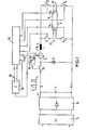
- the ballast shown in FIG. 1 has a rectifier circuit 10, which is fed with an alternating voltage via a low-pass filter 11 for eliminating interference voltages from or into the supply network.
- the rectifier circuit 10 generates a DC voltage on the capacitor C, which does not have to be regulated, and the level of which may depend on the applied mains voltage.
- the switching element T S which is a switching transistor, is connected to the positive pole of the supply voltage.
- the switching element T and the electronic switches to be described below are shown in the drawing as mechanical switches.
- the switching element T S is connected in series with the current sensor I and the inductance L.
- the parallel connection of the two circuit branches 12 and 13 is connected to this series connection.
- the other end of this parallel connection is connected to the negative pole of the rectifier 10.
- the circuit branch 12 contains the electronic switches T 1 and T 3 , between which the one electrode 14 1 the fluorescent lamp 14 is switched.
- the other circuit branch 13 contains the series connection of the transistors T 2 and T 4 , between which the second electrode 14 2 of the fluorescent lamp 14 is connected.
- the switches T 1 to T 4 are controlled by the logic control unit 15, which can be a microprocessor, for example.
- the comparator 16 generates two threshold values from the reference voltage, one of which corresponds to a maximum lamp current i L max and the other to a minimum lamp current i L min.
- the comparator 16 blocks the switching element T S , ie the series circuit is interrupted.
- the inductance L now tries to maintain the current that has previously flowed, so that the coil current i L slowly drops.
- this current reaches the lower limit value i Z min, the comparator 16 switches the switching element T S back into the conductive state, as a result of which the lamp current i L in the series circuit rises again.
- the electrodes 14 1 and 14 2 are first heated.
- all four switches T 1 to T 4 are controlled in the conductive state.
- two diagonally opposite switches, for example switches T 1 and T 4 are blocked.
- the current i L can be changed by appropriately controlling the comparator 16.
- the inductance L generates the voltage rise required for the ignition of the lamp 14.
- the lamp is now operated for a longer period of time, for example over an hour, using switches T 2 and T 3 , electrode 14 2 having a positive potential and electrode 14 1 having a negative potential.
- FIG. 3 shows the lamp current i L over time t, but the time scale is much larger than that of FIG. 2.
- the output signal of the current sensor I is integrated by the integrator 18. From Fig. 3 it can be seen that the integral f iL dt increases linearly with time. This integral is fed from the integrator 18 to the control unit 15. When the integral has reached a predetermined maximum value, the control unit 15 causes the switches T 1 and T 4 to be kept conductive and the switches T 2 and T 3 are subsequently blocked. The current then flows through T 1 , the lamps 14 and T 4 , so that the lamp 14 is reversed.
- the integrator 18 is reversed so that it is now integrated downwards.
- the upward and downward integration is controlled by the logic control unit 15 via the lines 19.
- the second half period 2HP is ended and the switches T 2 and T 3 become conductive again, and subsequently the switches T 1 and T 4 are blocked. It is thus achieved by the integrator 18 that the current integral in the first half period is equal to the current integral in the second half period. In this way, different current intensities, which may in the meantime be caused by the comparator 16, are taken into account, and it is achieved that the current applied to the lamp 14 is the same in both directions.
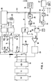
- FIGS. 4 to 6 largely corresponds to the first embodiment, so that only the differences are explained below. Components that have the same function in both exemplary embodiments are provided with the same reference symbols, so that only the differences or additional features are explained below.
- the electronic switching element T is connected to the inductor L and the other end of the inductor L is connected to one end of the two parallel circuit branches 12, 13. The other end of these circuit branches 12, 13 is connected to ground potential via the current sensor I designed as a low-resistance resistor 20.
- the electronic switches T 1 and T 4 are controlled by the control unit 15 via the control circuit 21 and the electronic switches T 2 and T 3 are controlled by the control unit 15 via the control circuit 22.
- a further transistor drive circuit 23 is connected between the output of the comparator 16 and the switching element T.
- the voltage generated at the current sensor I is present at the negative input of the comparator 16 and the reference signal U ref is fed to the positive input. This reference signal determines the value that the lamp current assumes.
- the ballast contains a signal generator 24, which in the present exemplary embodiment consists of four manually adjustable switches. A switch combination can be set at these switches in accordance with the respective power level to which the fluorescent lamp 14 belongs.
- a line leads from each of the switches of the signal generator 24 to the encoder 25.
- a further input of the encoder 25 is supplied with a signal VH, which is supplied by the control unit 15 and which indicates whether the ballast is in the preheating phase or not.
- the encoder 25 also has a sixth input, to which a signal M is supplied, which indicates whether a lamp circuit is on M indeststrom flows or not.
- the minimum current is a quiescent current that is maintained as long as the lamp 14 is inserted in the socket. It is a quiescent current through which the circuit is monitored and kept ready for operation. As long as the minimum current is not exceeded, the signal M is "ONE" and if the minimum current is exceeded, this signal is "ZERO".
- the encoder 25 generates from the supplied thereto six B inärsignalen a digital signal representing a measure of the instantaneous lamp current. This digital signal is fed to a digital / analog converter 26, which applies a corresponding analog signal to the A input of the multiplier 45.
- the minimum current signal M is generated by a differential amplifier 46, which receives a threshold signal 47 at one input and whose other input is connected to the output of the current sensor I.
- the encoder 25 consists, for example, of an encoding matrix. It is designed such that it forms a digital value from the output signal of the signal generator 24 and the signal VH, which indicates the size of the lamp current for the respective lamp type, both for the preheating phase and for the operating phase. However, this only applies as long as the signal M is "ZERO". If the signal M is "ONE”, then, regardless of the signal from the signal generator 24 and the signal VH, a very specific signal is output which corresponds to the size of the minimum current to be generated.
- a dimmer 27 is connected to the ballast.
- the digita The output signal of the dimmer 27 is fed via an optocoupler 28 in serial form to a series / parallel converter 29 which contains a shift register.
- the output signal of the series / parallel converter 29 is fed to the B input of the multiplier 45 via an encoder 30.
- Encoder 30 is blocked from passing signals when at least one of VH or M signals occurs. In this case, the signals from the dimmer 27 become ineffective. If the B input of multiplier 45 receives no signal, the signal applied to the A input is multiplied by a factor of 1.
- the analog signal A is multiplied by an analog value corresponding to the digital signal B.
- the signal B indicates the percentage of the lamp current from the nominal current. This percentage can be less than 100% or more than 100%. Fluorescent lamps can also be operated temporarily with a lamp current above the nominal current without being damaged.
- the dimmer 27 does not necessarily have to be manually adjustable. In the present exemplary embodiment, it is connected to a sensor MF, which, for example, determines the illuminance and supplies a corresponding control signal to the dimmer 27 in order to regulate this illuminance to a constant value.
- a sensor MF which, for example, determines the illuminance and supplies a corresponding control signal to the dimmer 27 in order to regulate this illuminance to a constant value.
- a timer or the like can also be used. be provided.
- the transmission behavior of the multiplier 45 is influenced by the signal of a temperature sensor TF, which is attached to the ballast. In this way, the lamp output can be reduced, for example, when the ballast temperature rises above a predetermined value.
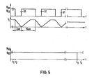
- the voltages U S1 , U S2 , U S3 and US 4 are the control voltages for the electronic switches T 1 to T 4 .
- a high voltage level means that the switch in question is controlled in the conductive state and a low voltage level means that the switch is blocked.
- the preheating phase which lasts a few hundred milliseconds, all four transistors T 1 to T 4 are conductive, so that the electrodes 14 1 and 14 2 are heated.
- the preheating phase ends at time t 1 .
- the control unit 15 then first controls the switch T 4 into the blocking state and a few microseconds later also switches T 1 .
- the circuit branch 13 was interrupted.
- the switch T 1 is blocked, the circuit branch 12 is additionally interrupted, so that no more current can flow through any of the electrodes.
- the inductance L strives to maintain the current flow and generates a high voltage which reaches the electrode 14 2 via T 2 , while the electrode 141 is connected to ground potential via T3 .
- the high voltage is above the first breakdown voltage of the switches T 1 and T 4 , so that the transistor with the lower breakdown voltage becomes conductive, although it is controlled in the blocking state.
- the breakdown voltage of T 1 or T4 thus corresponds to the ignition voltage for the fluorescent lamp.
- the inductance L can therefore discharge when the lamp is not ignited via T 1 and T 3 .
- FIG. 5 shows, numerous ignition pulses are generated in the ignition phase in order to periodically make T 1 and T 4 conductive and block them.
- the duration of each ignition pulse 31, in which T1 and T 4 are blocked, is 7 microseconds and the duration of the subsequent pulse pause, in which T 1 and T 4 are conductive, is approximately twice as long, 15 microseconds in the present exemplary embodiment.
- the period of the ignition pulses 31 is thus 22 microseconds.
- the second curve in FIG. 5 shows the course of the coil current i L through the inductance L. In the preheating phase, this current is at the value determined for preheating. If the switches T 1 and T 4 are blocked by an ignition pulse 31, then the coil current flowing through the switches T 1 and T 3 drops to zero. In the subsequent leading phase of T 1 and T 4 , the coil current rises again to the value specified by U ref . This value is maintained until the next firing pulse 31 occurs.
- the control unit 15 During each ignition process, the control unit 15 generates a certain number of control pulses 31 for, for example, 100 ignition pulses.
- the pulse pauses, in which T 1 and T 4 are conductive, are on the one hand so long that T 1 or T 4 can recover from the voltage breakdown in the conductive state, and on the other hand so short that there is no substantial recombination of the charge carriers in the fluorescent lamp 14 can.
- Due to the brief successive ignition pulses the gas in the fluorescent lamp is increasingly ionized until the ignition takes place. In this case, as is customary, a single ignition pulse is not generated, which must apply all of the ignition energy, but the ignition energy is distributed over a plurality of ignition pulses. This has the advantage that the value of the inductance L to a fraction of the otherwise usual value can be reduced.
- the control unit 15 delivers the full number of control pulses for e.g. 100 ignition pulses, regardless of when the ignition actually takes place. As a rule, only about 5 to 10 ignition pulses are required. The remaining ignition pulses are then generated when the fluorescent lamp is already lit, which is not detrimental to the operation.
- FIG. 5 shows the voltage and current profiles after the ignition. It is assumed that the switches T 1 and T 4 first become conductive immediately after the ignition, while the switches T 2 and T 3 block. In order to avoid cataphoresis on the lamp 14, the control unit 15 switches over the aforementioned switch pairs at predetermined time intervals. At the time t 3 , those switches T 2 and T 3 which were previously blocked are first switched to the conductive state. For a short period of time until time t 4 , all four switches are in the conductive state. Then the switches T 1 and T 4 , which were conductive in the previous phase, are controlled in the blocking state.
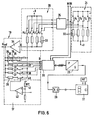
- the random generator 32 is provided in connection with the control unit 15 according to FIG.
- the random generator 32 randomly generates "ZERO" signals and "ONE" signals. It is controlled by the control pulses 31.
- the state of the output signal of the random generator 32 at the time of ignition of the fluorescent lamp determines which of the two switch pairs is initially switched on and which is off is switched. In this way it is avoided that the fluorescent lamp is always operated with the same polarity after being switched on.
- the random generator 32 replaces the integrator 18 according to FIG. 1.
- the signal generator 24 contains four switches S 1 , S 2 , S 3 , S 4 , which are each connected to one another at one end and connected to ground and the other ends of which are connected to the supply voltages via resistors 32 with different values. Each switch is connected to an input line of the encoder 25.
- the signals M and VH described above are at two further inputs of the encoder 25.
- the encoder 25 encodes the six-digit binary signal supplied to it into a four-digit binary signal which is fed to the digital / analog converter 26. Each of these signals controls an electronic switch A 1 , A 2 , A 3 ' A 4 . One end of these switches is connected to the supply voltage + U and the other ends are each connected to a weighted resistor 33. The ends of all resistors 33 are connected to one another and to the input of an inversion amplifier 34. This input also forms the A input of the multiplier 45.
- the amplifier 34 has several parallel feedback loops.
- the one feedback loop contains a series connection of several resistors 35, each of which can be bridged by a switch 36.
- the switches 36 are controlled by the various outputs of the encoder 30. When all switches 36 are closed, all resistors 35 are in first feedback branch ineffective.
- the amplifier 34 then has a gain factor of ONE. By opening one or more switches 36, the gain factor can be increased to over 100%.
- the first feedback branch consisting of the resistors 35 is connected in parallel to a plurality of further feedback branches, each of which consists of a weighted resistor 37 and a switch 38 connected in series therewith.
- the switches 38 are also controlled by output signals from the encoder 30. By closing one or more switches 38 (with switches 36 closed) the amplification factor of the amplifier 34 is reduced to below 100%.
- a third feedback branch of the amplifier 34 contains the series connection of a resistor 39 and a switch 40.
- the switch 40 is controlled by the temperature sensor TF, which reacts with an NTC resistor 41 to the temperature of the ballast.
- the amplifier 42 provides a signal to close the switch 40. This reduces the amplification factor of the amplifier 34, so that the reference voltage U ref at the output of this amplifier also decreases.
- the comparator 16 (Fig.4) is set to a lower lamp current.
- the signals for controlling each switch 36 and 38 are supplied from encoder 30 to the B input of multiplier 45.
- encoder 30 is disabled when either M or VH is "ONE".
- the switches 36 are closed and the switches 38 are open, ie the amplifier 34 has a gain factor of ONE, so that the reference chip Uref is set to the minimum current or the preheating current depending on which of the signals M or VH is "ONE". In this case, the lamp current cannot be influenced by the signals of the dimmer 27.
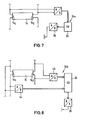
- Fig. 7 shows a modified embodiment with signal generator 24a.
- the signal transmitter is not set manually here, but rather generates the signal dependent on the lamp type or the lamp power automatically.
- the two electrodes 14 . and 14 2 of the fluorescent lamp 14 connected to the input of an analog / digital converter which generates a digital output signal which (with a defined lamp current) corresponds to the lamp resistance.
- This output signal is fed to the encoder 25, which forms a signal for generating the reference signal. Thanks to its lamp resistance, the fluorescent lamp ensures that the current corresponding to the lamp power is automatically set.
- the voltage drop at each of the two electrodes 14 1 or 14 2 is fed to an analog / digital converter 43 or 44.
- the voltage drop across the electrode corresponds to the electrode resistance.
- the output signals of the analog / digital converters 43 and 44 are converted in the signal generator 24b in the encoder 25 into a control signal which is further processed by the digital / analog converter 26 in the manner described above.
Landscapes
- Circuit Arrangements For Discharge Lamps (AREA)
Applications Claiming Priority (4)
| Application Number | Priority Date | Filing Date | Title |
|---|---|---|---|
| DE19853517297 DE3517297C1 (de) | 1985-05-14 | 1985-05-14 | Vorschaltgerät für Entladungslampen |
| DE3517297 | 1985-05-14 | ||
| DE19853524681 DE3524681A1 (de) | 1985-07-11 | 1985-07-11 | Dimmerschaltung fuer ein elektronisches leuchtstofflampen-vorschaltgeraet |
| DE3524681 | 1985-07-11 |
Publications (2)
| Publication Number | Publication Date |
|---|---|
| EP0201624A2 true EP0201624A2 (fr) | 1986-11-20 |
| EP0201624A3 EP0201624A3 (fr) | 1987-03-25 |
Family
ID=25832227
Family Applications (1)
| Application Number | Title | Priority Date | Filing Date |
|---|---|---|---|
| EP85111393A Withdrawn EP0201624A3 (fr) | 1985-05-14 | 1985-09-10 | Circuit ballast pour lampe fluorescente |
Country Status (1)
| Country | Link |
|---|---|
| EP (1) | EP0201624A3 (fr) |
Cited By (7)
| Publication number | Priority date | Publication date | Assignee | Title |
|---|---|---|---|---|
| EP0224301A3 (fr) * | 1985-11-19 | 1987-10-14 | Philips Patentverwaltung GmbH | Circuit pour le fonctionnement en courant alternatif de lampes à décharge |
| EP0323676A1 (fr) * | 1988-01-06 | 1989-07-12 | Koninklijke Philips Electronics N.V. | Dispositif électrique pour l'amorçage et l'alimentation d'une lampe à décharge dans le gaz |
| WO1992011742A1 (fr) * | 1990-12-17 | 1992-07-09 | Tunewell Transformers Limited | Procede et appareil permettant de faire fonctionner un tube a decharge lumineuse |
| EP0794692A2 (fr) | 1996-03-07 | 1997-09-10 | Heraeus Med GmbH | Circuit d'alimentation de lampes |
| DE19757295B4 (de) * | 1997-03-04 | 2005-08-04 | Tridonicatco Gmbh & Co. Kg | Elektronisches Vorschaltgerät |
| DE102008031409A1 (de) * | 2008-07-02 | 2010-01-07 | Tridonicatco Gmbh & Co. Kg | Erkennung des Typs einer an einem Betriebsgerät angeschlossenen Gasentladungslampe |
| DE19758987B4 (de) * | 1997-03-04 | 2017-02-23 | Tridonic Gmbh & Co Kg | Elektronisches Vorschaltgerät |
Family Cites Families (2)
| Publication number | Priority date | Publication date | Assignee | Title |
|---|---|---|---|---|
| US3999100A (en) * | 1975-05-19 | 1976-12-21 | Morton B. Leskin | Lamp power supply using a switching regulator and commutator |
| US4260932A (en) * | 1978-10-12 | 1981-04-07 | Vance Johnson | Method and circuit for facilitating the starting and steady state flickerless operation of a discharge lamp |
-
1985
- 1985-09-10 EP EP85111393A patent/EP0201624A3/fr not_active Withdrawn
Cited By (10)
| Publication number | Priority date | Publication date | Assignee | Title |
|---|---|---|---|---|
| EP0224301A3 (fr) * | 1985-11-19 | 1987-10-14 | Philips Patentverwaltung GmbH | Circuit pour le fonctionnement en courant alternatif de lampes à décharge |
| EP0323676A1 (fr) * | 1988-01-06 | 1989-07-12 | Koninklijke Philips Electronics N.V. | Dispositif électrique pour l'amorçage et l'alimentation d'une lampe à décharge dans le gaz |
| WO1992011742A1 (fr) * | 1990-12-17 | 1992-07-09 | Tunewell Transformers Limited | Procede et appareil permettant de faire fonctionner un tube a decharge lumineuse |
| EP0794692A2 (fr) | 1996-03-07 | 1997-09-10 | Heraeus Med GmbH | Circuit d'alimentation de lampes |
| DE19608819A1 (de) * | 1996-03-07 | 1997-09-11 | Heraeus Med Gmbh | Elektrische Versorgungs-Schaltung für Lampen |
| DE19608819C2 (de) * | 1996-03-07 | 1999-09-09 | Heraeus Med Gmbh | Elektrische Versorgungs-Schaltung für Lampen |
| DE19757295B4 (de) * | 1997-03-04 | 2005-08-04 | Tridonicatco Gmbh & Co. Kg | Elektronisches Vorschaltgerät |
| DE19758987B4 (de) * | 1997-03-04 | 2017-02-23 | Tridonic Gmbh & Co Kg | Elektronisches Vorschaltgerät |
| DE19758830B4 (de) * | 1997-03-04 | 2017-05-11 | Tridonic Gmbh & Co Kg | Elektronisches Vorschaltgerät |
| DE102008031409A1 (de) * | 2008-07-02 | 2010-01-07 | Tridonicatco Gmbh & Co. Kg | Erkennung des Typs einer an einem Betriebsgerät angeschlossenen Gasentladungslampe |
Also Published As
| Publication number | Publication date |
|---|---|
| EP0201624A3 (fr) | 1987-03-25 |
Similar Documents
| Publication | Publication Date | Title |
|---|---|---|
| DE3319739C2 (de) | Vorschaltgerät für Gasentladungslampen | |
| AT392384B (de) | Vorschaltgeraet zum betrieb von gasentladungslampen mit gleichstrom | |
| EP1114571A1 (fr) | Circuit pour faire fonctionner des lampes a decharge dans un gaz | |
| EP1333707A1 (fr) | Ballast électronique pour une lampe à décharge | |
| DE4413163A1 (de) | Schaltungsanordnung mit einem Wechselrichter | |
| EP0527137A1 (fr) | Procede et dispositf destines a reduire le courant d'entree lors de la mise en service d'une charge soumise a une inductance. | |
| DE3886000T2 (de) | Elektrische Anordnung zum Zünden und Speisen einer Gasenladungslampe. | |
| DE2657450C2 (de) | Speiseschaltung für einen Mikrowellengenerator und Verfahren zum Betrieb eines Mikrowellengenerators eines Mikrowellen-Erhitzungsgerätes | |
| DE2936063A1 (de) | Dimmerschaltkreis | |
| DE10138936A1 (de) | Einschalteinrichtung für eine Gasentladungslampe | |
| DE69029301T2 (de) | Anzündanordnung für eine entladungslampe | |
| DE3301108A1 (de) | Verfahren zum betreiben einer gasentladungslampe | |
| EP0399201B1 (fr) | Système d'alarme pour lumière de flash | |
| EP0201624A2 (fr) | Circuit ballast pour lampe fluorescente | |
| DE3227296A1 (de) | Pulsbreitenmodulatorschaltung | |
| DE69616451T2 (de) | Umschaltanordnung | |
| DE3517297C1 (de) | Vorschaltgerät für Entladungslampen | |
| EP0496040B1 (fr) | Ballast alternatif pour lampes à décharge | |
| DE4023253A1 (de) | Einrichtung zur speisung eines verbraucherzweipols mit einer weitgehend oberschwingungsfreien und dennoch rasch veraenderbaren gleichspannung oder einem weitgehend oberschwingungsfreien und dennoch rasch veraenderbaren gleichstrom | |
| DE3608362A1 (de) | Vorschaltgeraet fuer entladungslampen | |
| DE69315640T2 (de) | Verzögerungsmittel in einer Anlaufschaltung eines Vorschaltgerätes | |
| DE4108106A1 (de) | Verfahren und vorrichtung zur reduzierung des einschaltstromstosses beim betreiben einer induktivitaetsbehafteten last | |
| DE3607109C1 (en) | Ballast for discharge lamps | |
| DE3513365C2 (fr) | ||
| WO1985002749A1 (fr) | Montage de circuits pour le fonctionnement de lampes a decharge a basse tension a ultraviolet ou a substance fluorescente |
Legal Events
| Date | Code | Title | Description |
|---|---|---|---|
| PUAI | Public reference made under article 153(3) epc to a published international application that has entered the european phase |
Free format text: ORIGINAL CODE: 0009012 |
|
| AK | Designated contracting states |
Kind code of ref document: A2 Designated state(s): AT BE CH DE FR GB IT LI LU NL SE |
|
| PUAL | Search report despatched |
Free format text: ORIGINAL CODE: 0009013 |
|
| AK | Designated contracting states |
Kind code of ref document: A3 Designated state(s): AT BE CH DE FR GB IT LI LU NL SE |
|
| 17P | Request for examination filed |
Effective date: 19870502 |
|
| 17Q | First examination report despatched |
Effective date: 19890428 |
|
| STAA | Information on the status of an ep patent application or granted ep patent |
Free format text: STATUS: THE APPLICATION IS DEEMED TO BE WITHDRAWN |
|
| 18D | Application deemed to be withdrawn |
Effective date: 19910213 |
|
| RIN1 | Information on inventor provided before grant (corrected) |
Inventor name: HASEMANN, FRED, DR.-ING. Inventor name: WITTIG, NORBERT, DIPL.-ING. Inventor name: MERTENS, FERDINAND, DIPL.-ING. |