EP0201629A2 - Procédé et appareil de cristallisation continue par évaporation pour la préparation du sucre - Google Patents
Procédé et appareil de cristallisation continue par évaporation pour la préparation du sucre Download PDFInfo
- Publication number
- EP0201629A2 EP0201629A2 EP85114973A EP85114973A EP0201629A2 EP 0201629 A2 EP0201629 A2 EP 0201629A2 EP 85114973 A EP85114973 A EP 85114973A EP 85114973 A EP85114973 A EP 85114973A EP 0201629 A2 EP0201629 A2 EP 0201629A2
- Authority
- EP
- European Patent Office
- Prior art keywords
- suspension
- chamber
- flow
- heating
- treatment room
- Prior art date
- Legal status (The legal status is an assumption and is not a legal conclusion. Google has not performed a legal analysis and makes no representation as to the accuracy of the status listed.)
- Granted
Links
Images

Classifications
-
- C—CHEMISTRY; METALLURGY
- C13—SUGAR INDUSTRY
- C13B—PRODUCTION OF SUCROSE; APPARATUS SPECIALLY ADAPTED THEREFOR
- C13B30/00—Crystallisation; Crystallising apparatus; Separating crystals from mother liquors ; Evaporating or boiling sugar juice
- C13B30/02—Crystallisation; Crystallising apparatus
- C13B30/022—Continuous processes, apparatus therefor
Definitions
- the invention relates to a process for continuous evaporation crystallization in a suspension for the extraction of sugar consisting of juice and crystals, in which concentrated feed dissolution and crystal base magma are continuously fed into a first treatment room and product magma are continuously withdrawn from the last treatment room, the suspension being successively used by several separate round treatment rooms are passed through and placed in each treatment room with simultaneous supply of heat in an internal circulation flow and level-controlled from the individual treatment rooms to the next following treatment room.
- the invention further relates to a device for carrying out such a method with treatment rooms which are arranged one above the other as separate cylindrical apparatus chambers, a tapering chamber bottom tapering downwards, a heating medium through which a heating medium flows with cross sections through which the suspension can flow, and devices for removing the Brüdens and for transferring the suspension from the upper to the lower apparatus chamber.
- each apparatus chamber is designed according to the agitator boilers for the discontinuous crystallization.
- a heating chamber with radially external heating elements, a central guide tube and an agitator held in the bottom are provided above the chamber floor.
- the agitators of the apparatus chamber through which the first flow passes are designed as high-speed mixing stirrers, while the agitators of the subsequent chambers are designed as low-speed circulation stirrers.
- the chambers there are level controls for leveling the level just above the heating chamber.
- the high-speed mixing stirrers cause highly turbulent shear fields and a visible circulation flow, while the low-speed stirrers only lead to an essentially laminar circulation flow.
- the suspension is kept in a concentric ring circulation flow in all apparatus chambers with the intake juice being fed in on the suction side.
- the suspension is withdrawn from the individual treatment rooms on the pressure side and fed to the next treatment room on the suction side.
- an inlet pipe opening out above the stirrer of the respective apparatus chamber is connected to a feed line via a control valve.
- a suspension discharge pipe equipped with a control valve or a control flap is provided and connected to a suspension supply pipe of the next chamber.
- the control valve of the feed pipe for the intake juice are equipped with a sensor arranged in the associated apparatus chamber to determine the toughness, electrical conductivity, density or boiling point increase of the suspension and the control valve or the control flap of the suspension drain pipe with one in the same apparatus chamber just above the Heating device arranged level sensor or switch connected.
- the object of the invention is to improve the method explained at the outset with regard to the suspension residence time distribution and to simplify the device for carrying out the method.
- This object is achieved in that the suspension is guided in each treatment room by forced guidance on an approximately horizontal circular path and at the same time exerts a trombone-shaped circular movement from the outside inwards, the circular movement by feeding in further suspension and by utilizing the mammoth occurring in the heating area -Pump effect is generated.
- suspension on the positively guided circular path is also alternately guided upwards and downwards, so that a wave-shaped flow pattern is formed which is closed to form a circular ring.
- the overhead line of the suspension from one treatment room to the next treatment room can take place in the free overflow;
- the level of the suspension in each treatment room can be regulated by controlling the overflow height.
- syrup can also be fed into at least some treatment rooms in a controlled manner.
- each apparatus chamber comprises a plurality of heating chambers which are arranged in the circumferential direction at the same angular distance from one another and which are partitioned off from one another with respect to their cross-sections through which the suspension flows, via partitions, however, via defined flow cross-sections in the circumferential direction are in flow connection with one another, which form a forced guide for the suspension in the circumferential direction, the first heating chamber, seen in the flow direction of the suspension, having a suspension inlet and the last heating chamber having a suspension overflow that corresponds to the suspension inlet the apparatus chamber underneath is connected.
- each apparatus chamber is arranged around a central guide tube which is open at the top and bottom and is divided by the partition walls mentioned into segments which are closed on the jacket side and on the bottom side only with the associated heating chamber for the suspension in a flow-exchanging connection stand.
- a partition wall alternately projects above the maximum suspension level between two heating chambers, but has a suspension circulation opening below the heater above the conical chamber floor, while the partition wall following in the flow direction of the suspension has an upper overflow into the has the following heating chamber and seals the bottom of the chamber in a flow-tight manner.
- each apparatus chamber is structurally particularly simple and basically does not require any control. It is particularly advantageous that the desired flow circulation of the Suspension is achieved without agitators or other powered stirring or mixing tools. However, since the flowability of the suspension is getting worse from top to bottom, it can be advantageous, depending on the consistency of the suspension, to provide driven stirring or mixing tools in the bottom apparatus chamber or in the bottom apparatus chambers, e.g. the two bottom chambers, e.g. can be designed as a lifting system according to the device as described in German patent application P 35 17 511.7-41. Such a lifting system would serve to support the mammoth pump effect. ;
- the superimposed apparatus chambers can be connected to one another.
- the vapor is then drawn off via a juice separator on the top chamber of the apparatus.
- the vapors are fed to a condenser and the non-condensable gases to a water ring pump.
- the atmosphere in the vapors is under atmospheric pressure.
- the suspension transfer from one apparatus chamber to the other would then have to take place via a lock! With this mode of operation, the apparatus chambers would have to be operated with different vapor pressures.
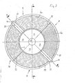
- FIG. 1 of the illustrated Verdampfungskristallisa- tio n storm consists of separate, stacked cylindrical apparatus chambers 1, the number of which is apparent from the amount to be produced magma consists.
- Each apparatus chamber 1 has a chamber floor 2 which tapers downwards in a conical shape and is provided with a central flow cone 3, which at the same time forms a chimney hood for a vapor outlet, which merges upwards into a perpendicular central vapor tube 4. Only in the lowest apparatus chamber is one such vapor deduction is not provided.
- the apparatus chambers 1 can be connected to one another on the vapor side.
- the vapor is then drawn off via a juice separator 5 on the upper apparatus chamber 1; in this embodiment there is then the same pressure in all apparatus chambers 1.
- the vapors are fed to a condenser, not shown, the non-condensable gases to a water ring pump, also not shown.
- the atmosphere in the vapors is under atmospheric pressure.
- each apparatus chamber 1 there is also a heater 6 through which a heating medium, preferably steam, flows and which is arranged around a central guide tube 7 open at the top and bottom, the upper edge of which is flush with the upper edge of the Heating 6 lies.
- the heater 6 of each apparatus chamber 1 comprises four heating chambers 8, 9, 10, 11 arranged in the circumferential direction at the same angular distance from one another, each of which is limited by radially arranged partition walls 12, the vapor tube 4, the flow cone 3, the chamber bottom 2 and the jacket of the corresponding ones Apparatus chamber 1.
- the partition walls 12 mentioned divide the guide tube 7 into segments 13, which are closed on the shell side by the vapor tube 4, the guide tube 7 and the partition walls 12 and on the bottom side are only in flow-exchanging connection with the associated heating chamber 8-10.
- the heater 6 consists of concentrically spaced double-walled ring segments 6a, which are connected to each other in terms of flow and are associated with diametrically opposed hollow partition walls 12 and have a steam inlet 14.
- a valve-controlled inlet 16 for concentrated feed dissolution (syrup) and a further valve-controlled inlet 17 for crystal-foot magma are provided in the uppermost apparatus chamber 1. Both inlets 16, 17 open into a suspension inlet 18 at the beginning of the first heating chamber 8, from where the suspension flows in a forced flow through the four heating chambers 8-11 in succession, and then via a suspension overflow provided in the last heating chamber 11 19 to get into the suspension inlet 18 of the apparatus chamber 1 below.
- the suspension level 20 is set in each apparatus chamber 1 by overflow flaps 21.
- the ring segments 6a between them have cross sections through which the suspension flows and which are partitioned off from the adjacent heating chamber 8-11 by the partition walls 12 mentioned.
- the separating wall 12 between the heating chambers 8 and 9 seen in the flow direction of the suspension also projects above the maximum suspension level 20, but is at a clear distance from the chamber bottom 2, forming a suspension circulation opening 22, while the downstream one seen in the flow direction of the suspension is the
- the heating chamber 9 separating the heating chamber 10 from the partition wall 12 is connected to the chamber bottom 2 in a flow-tight manner, but for the suspension has an upper overflow 23 into the subsequent heating chamber 10.
- the partition 12 that then follows between the heating chambers 10 and 11 corresponds in its design to the partition between the heating chambers 8 and 9.
- the suspension formed from the two inlets 16, 17 thus flows downward from the suspension inlet 18 between the ring segments 6a of the first heating chamber 8 in order to pass through the suspension circulation opening 22 of the partition wall 12 into the subsequent heating chamber 9, where the suspension flows upwards between the ring segments 6a and reaches the heating chamber 10 via the overflow 23, from which in turn flows through the suspension circulation opening 22 at the bottom into the last heating chamber 11, from which the suspension then flows via the suspension overflow 19 arrives in the suspension inlet 18 of the apparatus chamber 1 underneath.
- the suspension is therefore positively guided on a circular path and alternately directed upwards and downwards on this circular path, so that a wavy flow closed to form a circular ring results course. This flow occurs and is maintained by the continuously fed syrup and the continuously fed crystal foot magma.
- a valve-controlled feed line 24 for additional syrup opens into the suspension inlet 18 of each apparatus chamber 1 and, depending on the magma consistency, is fed into the inlet of each apparatus chamber 1 in a controlled manner. After the suspension has passed through all the apparatus chambers 1 from top to bottom, the product magma is drawn off on the chamber bottom 2 of the lowest apparatus chamber 1 via an outlet 25.
- Figure 1 shows circumferentially offset longitudinal sections for the individual apparatus chambers 1.
- a partition wall 12 is shown with an overflow 23 corresponding to the partition wall between the heating chambers 9 and 10, while the second and bottom apparatus chamber partition walls 12 according to the partition walls between the heating chambers 8 and 9 and 10, respectively and 11 show.
Landscapes
- Chemical & Material Sciences (AREA)
- Crystallography & Structural Chemistry (AREA)
- Life Sciences & Earth Sciences (AREA)
- Biochemistry (AREA)
- Organic Chemistry (AREA)
- Confectionery (AREA)
- Heat-Exchange Devices With Radiators And Conduit Assemblies (AREA)
- Organic Low-Molecular-Weight Compounds And Preparation Thereof (AREA)
Applications Claiming Priority (2)
| Application Number | Priority Date | Filing Date | Title |
|---|---|---|---|
| DE19853517511 DE3517511A1 (de) | 1985-05-15 | 1985-05-15 | Kuehlungskristallisationsturm fuer zucker-magma |
| DE3517511 | 1985-05-15 |
Publications (3)
| Publication Number | Publication Date |
|---|---|
| EP0201629A2 true EP0201629A2 (fr) | 1986-11-20 |
| EP0201629A3 EP0201629A3 (en) | 1988-08-24 |
| EP0201629B1 EP0201629B1 (fr) | 1990-09-19 |
Family
ID=6270802
Family Applications (1)
| Application Number | Title | Priority Date | Filing Date |
|---|---|---|---|
| EP85114973A Expired - Lifetime EP0201629B1 (fr) | 1985-05-15 | 1985-11-26 | Procédé et appareil de cristallisation continue par évaporation pour la préparation du sucre |
Country Status (2)
| Country | Link |
|---|---|
| EP (1) | EP0201629B1 (fr) |
| DE (2) | DE3517511A1 (fr) |
Cited By (5)
| Publication number | Priority date | Publication date | Assignee | Title |
|---|---|---|---|---|
| EP0403441A3 (fr) * | 1989-06-14 | 1991-02-06 | ERIDANIA ZUCCHERIFICI NAZIONALI S.p.A. | Procédé et appareil pour le grossissement continu de cristaux préformés des massecuites |
| WO2001091875A1 (fr) * | 2000-06-01 | 2001-12-06 | The Tongaat-Hulett Group Limited | Appareil de cuisson a vide continu |
| WO2003016576A1 (fr) * | 2001-08-14 | 2003-02-27 | Bruce Stclair Moor | Appareil de cristallisation par evaporation continue |
| WO2007113849A1 (fr) * | 2006-03-30 | 2007-10-11 | Spray Engineering Devices Limited | Cuve a vide verticale continue amelioree |
| WO2010038160A2 (fr) | 2008-10-01 | 2010-04-08 | Tongaat Hulett Limited | Cuiseur sous vide en continu |
Families Citing this family (3)
| Publication number | Priority date | Publication date | Assignee | Title |
|---|---|---|---|---|
| IT1208242B (it) * | 1987-02-11 | 1989-06-12 | Eridania | Procedimento e dispositivo per la cristallizzazione di massecotte di media e bassa purezza |
| CN106512461B (zh) * | 2016-11-30 | 2019-04-12 | 江苏润普食品科技股份有限公司 | 一种粒状丙酸钙的低温蒸发结晶装置及工艺 |
| DE102019123903B4 (de) * | 2019-09-05 | 2023-01-12 | Bma Braunschweigische Maschinenbauanstalt Ag | Kühlungskristallisator und Verfahren zur Zuckerkristallisation |
Family Cites Families (7)
| Publication number | Priority date | Publication date | Assignee | Title |
|---|---|---|---|---|
| DE971480C (de) * | 1955-07-29 | 1959-02-05 | Ernst Dr Lange | Mehrgliedriger Verdampfer mit senkrecht stehenden Heizrohren fuer die Zuckerindustrie |
| DE1054065B (de) * | 1958-05-08 | 1959-04-02 | Buckau Wolf Maschf R | Ringheizkammer mit Stufenschaltung fuer Vakuumkocher |
| FR1486046A (fr) * | 1966-07-06 | 1967-06-23 | Lang Gepgyar | Appareil de concentration sous vide |
| ZA775459B (en) * | 1977-09-12 | 1979-02-28 | Huletts Sugar | Improvements in continuous vacuum crystallisers |
| DE3120732A1 (de) * | 1981-05-25 | 1982-12-09 | Erich Prof. Dr. 3340 Wolfenbüttel Reinefeld | "verfahren und vorrichtung zur kontinuierlichen verdampfungskristallisation" |
| DE3203141C2 (de) * | 1982-01-30 | 1983-12-01 | Salzgitter Maschinen Und Anlagen Ag, 3320 Salzgitter | Verfahren und Vorrichtung zur Kühlung von Zuckerfüllmasse in einer Vertikalmaische |
| DE3336112C1 (de) * | 1983-10-05 | 1985-03-07 | Selwig & Lange GmbH, 3300 Braunschweig | Vertikalkühlmaische für Zuckermagma mit vertikal oszillierenden Rührelementen |
-
1985
- 1985-05-15 DE DE19853517511 patent/DE3517511A1/de active Granted
- 1985-11-26 DE DE8585114973T patent/DE3579811D1/de not_active Expired - Fee Related
- 1985-11-26 EP EP85114973A patent/EP0201629B1/fr not_active Expired - Lifetime
Cited By (11)
| Publication number | Priority date | Publication date | Assignee | Title |
|---|---|---|---|---|
| EP0403441A3 (fr) * | 1989-06-14 | 1991-02-06 | ERIDANIA ZUCCHERIFICI NAZIONALI S.p.A. | Procédé et appareil pour le grossissement continu de cristaux préformés des massecuites |
| WO2001091875A1 (fr) * | 2000-06-01 | 2001-12-06 | The Tongaat-Hulett Group Limited | Appareil de cuisson a vide continu |
| US6991708B2 (en) | 2000-06-01 | 2006-01-31 | The Tongaat-Hulett Group Limited | Continuous vacuum pan |
| WO2003016576A1 (fr) * | 2001-08-14 | 2003-02-27 | Bruce Stclair Moor | Appareil de cristallisation par evaporation continue |
| US7195674B2 (en) | 2001-08-14 | 2007-03-27 | Moor Bruce Stclair | Continuous pan crystallizer |
| WO2007113849A1 (fr) * | 2006-03-30 | 2007-10-11 | Spray Engineering Devices Limited | Cuve a vide verticale continue amelioree |
| EA013155B1 (ru) * | 2006-03-30 | 2010-02-26 | Спрей Энджиниринг Дивайсиз Лимитед | Усовершенствованный вертикальный вакуум-выпарной аппарат непрерывного действия |
| AU2006341267B2 (en) * | 2006-03-30 | 2010-12-09 | Spray Engineering Devices Limited | Improved vertical continuous vacuum pan |
| US7972445B2 (en) | 2006-03-30 | 2011-07-05 | Spray Engineering Devices Limited | Vertical continuous vacuum pan |
| WO2010038160A2 (fr) | 2008-10-01 | 2010-04-08 | Tongaat Hulett Limited | Cuiseur sous vide en continu |
| WO2010038160A3 (fr) * | 2008-10-01 | 2010-10-28 | Tongaat Hulett Limited | Cuiseur sous vide en continu |
Also Published As
| Publication number | Publication date |
|---|---|
| DE3517511A1 (de) | 1986-11-20 |
| DE3579811D1 (de) | 1990-10-25 |
| DE3517511C2 (fr) | 1988-11-24 |
| EP0201629A3 (en) | 1988-08-24 |
| EP0201629B1 (fr) | 1990-09-19 |
Similar Documents
| Publication | Publication Date | Title |
|---|---|---|
| DE2215107A1 (de) | Verfahren zur Behandlung von Flüssigkeiten, insbesondere zur Behandlung von Wasser, und Vorrichtung zur Durchführung des Verfahrens | |
| EP0201629B1 (fr) | Procédé et appareil de cristallisation continue par évaporation pour la préparation du sucre | |
| EP0065775B1 (fr) | Procédé et appareil pour la cristallisation en continu par évaporation | |
| DE3008250C2 (de) | Rührwerks-Flotationszelle | |
| DE1442629C3 (de) | Vorrichtung zur Durchführung von Aufschlußverfahren durch Naßbehandlung | |
| DE2760246C2 (de) | Apparat zur Flotationsabscheidung von Feststoffpartikeln aus einer Flüssigkeit | |
| CH677616A5 (fr) | ||
| CH667879A5 (de) | Fermentationsanlage. | |
| DE2320859A1 (de) | Verfahren und einrichtung zur herbeifuehrung von partikelwachstum in einer stroemenden fluessigkeitssuspension | |
| DE1421310B2 (de) | Verfahren und Vorrichtung zum Abscheiden von Staubteilchen aus einem Gasstrom | |
| EP0312863B1 (fr) | Installation de décaféination en continu de café vert | |
| CH640423A5 (de) | Stoffaustauschvorrichtung, insbesondere fuer die extraktion. | |
| DE69619276T2 (de) | Verfahren und anlage zum mischen und trennen von zwei nicht mischbahren flüssigkeiten | |
| DE2543898A1 (de) | Verfahren zum sammeln und gleichzeitigen trennen einer fluessigkeit und eines gases | |
| AT395861B (de) | Verfahren und vorrichtung zum kristallisieren von fuellmassen niedriger und mittlerer reinheit | |
| DE1922982C3 (de) | Vorrichtung zur Wasseraufbereitung mittels einer Mehrspalt-Klärvorrichtung | |
| DE3401161C2 (fr) | ||
| DE3529983A1 (de) | Verdampfer | |
| DE3536321C2 (fr) | ||
| DE3346078C1 (de) | Vorrichtung zur kontinuierlichen Herstellung von KonfitÜren oder Marmeladen | |
| DE1254589B (de) | Kontinuierlich arbeitender Verdampfungs-Kristallisator | |
| DE2348844A1 (de) | Dekanter | |
| DE3203524A1 (de) | Kuehlmaische | |
| DE1458765C (de) | Verfahren zur Reduktion von Eisenoxyden und Vorrichtung zur Durchführung des Verfahrens | |
| DE112172C (fr) |
Legal Events
| Date | Code | Title | Description |
|---|---|---|---|
| PUAI | Public reference made under article 153(3) epc to a published international application that has entered the european phase |
Free format text: ORIGINAL CODE: 0009012 |
|
| AK | Designated contracting states |
Kind code of ref document: A2 Designated state(s): DE FR IT NL |
|
| PUAL | Search report despatched |
Free format text: ORIGINAL CODE: 0009013 |
|
| AK | Designated contracting states |
Kind code of ref document: A3 Designated state(s): DE FR IT NL |
|
| 17P | Request for examination filed |
Effective date: 19880719 |
|
| RAP1 | Party data changed (applicant data changed or rights of an application transferred) |
Owner name: BRAUNSCHWEIGISCHE MASCHINENBAUANSTALT AG |
|
| 17Q | First examination report despatched |
Effective date: 19890825 |
|
| GRAA | (expected) grant |
Free format text: ORIGINAL CODE: 0009210 |
|
| AK | Designated contracting states |
Kind code of ref document: B1 Designated state(s): DE FR IT NL |
|
| REF | Corresponds to: |
Ref document number: 3579811 Country of ref document: DE Date of ref document: 19901025 |
|
| ITF | It: translation for a ep patent filed | ||
| ET | Fr: translation filed | ||
| PG25 | Lapsed in a contracting state [announced via postgrant information from national office to epo] |
Ref country code: NL Effective date: 19910601 |
|
| NLV4 | Nl: lapsed or anulled due to non-payment of the annual fee | ||
| PLBE | No opposition filed within time limit |
Free format text: ORIGINAL CODE: 0009261 |
|
| STAA | Information on the status of an ep patent application or granted ep patent |
Free format text: STATUS: NO OPPOSITION FILED WITHIN TIME LIMIT |
|
| 26N | No opposition filed | ||
| PGFP | Annual fee paid to national office [announced via postgrant information from national office to epo] |
Ref country code: FR Payment date: 19910930 Year of fee payment: 7 |
|
| PGFP | Annual fee paid to national office [announced via postgrant information from national office to epo] |
Ref country code: DE Payment date: 19911106 Year of fee payment: 7 |
|
| ITTA | It: last paid annual fee | ||
| PG25 | Lapsed in a contracting state [announced via postgrant information from national office to epo] |
Ref country code: FR Effective date: 19930730 |
|
| PG25 | Lapsed in a contracting state [announced via postgrant information from national office to epo] |
Ref country code: DE Effective date: 19930803 |
|
| REG | Reference to a national code |
Ref country code: FR Ref legal event code: ST |