EP0201630A2 - Revêtement de façade par des éléments à double parois avec ventilation arrière - Google Patents
Revêtement de façade par des éléments à double parois avec ventilation arrière Download PDFInfo
- Publication number
- EP0201630A2 EP0201630A2 EP85115462A EP85115462A EP0201630A2 EP 0201630 A2 EP0201630 A2 EP 0201630A2 EP 85115462 A EP85115462 A EP 85115462A EP 85115462 A EP85115462 A EP 85115462A EP 0201630 A2 EP0201630 A2 EP 0201630A2
- Authority
- EP
- European Patent Office
- Prior art keywords
- leg
- facade
- vertical
- edge section
- facade elements
- Prior art date
- Legal status (The legal status is an assumption and is not a legal conclusion. Google has not performed a legal analysis and makes no representation as to the accuracy of the status listed.)
- Granted
Links
Images

Classifications
-
- E—FIXED CONSTRUCTIONS
- E04—BUILDING
- E04F—FINISHING WORK ON BUILDINGS, e.g. STAIRS, FLOORS
- E04F13/00—Coverings or linings, e.g. for walls or ceilings
- E04F13/07—Coverings or linings, e.g. for walls or ceilings composed of covering or lining elements; Sub-structures therefor; Fastening means therefor
- E04F13/08—Coverings or linings, e.g. for walls or ceilings composed of covering or lining elements; Sub-structures therefor; Fastening means therefor composed of a plurality of similar covering or lining elements
- E04F13/0801—Separate fastening elements
- E04F13/0803—Separate fastening elements with load-supporting elongated furring elements between wall and covering elements
- E04F13/081—Separate fastening elements with load-supporting elongated furring elements between wall and covering elements with additional fastening elements between furring elements and covering elements
- E04F13/0814—Separate fastening elements with load-supporting elongated furring elements between wall and covering elements with additional fastening elements between furring elements and covering elements fixed by means of clamping action
-
- E—FIXED CONSTRUCTIONS
- E04—BUILDING
- E04F—FINISHING WORK ON BUILDINGS, e.g. STAIRS, FLOORS
- E04F13/00—Coverings or linings, e.g. for walls or ceilings
- E04F13/07—Coverings or linings, e.g. for walls or ceilings composed of covering or lining elements; Sub-structures therefor; Fastening means therefor
- E04F13/08—Coverings or linings, e.g. for walls or ceilings composed of covering or lining elements; Sub-structures therefor; Fastening means therefor composed of a plurality of similar covering or lining elements
- E04F13/12—Coverings or linings, e.g. for walls or ceilings composed of covering or lining elements; Sub-structures therefor; Fastening means therefor composed of a plurality of similar covering or lining elements of metal or with an outer layer of metal or enameled metal
-
- E—FIXED CONSTRUCTIONS
- E04—BUILDING
- E04F—FINISHING WORK ON BUILDINGS, e.g. STAIRS, FLOORS
- E04F2201/00—Joining sheets or plates or panels
- E04F2201/05—Separate connectors or inserts, e.g. pegs, pins, keys or strips
- E04F2201/0511—Strips or bars, e.g. nailing strips
Definitions
- the invention relates to a facade cladding made of ventilated bowl-shaped facade elements, in particular sheet metal shells, with fastening means for holding the facade elements.
- the fastening means are located in the vertical joint area of the facade elements.
- a substructure is usually attached to the wall of the building, which has vertical U-profiles running through in the area of the vertical joints. Bores are formed in the side legs of these U-profiles, in which suspension bolts are mounted.
- the sheet metal shells are suspended one after the other from below upwards via these suspension bolts, for which purpose corresponding punched-out holes are formed in the side legs of the sheet metal shells, which are hung over the suspension bolts.
- the known facade cladding of this type have considerable disadvantages.
- the side parts of the sheet metal shells must be made relatively wide, so that a stable material area remains on both sides of the cut-outs. Nevertheless, the punched holes weaken the side parts so that undesired deformations can occur in the side area when the sheet metal shells are transported.
- the production of the punching is associated with a relatively high amount of work, which increases the manufacturing costs of the sheet metal shells.
- the invention has for its object to improve a facade cladding of the type mentioned in such a way that the disadvantages mentioned above are avoided, the manufacture of the facade elements and the support structure provided for their attachment and the assembly process of the facade cladding should be considerably simplified, while effective ventilation of the facade cladding is ensured.
- the facade elements are no longer suspended in the area of the vertical joints, but in the horizontal joint area of the facade elements.
- the facade elements in particular formed by sheet metal shells, no longer have any punched-outs for engaging suspension bolts, so that the manufacture of the sheet metal shells is simplified.
- the side area of the sheet metal shells is thus not weakened, so that no deformations occur there when the sheet metal shells are transported.
- the fasteners have supports for absorbing the vertical forces and separate holding devices for absorbing the horizontal forces of the facade elements.
- the division of the fasteners into supports that absorb only vertical forces and the holding devices that absorb the wind forces has proven to be particularly favorable for assembly.
- a support and a holding device are arranged in each of the two lateral edge areas of the horizontal joint area between two facade elements arranged one above the other.
- the upper edge section of the facade elements in vertical section has an L-shape with a leg which is angled horizontally inwards and a leg which extends vertically upwards, while the lower edge section has a U-shape with a leg which runs horizontally inwards and then has a leg bent vertically upwards, the two legs of the upper edge section being longer than those of the lower edge section.
- the leg of the upper sheet metal shell which runs vertically upwards overlaps in the installed position with the upper edge region of the vertical leg of the lower sheet metal shell.
- the horizontal leg of the upper edge section of the facade elements rests on the supports, while its upper vertical leg and the vertical leg of the lower edge region of the facade element arranged above each engage in the holding devices.
- the supports absorb the entire vertical loads from the facade elements, while the holding devices hold both the lower edge section of the respective upper and the upper edge section of the associated lower facade element immovably against horizontal movement.
- the supports and the holding devices are advantageously guided with guide sections in vertical guide rails, the supports being fixed in height in the guide rails, while the holding devices are vertically displaceable in the guide rails.
- the supports can thus safely transfer the vertical loads absorbed onto the guide rails, while the holding devices in the guide rails may be vertically displaceable, since they only absorb horizontal forces.
- the holding devices are guided in the guide rails so that they cannot be pulled out of them by the horizontal forces that occur.
- the vertical displaceability of the holding means in the guide rails leads to a considerable simplification of the Montagevorgan g it.
- the guide rails can have cutouts for receiving the guide sections of the supports, the guide sections in the installed position resting with shoulders on the projections of the guide rails formed by the cutouts. These punchings can be made after the assembly of the guide rails or the substructure on the construction site, which then fixes the position of the horizontal joints in the facade.
- the supports are formed by angle or profile pieces, the vertical leg of which is arranged as a guide section in the guide rail. In the horizontal leg of the elbows, a slightly protruding cushion made of an elastic material can be arranged, whereby a noise in the case of egg ner movement of the sheet metal shell is avoided. Instead of an angle or profile piece, a correspondingly dimensioned screw can also be fastened to the guide rail.
- the invention proposes that the holding devices have downwardly open vertical grooves for receiving the legs of the facade elements, the holding devices respectively resting on the vertical leg of the upper edge section of the facade elements, while between the vertical leg of the lower edge section of the facade elements and the associated groove base as well as a play remains between the horizontal leg of the lower edge section and the holding device. If a sheet metal shell is placed on the two bearings provided for the assembly of the facade elements, the two associated holding devices are pushed down onto the vertical leg of the sheet metal shell. The sheet metal shell to be arranged above can then be hooked into the front groove with its lower vertical leg and pushed onto the upper support.
- the holding devices are each provided with an auxiliary screw for canceling the slot play in the guide rail, this brake screw being able to be arranged in such a way that it is put on after installation the holding device is accessible from the outside on the vertical web of the respective lower sheet metal shell.
- the holding devices are moved upwards via the vertical joints using suitable tools, which can be carried out without any problems, since the vertical edge sections of the facade elements that are angled inwards do not match the U-profiles of the substructure overlap.
- the vertical leg of the upper edge section of the facade elements can be fastened in the holding device by means of a screw. This measure represents an additional security against unintentional release of the sheet metal shells from the holding devices.
- the supports and the holding devices are expediently made of aluminum.
- the facade elements can be held approximately halfway up by intermediate brackets also guided in the guide rails. This measure is particularly appropriate when the sheet metal shells have a relatively large height.
- the intermediate brackets Like the holding devices arranged in the horizontal joints, the intermediate brackets only absorb horizontal forces that are primarily caused by wind.
- the arrangement is expediently such that the intermediate brackets each have a vertical groove which is open toward the underside and into which one leg of an angle attached to the facade element is received.
- the intermediate bracket like the holding devices arranged in the horizontal joints, is moved downward in its guide rail after the facade element has been placed on the support until it lies on the associated angle.
- the intermediate bracket can also with egg ner be provided inside its groove elastic base cord.
- An angle for receiving an intermediate bracket can be attached to each of the vertical edge sections of the facade elements that are angled inward.
- the guide rails can be fastened to a substructure of the holding structure.
- the guide rails are expediently attached to the two outer sides of a continuous vertical U-profile of the substructure. These vertical U-profiles practically close the vertical joints.
- the guide rails advantageously have essentially the shape of a U-profile, the opening of which is partially closed by short webs on both sides.
- the short webs can then be punched out to accommodate the guide sections of the supports in the guide rails at a fixed height, so that window cutouts are formed, into which the guide sections can be inserted.
- the supports or holding devices can be fastened directly to the wall of the building without arranging a substructure or to the window structures.
- the sheet metal shells advantageously have on one of the angled vertical edge sections a web pointing in the direction of the joint or away from it, which is encompassed by the sealing profile for holding it.
- This web is expediently on the free edge of the angled vertical edge section attached so that the elastic sealing profile claw-like encompasses the web and possibly the adjacent edge section of a facade element, while the sealing profile with its other edge section rests under a certain prestress on the angled edge section of the other sheet metal shell.
- the above-described holding structure for the facade elements enables the entire substructure profiles with all the necessary fastening grooves to be assembled and aligned without prior processing.
- the horizontal joint course is fixed and the supports can be hooked in at the same time by punching out the guide rails.
- the facade elements can be partially suspended from top to bottom or from bottom to top depending on the needs of the construction process and can only be attached by vertically moving the holding devices.
- the facade elements are reliably secured against unhinging.
- the sheet metal shells do not need punchings for their attachment and fastening, so that their processing only extends to the shaping needs. Due to their special suspension, the sheet metal shells only require a small depth of the horizontal and vertical folds, so that the facade elements can be made relatively flat overall.
- the upper edge section of the facade elements - as in the embodiment described above - has an L-shape in vertical section with a horizontally inwardly extending leg and a vertically upwardly extending leg, but only the lower edge section has a leg that is angled horizontally inwards.
- the two legs of the upper edge section are longer than the leg of the lower edge section of the facade elements. This, in turn, optically closes the horizontal joint through the vertically upward extending leg of the upper edge section of the facade elements, at the same time preventing water from entering behind the facade elements, but allowing unimpeded entry of air to ventilate the facade cladding.
- the upper edge section of the facade elements can rest on the supports, while its vertical leg engages in the holding devices, which each have only one vertical groove that is open at the bottom.
- the one lateral edge section of the facade elements now considered has a U-shape in horizontal section with a first leg angled inwards, a second leg covering the vertical joint between two adjacent facade elements and a short, bent-back third leg, while the other side edge section has an inwardly angled leg that is shorter than the corresponding leg of the first edge section, and a short second leg bent back at an angle of approximately 45 °.
- the vertical joints of the facade cladding are optically closed by a corresponding leg of the facade elements, whereby also here the entry of water behind the facade elements is prevented, but the unimpeded entry of air is possible.
- the invention also proposes that the two short's - kel the lateral edge portions of two adjacent facade elements, as well as an adjacent portion of the vertical joint covering leg in correspondingly shaped grooves sitting of profile pieces which are arranged at a distance from each other.
- profile pieces expediently consist of a hard plastic or aluminum and can be fastened to the facade substructure in that they are received, for example, in a corresponding recess in a component of the substructure in a press fit. Since the profile pieces are arranged at a distance from one another, they practically do not impair the desired air circulation of the rear-ventilated facade cladding, while ensuring sufficient mutual fastening of the lateral edge sections of adjoining facade elements.
- the invention also proposes that the U-shaped lateral edge section protrudes by a section over the upper edge of the vertically upwardly extending leg of the upper edge section of the facade element, which corresponds to the length of the inwardly angled leg of this upper edge section, and that the U-shaped lateral edge section also ends by such an amount above the inwardly angled leg of the lower edge section of the facade element, by which the respective upper facade element overlaps with the vertical leg of the upper edge region of the lower facade element.
- the section of the U-shaped lateral edge section protruding upwards is widened to cover the joint, and cranked by a material thickness so that it can engage behind the corresponding lower end section of the U-shaped lateral edge section of the facade element arranged above it.
- the facade elements of this proposal of the invention are only held on the leg which extends vertically upward against horizontal movement in the holding devices provided for this purpose, the lower edge section of the facade elements must also be secured against horizontal movement. This is achieved in a particularly expedient manner by the overlapping sections of the U-shaped lateral edge sections of two facade elements arranged one above the other, with this design simultaneously preventing the entry of water through the joints of the vertical joints.
- the screws can also attach the facade elements directly to the substructure of the facade.
- a horizontally extending profile can be provided in the area of the screw connections, which is fastened to the bodyshell via fastening tabs.
- the invention also proposes that the facade elements are each roll-formed from a sheet metal plate.
- the facade elements can be produced from a rectangular sheet metal plate, from which corresponding cutouts are cut out, by forming the folds on the two vertical side surfaces of the facade elements in a roll forming machine. With this production method, the section of the U-shaped lateral edge section projecting beyond the upper edge of the vertically upward extending leg of the upper edge section is also formed, which, as already mentioned above, is expanded to cover the joint. The horizontal edges of the facade elements are folded.
- the facade elements can be formed from a flat plate with comparatively little effort, the roll forming taking place from the coil and the plates being cut to length after the roll forming.
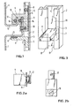
- Fig. 1 the suspension of the sheet metal shells 1 is shown in a vertical section through a horizontal joint area.
- a vertical guide rail 2 there is a support 3, the height of which is fixed, and a holding device, hereinafter referred to as holder 4, which is vertically displaceable.
- the support 3 is formed by an angle piece, the vertical leg 5 of which is arranged as a guide section in the guide rail 2.
- the horizontal leg 6 of the support lies on a shoulder 7 of the guide rail 2, the height of the support being fixed.
- the horizontal leg contains a cushion 8 protruding slightly above from an elastic material on which the sheet metal shell 1 rests.
- the bracket 4 has a horizontal section rectangular guide section 8 (Fig. 2a) which is guided in the guide rail 2, and a projecting part of the guide rail 9, which has two vertical grooves 10 and 11, which are open towards the bottom.
- An elastic round cord projects through the side walls of the grooves into the interior of the grooves.
- the lower sheet metal shell 1 has an upper edge section with a horizontal leg 13 and a vertical leg 14, while the lower edge section of the upper sheet metal shell has a horizontal leg 15 and a vertical leg 16.
- the length of the legs is such that the vertical leg 14 is at a distance behind the vertical leg 16, with their free ends being approximately at the same height.
- the horizontal leg 13 of the lower sheet metal shell 1 rests on the support 3, with only vertical forces being absorbed by the support 3.
- the holder 4 is pushed onto the vertical leg 14 in such a way that the head end of the vertical leg 14 lies against the groove base.
- the vertical leg 16 of the upper sheet metal shell engages in the holder 4 so that a game remains between its head end and the groove base.
- the horizontal leg 15 is slightly spaced from the opposite section of the holder 4.
- the vertical legs 14 and 16 engage with lateral play in the grooves 10 and 11, but they are seated in the press fit due to the elastic round cord 12.
- the bracket 4 is fixed in height in the guide rail 2 by means of a brake screw 17.
- the vertical leg 14 of the lower sheet metal shell 1 is fastened in the holder 4 by means of a screw 18.
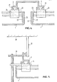
- the guide rails 2 essentially have the shape of a U-profile, the opening of which is partially closed by short webs 19 on both sides.
- a support 3 shows a support 3 in a fixed installation position in the guide rail 2.
- a window 20 is formed for inserting the support 3 by punching out the webs 19 of the guide rails 20.
- the horizontal leg 6 of the angular support 3 rests on the short webs 19, whereby the support 3 is fixed in height.
- Fig. 5 shows an embodiment in which the guide rails 2 are attached to a substructure.
- the substructure has continuous vertical U-profiles 26, which are fastened to the building wall 28 by means of brackets 27, these U-profiles 26 each being located in the region of the vertical joints of the facade.
- the guide rails 2 are each attached to the two outer sides of the U-profiles 26.
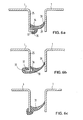
- 6a, 6b and 6c show an embodiment in which the supports or brackets are attached directly to the building wall or to the window constructions without a U-profile being provided in the area of the vertical joints.
- the vertical joints are closed by continuous sealing profiles 29, 30 and 31.
- the sheet metal shells 1 are provided on one of their angled vertical edge sections 25 with a web 32 or 33 running at right angles thereto, which either points in the direction of the joint or away from it.
- the sealing profiles 29 and 30 engage with their claws 34 and 35 or 36 and 37 with elastic deformation, the webs 32 or 33, while they rest with their other lateral edge section 38 or 39 on the opposite vertical edge section 25.
- 6c shows an embodiment in which the sealing profile 31 with its claws engages around the end region of the vertical edge section 25, with no separate web being provided here for fastening the sealing profile.
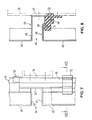
- facade elements 40 the upper edge section of which likewise has a horizontal leg 41 and an adjoining upwardly extending leg 42.
- the facade elements 40 are fastened to this upper edge section by means of supports, not shown, which essentially correspond to those according to FIG. 1.
- the lower edge section of the facade elements 40 has only one leg 43 which is angled horizontally inwards. Since the leg 43 is considerably shorter than the leg 41, a sufficiently large air inlet opening remains in the area of the horizontal joint for the rear ventilation of the facade cladding.
- a lateral edge section 44 of the facade elements 40 is angled in a U-shape with an inwardly directed leg 45, a subsequent leg 47 covering the vertical joint 46 between two adjacent facade elements 40 and a short, bent-back leg 48.
- the other the lateral edge section 49 of the facade elements 40 has an inwardly angled leg 50, which is considerably shorter than the adjacent leg 45 of the adjacent facade element 40, and a short second leg 51 bent back.
- the facade elements 40 are arranged side by side in such a way that the leg 47 closes the vertical joint 46 optically, the short legs 48 and 51 and an adjacent portion of the leg 47 being received in grooves of profile pieces 52 in a press fit, which are arranged one above the other at a distance are. Between the legs 47, 48 of the side edge section 44 and the legs 51, 50 of the other side edge section 49 and the superimposed profile pieces 52 there remains a sufficiently large, free cross section through which the air can circulate, so that the entire facade cladding is well ventilated.
- the U-shaped lateral edge section 44 protrudes by a section 53 above the upper edge of the leg 42, to be precise by an amount which corresponds to the length of the leg 41, this being from the edge of the Facade elements 40 results from a rectangular sheet metal plate.
- the U-shaped edge section 44 is widened and, as shown in FIG. 7, cranked by a material thickness, so that the section 53 can engage behind the U-shaped side edge section 44 of the facade element 40 arranged above it.
- the overlapping sections are guided into one another.
- a horizontally extending U-profile 55 of the substructure is provided, to which the facade elements 40 are screwed with screws 57 for their additional securing.
- the profile pieces 52 can each in a recess of a component 56 of the substructure of the facade can be arranged in the clamp seat.
Landscapes
- Engineering & Computer Science (AREA)
- Architecture (AREA)
- Civil Engineering (AREA)
- Structural Engineering (AREA)
- Finishing Walls (AREA)
- Building Environments (AREA)
Priority Applications (1)
| Application Number | Priority Date | Filing Date | Title |
|---|---|---|---|
| AT85115462T ATE65821T1 (de) | 1985-05-14 | 1985-12-05 | Fassadenverkleidung aus hinterluefteten schalenfoermigen fassadenelementen. |
Applications Claiming Priority (2)
| Application Number | Priority Date | Filing Date | Title |
|---|---|---|---|
| DE19853517443 DE3517443A1 (de) | 1985-05-14 | 1985-05-14 | Haltekonstruktion fuer hinterlueftete fassaden aus schalenfoermigen fassadenelementen |
| DE3517443 | 1985-05-14 |
Related Child Applications (1)
| Application Number | Title | Priority Date | Filing Date |
|---|---|---|---|
| EP91100277.2 Division-Into | 1991-01-10 |
Publications (3)
| Publication Number | Publication Date |
|---|---|
| EP0201630A2 true EP0201630A2 (fr) | 1986-11-20 |
| EP0201630A3 EP0201630A3 (en) | 1988-01-27 |
| EP0201630B1 EP0201630B1 (fr) | 1991-07-31 |
Family
ID=6270753
Family Applications (2)
| Application Number | Title | Priority Date | Filing Date |
|---|---|---|---|
| EP19910100277 Withdrawn EP0429431A3 (en) | 1985-05-14 | 1985-12-05 | Facade covering by cavity wall elements with behind ventilation |
| EP85115462A Expired - Lifetime EP0201630B1 (fr) | 1985-05-14 | 1985-12-05 | Revêtement de façade par des éléments à double parois avec ventilation arrière |
Family Applications Before (1)
| Application Number | Title | Priority Date | Filing Date |
|---|---|---|---|
| EP19910100277 Withdrawn EP0429431A3 (en) | 1985-05-14 | 1985-12-05 | Facade covering by cavity wall elements with behind ventilation |
Country Status (3)
| Country | Link |
|---|---|
| EP (2) | EP0429431A3 (fr) |
| AT (1) | ATE65821T1 (fr) |
| DE (2) | DE3517443A1 (fr) |
Cited By (8)
| Publication number | Priority date | Publication date | Assignee | Title |
|---|---|---|---|---|
| EP0283371A1 (fr) * | 1987-03-03 | 1988-09-21 | Fornells S.A. | Dispositif d'assemblage de traverses et de bardages pour constituer notamment des palissades, des cloisonnements et des parements |
| FR2617224A1 (fr) * | 1987-06-26 | 1988-12-30 | Fornells Sa | Dispositif d'assemblage de traverses et de bardages au moyen de profiles pour constituer notamment des palissades, des cloisonnements et des parements |
| FR2636654A1 (fr) * | 1988-09-16 | 1990-03-23 | Vano Productions Sa | Elements de construction de panneaux et panneaux construits avec ces elements |
| EP0567087A1 (fr) * | 1992-04-23 | 1993-10-27 | Rolf Rand | Dispositif de fixation pour revêtements de façade |
| NL1006233C2 (nl) * | 1997-06-04 | 1998-12-07 | Reynolds Aluminium Bv | Gevelbekledingssysteem en gevelbekledingspaneel. |
| EP0908575A1 (fr) * | 1997-10-10 | 1999-04-14 | Samsa Apa S.r.l. | Elément de couverture pour murs |
| US20220064962A1 (en) * | 2018-10-25 | 2022-03-03 | 3A Composites Gmbh | Cladding system for a wall, arrangement of tile cladding system and method for mounting the cladding system |
| WO2023041821A1 (fr) | 2021-09-17 | 2023-03-23 | Sistemas Tecnicos Del Accesorio Y Componentes, S.L. | Dispositif pour façade ventilée |
Families Citing this family (8)
| Publication number | Priority date | Publication date | Assignee | Title |
|---|---|---|---|---|
| DE4005508C2 (de) * | 1990-02-21 | 2001-08-16 | Gruenzweig & Hartmann Montage | Fassadenverkleidung |
| DE4140867A1 (de) * | 1991-12-11 | 1993-06-24 | Riedinger Mmm Gmbh & Co Kg | Fassadenkonstruktion |
| DE9208035U1 (de) * | 1992-06-16 | 1992-09-03 | Lang Metallbau GmbH, 6324 Feldatal | Fassadenbekleidung |
| DE19811363C2 (de) * | 1998-03-16 | 2001-11-29 | Gerhard Hermeling | Unterkonstruktion für Wand- und Deckenbekleidungen |
| FR2776748B1 (fr) * | 1998-03-24 | 2000-05-26 | Haironville Sa | Corniere de support d'un assemblage de plateaux |
| EP1914362A1 (fr) * | 2006-10-17 | 2008-04-23 | Armstrong Metalldecken AG | Revêtement de mur |
| CH700659A1 (de) * | 2009-03-25 | 2010-09-30 | Montana Bausysteme Ag | Befestigungselement für Fassadenpaneele und Fassadenbekleidungssystem. |
| DE102016101405A1 (de) | 2016-01-27 | 2017-07-27 | Wilhelm Flender Gmbh & Co. Kg | Fassadenkassette und Fassadenverkleidung mit einer solchen |
Family Cites Families (10)
| Publication number | Priority date | Publication date | Assignee | Title |
|---|---|---|---|---|
| DE1189696B (de) * | 1960-04-27 | 1965-03-25 | Voest Ag | Wandverkleidung aus wannenfoermigen Blechkoerpern |
| CH413314A (de) * | 1963-01-16 | 1966-05-15 | Neveu Rene | Verbindungs- und Befestigungsmittel für aus Platten, Bändern und dergl. Materialien hergestellte Dach- und Wandverkleidungen |
| GB1125123A (en) * | 1965-09-01 | 1968-08-28 | Jules Scott Zibell | Improved building system for attaching panels to structural supports |
| DE1659605A1 (de) * | 1967-12-14 | 1971-01-28 | Busch Jaeger Duerener Metall | Befestigungsanordnung fuer Verkleidungsbleche |
| DE1816934A1 (de) * | 1968-12-24 | 1970-07-02 | Ahlers Heizkessel Gmbh | Dichtleiste fuer die Trennfugen von Wandplatten |
| FR2094397A6 (fr) * | 1970-06-19 | 1972-02-04 | Cib Couverture Indle | |
| DE2217631A1 (de) * | 1972-04-12 | 1973-10-25 | Uhl Kg Geb | Bausatz fuer eine fassadenverkleidung |
| DE2409028A1 (de) * | 1974-02-25 | 1975-09-04 | Wendker Gmbh & Co Kg | Halteelement fuer fassadenpaneele |
| DE2927164A1 (de) * | 1979-07-05 | 1981-01-08 | Hesa Alu Bauelemente Herbert S | Fassadenverkleidung |
| DE3312150A1 (de) * | 1983-04-02 | 1984-10-11 | Eltreva Ag, Aesch | Fassadenverkleidung mit unterkonstruktion |
-
1985
- 1985-05-14 DE DE19853517443 patent/DE3517443A1/de not_active Withdrawn
- 1985-12-05 AT AT85115462T patent/ATE65821T1/de not_active IP Right Cessation
- 1985-12-05 DE DE8585115462T patent/DE3583680D1/de not_active Expired - Fee Related
- 1985-12-05 EP EP19910100277 patent/EP0429431A3/de not_active Withdrawn
- 1985-12-05 EP EP85115462A patent/EP0201630B1/fr not_active Expired - Lifetime
Cited By (11)
| Publication number | Priority date | Publication date | Assignee | Title |
|---|---|---|---|---|
| EP0283371A1 (fr) * | 1987-03-03 | 1988-09-21 | Fornells S.A. | Dispositif d'assemblage de traverses et de bardages pour constituer notamment des palissades, des cloisonnements et des parements |
| FR2617224A1 (fr) * | 1987-06-26 | 1988-12-30 | Fornells Sa | Dispositif d'assemblage de traverses et de bardages au moyen de profiles pour constituer notamment des palissades, des cloisonnements et des parements |
| FR2636654A1 (fr) * | 1988-09-16 | 1990-03-23 | Vano Productions Sa | Elements de construction de panneaux et panneaux construits avec ces elements |
| EP0567087A1 (fr) * | 1992-04-23 | 1993-10-27 | Rolf Rand | Dispositif de fixation pour revêtements de façade |
| NL1006233C2 (nl) * | 1997-06-04 | 1998-12-07 | Reynolds Aluminium Bv | Gevelbekledingssysteem en gevelbekledingspaneel. |
| EP0882853A1 (fr) | 1997-06-04 | 1998-12-09 | Reynolds Aluminium Holland B.V. | Système de revêtement pour façades et panneau de façade |
| EP0908575A1 (fr) * | 1997-10-10 | 1999-04-14 | Samsa Apa S.r.l. | Elément de couverture pour murs |
| US20220064962A1 (en) * | 2018-10-25 | 2022-03-03 | 3A Composites Gmbh | Cladding system for a wall, arrangement of tile cladding system and method for mounting the cladding system |
| US12276116B2 (en) * | 2018-10-25 | 2025-04-15 | 3A Composites Gmbh | Cladding system for a wall, arrangement of tile cladding system and method for mounting the cladding system |
| WO2023041821A1 (fr) | 2021-09-17 | 2023-03-23 | Sistemas Tecnicos Del Accesorio Y Componentes, S.L. | Dispositif pour façade ventilée |
| US12565777B2 (en) | 2021-09-17 | 2026-03-03 | Sistemas Tecnicos Del Accesorio Y Componentes, S.L. | Device for a ventilated facade |
Also Published As
| Publication number | Publication date |
|---|---|
| DE3583680D1 (de) | 1991-09-05 |
| DE3517443A1 (de) | 1986-11-20 |
| EP0201630B1 (fr) | 1991-07-31 |
| EP0429431A3 (en) | 1991-11-13 |
| EP0201630A3 (en) | 1988-01-27 |
| EP0429431A2 (fr) | 1991-05-29 |
| ATE65821T1 (de) | 1991-08-15 |
Similar Documents
| Publication | Publication Date | Title |
|---|---|---|
| DE3910158C2 (de) | Verstellbarer Türstock | |
| DE69306761T2 (de) | Mechanismus für Glasschiebetüren | |
| EP0148123B1 (fr) | Structure de caisse de voiture, notamment ferroviaire | |
| EP0201630A2 (fr) | Revêtement de façade par des éléments à double parois avec ventilation arrière | |
| EP1413031A1 (fr) | Structure | |
| DE3728873A1 (de) | Aufhaengevorrichtung fuer zimmerdecken mit einschnappbaren paneelen | |
| EP1439278B1 (fr) | Joint automatique pour portes avec support adjustable | |
| EP0298328B1 (fr) | Mur de façade | |
| DE2611323A1 (de) | Einstellvorrichtung | |
| DE102006014719B4 (de) | Trägerprofil und Befestigungsanordnung eines Sitzuntergestells an einer Bodenanlage eines Omnibusses | |
| DE2522112A1 (de) | Fensterzarge | |
| DE3245851A1 (de) | Gelaender | |
| EP0508990B1 (fr) | Parement de bord de toiture | |
| EP1275810B1 (fr) | Kit pour insérer un élément mural dans une ouverture d'une double cloison à poteaux | |
| DE19613043A1 (de) | Pfosten-Sprossen-Konstruktion | |
| DE69209472T2 (de) | Verkleidungssystem für Vorhangsfassade | |
| DE29509555U1 (de) | Schaltschrank mit Montageplatte als Einzel- oder Anreihschrank | |
| DE2329075B2 (de) | Unterdecke | |
| DE8616775U1 (de) | Fassadenverkleidung aus hinterlüfteten schalenförmigen Fassadenelementen | |
| DE2623781A1 (de) | Verfahren sowie bauteile zum ausruesten insbesondere von altbauten mit kunststoffenstern | |
| EP0409029A1 (fr) | Profilé pour le support de panneaux de plafond | |
| EP0736436B1 (fr) | Véhicule ferroviaire | |
| DE2803625A1 (de) | Balkon-verkleidung | |
| DE10250498A1 (de) | Metallschindel-Abdeckung für Dächer oder Fassaden | |
| DE102021125670A1 (de) | Absturzsicherung für eine Gebäudeöffnung und Verfahren zur Montage einer Absturzsicherung |
Legal Events
| Date | Code | Title | Description |
|---|---|---|---|
| PUAI | Public reference made under article 153(3) epc to a published international application that has entered the european phase |
Free format text: ORIGINAL CODE: 0009012 |
|
| AK | Designated contracting states |
Kind code of ref document: A2 Designated state(s): AT BE CH DE FR GB IT LI LU NL SE |
|
| ITCL | It: translation for ep claims filed |
Representative=s name: BUGNION S.P.A. |
|
| TCNL | Nl: translation of patent claims filed | ||
| EL | Fr: translation of claims filed | ||
| PUAL | Search report despatched |
Free format text: ORIGINAL CODE: 0009013 |
|
| AK | Designated contracting states |
Kind code of ref document: A3 Designated state(s): AT BE CH DE FR GB IT LI LU NL SE |
|
| 17P | Request for examination filed |
Effective date: 19880423 |
|
| 17Q | First examination report despatched |
Effective date: 19891009 |
|
| GRAA | (expected) grant |
Free format text: ORIGINAL CODE: 0009210 |
|
| RAP1 | Party data changed (applicant data changed or rights of an application transferred) |
Owner name: MBS GEMONT AG |
|
| AK | Designated contracting states |
Kind code of ref document: B1 Designated state(s): AT BE CH DE FR GB IT LI LU NL SE |
|
| REF | Corresponds to: |
Ref document number: 65821 Country of ref document: AT Date of ref document: 19910815 Kind code of ref document: T |
|
| XX | Miscellaneous (additional remarks) |
Free format text: TEILANMELDUNG 91100277.2 EINGEREICHT AM 05/12/85. |
|
| REF | Corresponds to: |
Ref document number: 3583680 Country of ref document: DE Date of ref document: 19910905 |
|
| ET | Fr: translation filed | ||
| ITF | It: translation for a ep patent filed | ||
| GBT | Gb: translation of ep patent filed (gb section 77(6)(a)/1977) | ||
| PLBE | No opposition filed within time limit |
Free format text: ORIGINAL CODE: 0009261 |
|
| STAA | Information on the status of an ep patent application or granted ep patent |
Free format text: STATUS: NO OPPOSITION FILED WITHIN TIME LIMIT |
|
| 26N | No opposition filed | ||
| EPTA | Lu: last paid annual fee | ||
| PGFP | Annual fee paid to national office [announced via postgrant information from national office to epo] |
Ref country code: SE Payment date: 19941223 Year of fee payment: 10 |
|
| PGFP | Annual fee paid to national office [announced via postgrant information from national office to epo] |
Ref country code: BE Payment date: 19950104 Year of fee payment: 10 |
|
| EAL | Se: european patent in force in sweden |
Ref document number: 85115462.5 |
|
| PG25 | Lapsed in a contracting state [announced via postgrant information from national office to epo] |
Ref country code: SE Effective date: 19951206 |
|
| PG25 | Lapsed in a contracting state [announced via postgrant information from national office to epo] |
Ref country code: BE Effective date: 19951231 |
|
| REG | Reference to a national code |
Ref country code: CH Ref legal event code: PUE Owner name: MBS GEMONT AG TRANSFER- MONTATEC FASSADENSYSTEME A |
|
| REG | Reference to a national code |
Ref country code: GB Ref legal event code: 732E |
|
| BERE | Be: lapsed |
Owner name: MBS GEMONT A.G. Effective date: 19951231 |
|
| PGFP | Annual fee paid to national office [announced via postgrant information from national office to epo] |
Ref country code: GB Payment date: 19971114 Year of fee payment: 13 |
|
| PGFP | Annual fee paid to national office [announced via postgrant information from national office to epo] |
Ref country code: FR Payment date: 19971124 Year of fee payment: 13 |
|
| PGFP | Annual fee paid to national office [announced via postgrant information from national office to epo] |
Ref country code: AT Payment date: 19971222 Year of fee payment: 13 |
|
| PGFP | Annual fee paid to national office [announced via postgrant information from national office to epo] |
Ref country code: NL Payment date: 19971231 Year of fee payment: 13 |
|
| PGFP | Annual fee paid to national office [announced via postgrant information from national office to epo] |
Ref country code: CH Payment date: 19980107 Year of fee payment: 13 |
|
| PGFP | Annual fee paid to national office [announced via postgrant information from national office to epo] |
Ref country code: LU Payment date: 19980217 Year of fee payment: 13 |
|
| PGFP | Annual fee paid to national office [announced via postgrant information from national office to epo] |
Ref country code: DE Payment date: 19980220 Year of fee payment: 13 |
|
| PG25 | Lapsed in a contracting state [announced via postgrant information from national office to epo] |
Ref country code: LU Free format text: LAPSE BECAUSE OF NON-PAYMENT OF DUE FEES Effective date: 19981205 Ref country code: GB Free format text: LAPSE BECAUSE OF NON-PAYMENT OF DUE FEES Effective date: 19981205 Ref country code: AT Free format text: LAPSE BECAUSE OF NON-PAYMENT OF DUE FEES Effective date: 19981205 |
|
| PG25 | Lapsed in a contracting state [announced via postgrant information from national office to epo] |
Ref country code: LI Free format text: LAPSE BECAUSE OF NON-PAYMENT OF DUE FEES Effective date: 19981231 Ref country code: CH Free format text: LAPSE BECAUSE OF NON-PAYMENT OF DUE FEES Effective date: 19981231 |
|
| PG25 | Lapsed in a contracting state [announced via postgrant information from national office to epo] |
Ref country code: NL Free format text: LAPSE BECAUSE OF NON-PAYMENT OF DUE FEES Effective date: 19990701 |
|
| GBPC | Gb: european patent ceased through non-payment of renewal fee |
Effective date: 19981205 |
|
| REG | Reference to a national code |
Ref country code: CH Ref legal event code: PL |
|
| PG25 | Lapsed in a contracting state [announced via postgrant information from national office to epo] |
Ref country code: FR Free format text: LAPSE BECAUSE OF NON-PAYMENT OF DUE FEES Effective date: 19990831 |
|
| NLV4 | Nl: lapsed or anulled due to non-payment of the annual fee |
Effective date: 19990701 |
|
| REG | Reference to a national code |
Ref country code: FR Ref legal event code: ST |
|
| PG25 | Lapsed in a contracting state [announced via postgrant information from national office to epo] |
Ref country code: DE Free format text: LAPSE BECAUSE OF NON-PAYMENT OF DUE FEES Effective date: 19991001 |