EP0201657B1 - Schiff mit Wasserstrahlvorrichtungen und Wasserstrahlvorrichtung für Schiffe - Google Patents
Schiff mit Wasserstrahlvorrichtungen und Wasserstrahlvorrichtung für Schiffe Download PDFInfo
- Publication number
- EP0201657B1 EP0201657B1 EP19850850164 EP85850164A EP0201657B1 EP 0201657 B1 EP0201657 B1 EP 0201657B1 EP 19850850164 EP19850850164 EP 19850850164 EP 85850164 A EP85850164 A EP 85850164A EP 0201657 B1 EP0201657 B1 EP 0201657B1
- Authority
- EP
- European Patent Office
- Prior art keywords
- water
- craft
- watercraft
- jet
- tube
- Prior art date
- Legal status (The legal status is an assumption and is not a legal conclusion. Google has not performed a legal analysis and makes no representation as to the accuracy of the status listed.)
- Expired
Links
- XLYOFNOQVPJJNP-UHFFFAOYSA-N water Substances O XLYOFNOQVPJJNP-UHFFFAOYSA-N 0.000 claims description 49
- 238000010276 construction Methods 0.000 description 1
- 238000004064 recycling Methods 0.000 description 1
- 230000000284 resting effect Effects 0.000 description 1
Images
Classifications
-
- B—PERFORMING OPERATIONS; TRANSPORTING
- B63—SHIPS OR OTHER WATERBORNE VESSELS; RELATED EQUIPMENT
- B63H—MARINE PROPULSION OR STEERING
- B63H11/00—Marine propulsion by water jets
- B63H11/02—Marine propulsion by water jets the propulsive medium being ambient water
- B63H11/10—Marine propulsion by water jets the propulsive medium being ambient water having means for deflecting jet or influencing cross-section thereof
- B63H11/107—Direction control of propulsive fluid
- B63H11/113—Pivoted outlet
Definitions
- the present invention relates to a watercraft fitted with water-jet propulsion unit, in accordance with the preamble of Claim 1, and to a water-jet propulsion unit for watercraft.
- a water-jet propulsion unit for watercraft comprises a pump, normally a propeller pump, mounted in a suitable location, normally in the after end of the craft, and connected to a water-supply conduit which extends from an intake opening normally arranged in the bottom of the craft.
- the pump outlet is located externally of the hull of the watercraft, behind the transom, and is directed so that the jet of water generated by the pump leaves the outlet in a substantially straight, rearward direction, to propel the watercraft forwards.
- a pipe or tube which is connected to the outlet opening and can be swung about a substantially vertical axis, to change the direction of the propelling water jet for the purpose of steering the craft.
- a reversing arrangement in the form of a scoop or flap or like device for example, which can be swung into the path of the water jet, either in the fixed outlet channel or in the pivotable tube arranged rearwardly of the channel for steering the watercraft, or immediately behind the outlet orifice of the tube, so as to deflect the water jet obliquely forwards, thereby to generate a reverse thrust for slowing down and/or reversing the craft.
- the reversing device is so adapted that when occupying its active position the water jet is deflected downwardly and forwardly in a substantially vertical plane, so as to be directed beneath the bottom of the craft.
- This has certain disadvantages, which are particularly manifest in the case of certain types of watercraft.
- the forwardly and obliquely downwardly directed water jet will pass close to the bottom of the craft and therewith in the near vicinity of the intake opening of the unit water-supply channel.
- this water jet will be drawn again into the water-supply channel and fed to the pump, meaning in reality that water will be recycled through the unit by the pump.
- the reversing device of each of the two water-jet units is so formed and arranged on the pivotable tube that when a respective reversing device occupies its active position the propelling water jet is directed obliquely forwards towards and solely towards the side remote from the centre line thereof, such that said deflected water jet passes substantially outwardly of that side of the craft hull adjacent the unit.
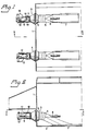
- Figs. 1 and 2 illustrate schematically the stern part of a watercraft, including a transom 1 and bottom 2.
- the illustrated craft is provided with two jet propulsion units, generally referenced 3 and 4, which are mounted in the stern symmetrically on both sides of the centre line of the craft.
- Each of the jet propulsion units includes a propeller pump having a pump housing 5 which is so mounted in the transom 1 that the inlet to the pump housing 5 is located within the hull of the vessel, while the outlet opening from the pump housing is located externally of the transom 1 and is pointed in a substantially straight and rearward direction.
- a water supply channel 6 Connected to the inlet of the pump housing 5 is a water supply channel 6 which extends from a water intake 7 in the bottom 2 of the craft.
- the pump impeller in the pump housing 5 is driven by a shaft 8 from a drive machine (not shown) mounted within the craft.
- a pipe or tube 9 Connected to the outlet opening of the pump housing 5 is a pipe or tube 9 which can be swung by means of piston- cylinder devices 10 about a substantially vertical axis 11 in a manner to direct the water jet exiting from the outlet opening of the pump housing 5 in a manner to steer the craft in different directions.
- jet propulsion units are of previously known construction. These jet propulsion units are described more clearly in, for example, Swedish Patent Specification 424 845. Many other embodiments of jet propulsion units of a similar kind are known to the art. It will be understood that the two jet propulsion units 3 and 4 mounted on the watercraft illustrated by way of example in the drawing are constructed in mutually the same manner in the aforedescribed respects.
- This reversing device may have a number of different forms, and may comprise, for example, a scoop-like member or a flap or some like device arranged for movement from an inactive position to an active position in which it is located in the path of the water jet, so as to deflect the jet to a substantially forward direction.
- the reversing device is normally mounted on the pivotable steering tube so that deflection of the jet is effected in the tube or immediately behind the rearward outlet orifice thereof, thereby enabling the tube to be used for steering the craft even when moving astern.
- a conventional, known reversing device occupies its active state the water jet is normally deflected obliquely downwardly and forwardly, i.e. in a substantially vertical plane, so that the water jet passes down beneath the bottom of the craft.
- the reversing device is so designed that when occupying its active state the water jet is deflected obliquely forwardly and towards the side remote from the centre line of the craft, so that the deflected water-jet passes substantially outwardly of the near side of the hull of the craft.
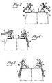
- each reversing device of respective propulsion units 3 and 4 comprises a scoop-like element 13 which can be swung into the tube 9 by means of a hydraulic piston cylinder device 12 and which is arranged on the side of the tube 9 remote from the centre line of the craft, in a manner such that with the reversing device in its active state the water jet is deflected obliquely forwardly in a substantially horizontal plane, away from the aforesaid centre line.
- the water jets 14, 15 deflected by the reversing scoops 13 and issuing from the tube propulsion units 3,4 are directed obliquely outwardly and forwardly on respective sides of the craft, as illustrated schematically in Fig. 3.
- a watercraft reversing device of this design affords the advantages discussed in the aforegoing, namely that water will not be recycled through the propulsion unit when reversing the craft, with subsequent reduction in the propelling force, and neither will the stern end of the craft be subjected to lifting forces. In addition, substantially no air will be drawn down into the water around the craft. The water jets will also pass outwardly of the hull on both sides of the craft, so as not to strike the transom thereof or to cause water to be sprayed there into to any appreciable extent.
- the reversing devices 13 When the reversing devices 13 are mounted on the pivotable tubes 9 used to steer the craft, there is afforded the additional advantages that, as illustrated in Fig. 4, the water jets 14 and 15 deflected by the reversing devices 13 and issuing from the two jet propulsion units 3 and 4 may be directed in mutually different directions by pivoting the tubes 9.
- the craft is not solely subjected to a rearwardly acting force but also to a rotary or torsional force, by means of which the craft can be swung or "twisted" free from a beach.
- the sides of the hull at the stern part of the craft may be provided with cavities or recesses 16 operative in allowing the water jets to pass in this position
Landscapes
- Chemical & Material Sciences (AREA)
- Engineering & Computer Science (AREA)
- Combustion & Propulsion (AREA)
- Mechanical Engineering (AREA)
- Ocean & Marine Engineering (AREA)
- Fire-Extinguishing By Fire Departments, And Fire-Extinguishing Equipment And Control Thereof (AREA)
- Other Liquid Machine Or Engine Such As Wave Power Use (AREA)
- Jib Cranes (AREA)
- Cleaning Or Clearing Of The Surface Of Open Water (AREA)
Claims (4)
Priority Applications (1)
| Application Number | Priority Date | Filing Date | Title |
|---|---|---|---|
| DE8585850164T DE3573909D1 (en) | 1985-05-09 | 1985-05-09 | A watercraft fitted with water-jet propulsion units, and a water-jet propulsion unit for watercraft |
Applications Claiming Priority (1)
| Application Number | Priority Date | Filing Date | Title |
|---|---|---|---|
| SE8400727A SE8400727L (sv) | 1984-02-10 | 1984-02-10 | Straldriftsaggregat for fartyg |
Publications (2)
| Publication Number | Publication Date |
|---|---|
| EP0201657A1 EP0201657A1 (de) | 1986-11-20 |
| EP0201657B1 true EP0201657B1 (de) | 1989-10-25 |
Family
ID=20354691
Family Applications (1)
| Application Number | Title | Priority Date | Filing Date |
|---|---|---|---|
| EP19850850164 Expired EP0201657B1 (de) | 1984-02-10 | 1985-05-09 | Schiff mit Wasserstrahlvorrichtungen und Wasserstrahlvorrichtung für Schiffe |
Country Status (2)
| Country | Link |
|---|---|
| EP (1) | EP0201657B1 (de) |
| SE (1) | SE8400727L (de) |
Families Citing this family (1)
| Publication number | Priority date | Publication date | Assignee | Title |
|---|---|---|---|---|
| US6875064B2 (en) * | 2003-06-13 | 2005-04-05 | Bombardier Recreational Products Inc. | Reverse gate for a watercraft |
Family Cites Families (4)
| Publication number | Priority date | Publication date | Assignee | Title |
|---|---|---|---|---|
| US3680315A (en) * | 1970-10-12 | 1972-08-01 | Twin Disc Inc | Hydraulic jet propulsion apparatus |
| US3756185A (en) * | 1972-03-08 | 1973-09-04 | Custom Speed Marine Inc | Water jet boat thrust trimmer |
| US4252075A (en) * | 1976-10-28 | 1981-02-24 | Yamaha Hatsudoki Kabushiki Kaisha | Water jet propulsion system with laterally disposed reverse ports |
| IT1177771B (it) * | 1983-06-08 | 1987-08-26 | Dowty Hydraulic Units Ltd | Perfezionamento nei complessi propulsori marini a getto |
-
1984
- 1984-02-10 SE SE8400727A patent/SE8400727L/ not_active Application Discontinuation
-
1985
- 1985-05-09 EP EP19850850164 patent/EP0201657B1/de not_active Expired
Also Published As
| Publication number | Publication date |
|---|---|
| EP0201657A1 (de) | 1986-11-20 |
| SE8400727L (sv) | 1985-08-11 |
| SE8400727D0 (sv) | 1984-02-10 |
Similar Documents
| Publication | Publication Date | Title |
|---|---|---|
| US4977845A (en) | Boat propulsion and handling system | |
| US5591057A (en) | Hull supported steering and reversing gear for large waterjets | |
| US4437841A (en) | Outboard jet drive steering mechanism | |
| EP0085035B1 (de) | Umkehreinrichtung für ein Wasserstrahl-Antriebsaggregat | |
| US4807552A (en) | Small boat bow thruster | |
| WO1988009288A1 (en) | Reversing device of a jet propulsion assembly for a ship | |
| US6071156A (en) | Surface vessel with a fully submerged waterjet propulsion system | |
| EP1050454A2 (de) | Anordnung von aussen anzubringenden, elektrisch angetriebenen Propulsionsmodulen für SWATH-Schiffe | |
| US6171159B1 (en) | Steering and backing systems for waterjet craft with underwater discharge | |
| JPS5848399B2 (ja) | キヤビテ−シヨンボウシバンオユウスル センパクヨウスイシンソウチ | |
| US20260015073A1 (en) | Integrated thruster apparatus for a marine vessel | |
| EP0765270B1 (de) | Wasserstrahlantrieb für ein wasserfahrzeug | |
| US4863404A (en) | Jet propulsion and stabilization means for ships | |
| NZ195791A (en) | Steering mechanism for marine jet propulsion unit | |
| KR100649174B1 (ko) | 워터제트 추진 시스템을 갖는 수상 선박 | |
| US6629866B2 (en) | Marine vehicle propulsion system | |
| US4004544A (en) | Twin turbine-wheel driven boat | |
| EP0201657B1 (de) | Schiff mit Wasserstrahlvorrichtungen und Wasserstrahlvorrichtung für Schiffe | |
| US3090346A (en) | Boat propelling water jet nozzle | |
| US3807346A (en) | Waterjet steering and reversing mechanism | |
| US6203388B1 (en) | Integrated external electric drive propulsion module arrangement for surface ships | |
| US5910032A (en) | Marine propulsion system | |
| CA2419669A1 (en) | Boat thruster apparatus and method | |
| US3826217A (en) | Jet propulsion apparatus for boats | |
| EP0249321A2 (de) | Schiffskörper |
Legal Events
| Date | Code | Title | Description |
|---|---|---|---|
| PUAI | Public reference made under article 153(3) epc to a published international application that has entered the european phase |
Free format text: ORIGINAL CODE: 0009012 |
|
| AK | Designated contracting states |
Kind code of ref document: A1 Designated state(s): DE FR GB IT NL SE |
|
| 17P | Request for examination filed |
Effective date: 19870205 |
|
| 17Q | First examination report despatched |
Effective date: 19871030 |
|
| GRAA | (expected) grant |
Free format text: ORIGINAL CODE: 0009210 |
|
| AK | Designated contracting states |
Kind code of ref document: B1 Designated state(s): DE FR GB IT NL SE |
|
| ITF | It: translation for a ep patent filed | ||
| ET | Fr: translation filed | ||
| REF | Corresponds to: |
Ref document number: 3573909 Country of ref document: DE Date of ref document: 19891130 |
|
| PLBE | No opposition filed within time limit |
Free format text: ORIGINAL CODE: 0009261 |
|
| STAA | Information on the status of an ep patent application or granted ep patent |
Free format text: STATUS: NO OPPOSITION FILED WITHIN TIME LIMIT |
|
| 26N | No opposition filed | ||
| ITTA | It: last paid annual fee | ||
| PGFP | Annual fee paid to national office [announced via postgrant information from national office to epo] |
Ref country code: GB Payment date: 19920429 Year of fee payment: 8 |
|
| PGFP | Annual fee paid to national office [announced via postgrant information from national office to epo] |
Ref country code: FR Payment date: 19920511 Year of fee payment: 8 |
|
| PGFP | Annual fee paid to national office [announced via postgrant information from national office to epo] |
Ref country code: SE Payment date: 19920521 Year of fee payment: 8 |
|
| PGFP | Annual fee paid to national office [announced via postgrant information from national office to epo] |
Ref country code: DE Payment date: 19920529 Year of fee payment: 8 |
|
| PGFP | Annual fee paid to national office [announced via postgrant information from national office to epo] |
Ref country code: NL Payment date: 19920531 Year of fee payment: 8 |
|
| PG25 | Lapsed in a contracting state [announced via postgrant information from national office to epo] |
Ref country code: GB Effective date: 19930509 |
|
| PG25 | Lapsed in a contracting state [announced via postgrant information from national office to epo] |
Ref country code: SE Effective date: 19930510 |
|
| PG25 | Lapsed in a contracting state [announced via postgrant information from national office to epo] |
Ref country code: NL Effective date: 19931201 |
|
| GBPC | Gb: european patent ceased through non-payment of renewal fee |
Effective date: 19930509 |
|
| NLV4 | Nl: lapsed or anulled due to non-payment of the annual fee | ||
| PG25 | Lapsed in a contracting state [announced via postgrant information from national office to epo] |
Ref country code: FR Effective date: 19940131 |
|
| PG25 | Lapsed in a contracting state [announced via postgrant information from national office to epo] |
Ref country code: DE Effective date: 19940201 |
|
| REG | Reference to a national code |
Ref country code: FR Ref legal event code: ST |
|
| EUG | Se: european patent has lapsed |
Ref document number: 85850164.6 Effective date: 19931210 |