EP0201660B1 - Dresseuse à rouleaux pour pièces allongées - Google Patents
Dresseuse à rouleaux pour pièces allongées Download PDFInfo
- Publication number
- EP0201660B1 EP0201660B1 EP86100446A EP86100446A EP0201660B1 EP 0201660 B1 EP0201660 B1 EP 0201660B1 EP 86100446 A EP86100446 A EP 86100446A EP 86100446 A EP86100446 A EP 86100446A EP 0201660 B1 EP0201660 B1 EP 0201660B1
- Authority
- EP
- European Patent Office
- Prior art keywords
- roller
- straightening
- machine
- hinge
- spring
- Prior art date
- Legal status (The legal status is an assumption and is not a legal conclusion. Google has not performed a legal analysis and makes no representation as to the accuracy of the status listed.)
- Expired
Links
Images


Classifications
-
- B—PERFORMING OPERATIONS; TRANSPORTING
- B21—MECHANICAL METAL-WORKING WITHOUT ESSENTIALLY REMOVING MATERIAL; PUNCHING METAL
- B21D—WORKING OR PROCESSING OF SHEET METAL OR METAL TUBES, RODS OR PROFILES WITHOUT ESSENTIALLY REMOVING MATERIAL; PUNCHING METAL
- B21D3/00—Straightening or restoring form of metal rods, metal tubes, metal profiles, or specific articles made therefrom, whether or not in combination with sheet metal parts
- B21D3/02—Straightening or restoring form of metal rods, metal tubes, metal profiles, or specific articles made therefrom, whether or not in combination with sheet metal parts by rollers
- B21D3/04—Straightening or restoring form of metal rods, metal tubes, metal profiles, or specific articles made therefrom, whether or not in combination with sheet metal parts by rollers arranged on axes skew to the path of the work
Definitions
- the invention relates to a roller straightening machine for elongated workpieces acc. the preamble of claim 1.
- a roller straightening machine of this type is known from US-A-3 533 257.
- the straightening rolls are regularly rotatably mounted in roll holders around their longitudinal axis and, in the case of inclined roll straightening machines, can also be swiveled around an axis in the transverse plane of the straightened material.
- At least one roll holder is adjustable transversely to the longitudinal extent of the direction, i.e. movably guided in the machine frame in order to be able to adjust the leveling machine to the dimensions of the leveling material.
- roller straightening machines it is known to secure at least one roller against overload.
- the roll in question shifts in the event of an overload in a direction transverse to the longitudinal extent of the material to be straightened.
- Such a straightening machine is known from DE-PS-1 910 879.
- the lower roller of a 2-roller straightening machine shown there is mounted on a slide that is pressed hydraulically against the workpiece.
- the problem with overload protection is that the rigidity of the straightening machine must not be affected by the overload protection.
- an oblique roller straightening machine is known with three pairs of lines arranged in line and opposite one another on the straightening rolls, with which essentially pipes are to be straightened.
- the straightening rollers are mounted in roller holders that can be swiveled around axes in the straightening plane.
- the swivel axes are arranged at right angles to the path of the target.
- Each roller of a pair of rollers is hydraulically cushioned to prevent damage to the machine or workpiece in the event of an overload due to a "thick" workpiece.
- the reel seat is hydraulically biased against a stop.
- the invention has for its object to simplify the overload protection for rollers of roller straightening machines.
- the roller holder is designed as a rocker which, when an overload occurs, recedes on the side facing away from the joint against the force of the spring and thereby releases the path of the material to be straightened. It is essential to recognize that the overload of the straightening machine is regularly due to the slight oversize of the straightening good. Straightening material that is much too “thick” can be easily recognized and does not fit between the intended insertion funnels or guidelines on 2-roll straightening machines and therefore does not even get between the straightening rolls themselves. Overloading by workpieces that are too “thick” can result therefore be excluded. In the present invention, a way out for oversize workpieces is found which, for. B. make up only 1 mm.
- the embodiment of the invention according to claim 3 allows the entire roll holder to be clamped firmly to the machine frame without additional structural effort by the tie rod and the spring.
- the embodiment of the invention according to claim 4 ensures that the evasive movement of the roller takes place approximately in the transverse direction to the straightening good.
- the arrangement of the joint and spring between the roll holder and the machine frame is preferably provided.
- the force required for the spring is approximately halved by designing the roller holder as a rocker.
- the feature of claim 5 offers the possibility of connecting the spring to an existing hydraulic station.
- the feature of claim 6 serves a wide support of the roll holder on the machine frame and a further reduction in the pressure required for the individual hydraulic spring.
- Claim 8 serves to simplify the construction of the joint.
- the joint is arranged in the area of the longitudinal end of the straightening roller secured against overload. He is assigned one foot each on the straightening roller carrier, which lifts it from the machine frame, so that there is a gap between the straightening roller carrier and the machine frame, which opens up the possibility that the straightening roller carrier will be overloaded at the opposite, outlet-side longitudinal end on which the spring is arranged , can lower.
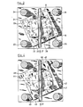
- FIG. 1 shows a 2-roller straightening machine 1, in which the machine frame 6 consists of an upper crosshead 21, a lower crossmember 22 and four columns 23 to 26 arranged in the four corners of the crosshead and crossbar.
- the straightening rollers 2, 3 have intersecting axes in a plan view.
- the columns 23 to 26 connect the upper crosshead 21 to the lower crossmember 22.
- a roller holder 4 is arranged on the lower crosshead 21. It is pivotable and displaceable in the vertical direction in the crosshead 21.
- a roller holder 5 is clamped on the lower crossmember 22 between the columns 23 to 26. It consists of a base plate 17 and a fork piece 18 in which the straightening roller 3 is rotatably mounted. As indicated in FIG. 2, 28 rulers 30, 36 are provided laterally next to the workpiece, which prevent the workpiece from laterally deflecting between the straightening rollers 2, 3.
- the workpiece 28 moves on a helical path between the straightening rollers 2, 3 and the straightening rulers 30, 36 in the direction of the arrows 29 and 37 through the straightening machine 1.
- the swivel adjustment of the two roller holders 4, 5 is used to adjust the deflection of the workpiece 28.
- the fork piece 18 of the lower roller holder 5 can be adjusted relative to the base plate 17 against the base plate 17 carrying it by means of the swivel adjusting device 27.
- the lower roller holder 5 of the 2-roll straightening machine 1 can be pivoted by a few angular degrees in order to prevent the straightening machine from being overloaded against the machine frame 6. During this pivoting movement, the distance between the straightening rollers 2, 3 increases.
- the straightening machine makes the slightly "thick" workpiece 28 between the straightening rollers somewhat more space and thus avoids overloading the machine.
- the roller holder 5 has on the longitudinal side 13 of the roller 3 facing the incoming workpiece a joint 7, which consists of two feet 32, 33 on the roller carrier 5 and each on a machine frame arranged ball stud 19, each in a cylindrical bore 20, 31 on the roller holder 5 intervenes.
- the 2 ball journals position the roller carrier on the lower crossmember 22.
- Two hydraulic springs 8, 16 are arranged on the longitudinal side 12 of the straightening roller 3 facing the outgoing workpiece in the region of the longitudinal ends 40, 41.
- a stop 9 which is designed as a tie rod and which prevents the lower roller holder 5 from being lifted off the base plate under the force of the springs 8, 16.
- the tie rod 38 shown as a screw is rigidly connected to the lower cross member 22 and serves the roller holder 5 as a stop 9.
- the springs 8, 16 press the roller holder 5 in the working direction of the roller 3 against the stop 9.
- the stop is approximately in the middle between the spring 8 and the joint 7 arranged.
- the lower roller holder 5 is clamped to the crossmember 22 by the springs 8, 16, the feet 32, 33 and the stop 9.
- the spring is a hydraulic cylinder 39 which is connected to a pump 15 and to a pressure relief valve 14.
- the pressure relief valve allows easy adjustment of the pressure to the maximum straightening force required.
- the piston of the cylinder 39 withdraws.
- the roll holder 5 with the roll 3 lowers substantially on the outlet side of the workpiece and thus widens the straightening gap to the extent necessary to avoid the overload.
- the arrangement of the joint 7 on the inlet side of the straightening machine and of the springs 8, 16 on the outlet side of the same results in an advantageous evasive movement of the straightening roller 3, which both follows the feed direction of the workpiece 28 and also widens the straightening gap at the same time.
- a support of the base plate 10 on 4 leaf springs 42, 43, 44, 45 is shown. These springs press the base plate against three stops 46, 47, 48 and thus secure their position in the desired position in the direction of the straightening force.
- two ball pins 49, 50 are provided, which project from the lower cross member of the machine frame 6 and which secure the position of the base plate 10 in the transverse direction to the straightening force.
- the base plate 17 is pivoted relative to the path 37 of the workpiece in accordance with the average operating angle of the straightening rollers 2, 3 in the machine frame 6. This ensures a defined lowering of the lower straightening roll 3 in the embodiment according to FIGS. 1 and 2. In any case, however, between the base plates 10 and 17 on the one hand and the Machine frame 6, on the other hand, an intermediate space 11 is provided, which enables the secured straightening roller to evade against the machine frame.
Landscapes
- Engineering & Computer Science (AREA)
- Mechanical Engineering (AREA)
- Straightening Metal Sheet-Like Bodies (AREA)
- Processing And Handling Of Plastics And Other Materials For Molding In General (AREA)
- Rolls And Other Rotary Bodies (AREA)
- Wire Processing (AREA)
Claims (9)
Priority Applications (1)
| Application Number | Priority Date | Filing Date | Title |
|---|---|---|---|
| AT86100446T ATE43521T1 (de) | 1985-05-13 | 1986-01-15 | Rollenrichtmaschine fuer langgestreckte werkstuecke. |
Applications Claiming Priority (2)
| Application Number | Priority Date | Filing Date | Title |
|---|---|---|---|
| DE19853517196 DE3517196A1 (de) | 1985-05-13 | 1985-05-13 | Rollenrichtmaschine fuer langgestreckte werkstuecke |
| DE3517196 | 1985-05-13 |
Publications (3)
| Publication Number | Publication Date |
|---|---|
| EP0201660A2 EP0201660A2 (fr) | 1986-11-20 |
| EP0201660A3 EP0201660A3 (en) | 1987-09-09 |
| EP0201660B1 true EP0201660B1 (fr) | 1989-05-31 |
Family
ID=6270612
Family Applications (1)
| Application Number | Title | Priority Date | Filing Date |
|---|---|---|---|
| EP86100446A Expired EP0201660B1 (fr) | 1985-05-13 | 1986-01-15 | Dresseuse à rouleaux pour pièces allongées |
Country Status (3)
| Country | Link |
|---|---|
| EP (1) | EP0201660B1 (fr) |
| AT (1) | ATE43521T1 (fr) |
| DE (2) | DE3517196A1 (fr) |
Families Citing this family (1)
| Publication number | Priority date | Publication date | Assignee | Title |
|---|---|---|---|---|
| CN110369996A (zh) * | 2019-08-09 | 2019-10-25 | 齐志刚 | 一种计算机中内存条的粗制设备 |
Family Cites Families (4)
| Publication number | Priority date | Publication date | Assignee | Title |
|---|---|---|---|---|
| GB1202067A (en) * | 1966-09-22 | 1970-08-12 | Sandvikens Jernverks Ab | Breaker bolt |
| GB1231383A (fr) * | 1967-06-09 | 1971-05-12 | ||
| DE1910879C3 (de) * | 1969-03-04 | 1978-12-07 | Th. Kieserling & Albrecht, 5650 Solingen | Richtmaschine für langgestreckte Werkstücke runden Querschnitts |
| DE2335559A1 (de) * | 1973-07-12 | 1975-01-30 | Hans Lindemann | Zweiwalzen-richtmaschine fuer stangenfoermiges gut |
-
1985
- 1985-05-13 DE DE19853517196 patent/DE3517196A1/de not_active Withdrawn
-
1986
- 1986-01-15 DE DE8686100446T patent/DE3663628D1/de not_active Expired
- 1986-01-15 AT AT86100446T patent/ATE43521T1/de not_active IP Right Cessation
- 1986-01-15 EP EP86100446A patent/EP0201660B1/fr not_active Expired
Also Published As
| Publication number | Publication date |
|---|---|
| EP0201660A3 (en) | 1987-09-09 |
| ATE43521T1 (de) | 1989-06-15 |
| EP0201660A2 (fr) | 1986-11-20 |
| DE3517196A1 (de) | 1986-11-13 |
| DE3663628D1 (en) | 1989-07-06 |
Similar Documents
| Publication | Publication Date | Title |
|---|---|---|
| DE3534428C2 (fr) | ||
| DE2002015C3 (de) | Vorrichtung zum Längsschweißen von rohrförmigen Werkstücken | |
| EP0201660B1 (fr) | Dresseuse à rouleaux pour pièces allongées | |
| DE3916594A1 (de) | Tisch mit einstellbarer woelbung fuer abkantpressen, richtplatten und aehnliche vorrichtungen | |
| DE2835514B1 (de) | Vorrichtung zum axialen Verschieben von konischen Zwischenwalzen in einem Mehrrollen-Walzgeruest | |
| EP0619155B1 (fr) | Appareil pour le dressage de produits en fil, plusieurs fil ou tubulaires | |
| CH625731A5 (fr) | ||
| CH636029A5 (de) | Hubtischfuehrung einer stranggiessanlage. | |
| EP0118812A2 (fr) | Cage de laminoir à plusieurs cylindres | |
| DE3709018C2 (de) | Vorrichtung zum Biegebearbeiten von Blechtafeln | |
| DE2224875B2 (de) | Vorrichtung zum Belasten und Trennen der Walzen eines der Bearbeitung von Bahnen, insbesondere von Papierbahnen, dienenden Walzensatzes | |
| DE4406454C1 (de) | Walzgerüst mit lose gelagerten Arbeitswalzen | |
| DE19705457A1 (de) | Blechrichtmaschine | |
| EP0022136B1 (fr) | Machine à redresser à cylindres obliques | |
| DE1452238B2 (de) | Vorrichtung zum fortlaufenden Verschweißen erhitzter Blechkanten | |
| EP0113389A1 (fr) | Dispositif pour soulager la glissière de guidage pour organes mobiles principalement dans la direction verticale, en particulier organes de machines d'usinage | |
| CH667238A5 (de) | Klebebindemaschine. | |
| EP0144304A1 (fr) | Dispositif pour le cintrage des tôles | |
| DE19857669C2 (de) | Mechanische Anordnung zur Begrenzung der Bewegung von Arbeitsbühnen | |
| DE726780C (de) | Federnder Werkzeughalter | |
| EP1434658B1 (fr) | Dispositif d'entrainement de matiere a laminer sur des cages de laminoir verticales | |
| DE2712441C2 (de) | Leimauftragsmaschine | |
| DE3406313A1 (de) | Walzgeruest | |
| DE3325493C2 (de) | Vierzehnwalzen-Walzwerk | |
| DE529795C (de) | Stempelwechselschieber fuer Doppeldruckpressen zur Herstellung von Kopfbolzen, Nieten u. dgl. |
Legal Events
| Date | Code | Title | Description |
|---|---|---|---|
| PUAI | Public reference made under article 153(3) epc to a published international application that has entered the european phase |
Free format text: ORIGINAL CODE: 0009012 |
|
| 17P | Request for examination filed |
Effective date: 19860115 |
|
| AK | Designated contracting states |
Kind code of ref document: A2 Designated state(s): AT BE CH DE FR GB IT LI SE |
|
| RTI1 | Title (correction) | ||
| PUAL | Search report despatched |
Free format text: ORIGINAL CODE: 0009013 |
|
| AK | Designated contracting states |
Kind code of ref document: A3 Designated state(s): AT BE CH DE FR GB IT LI SE |
|
| 17Q | First examination report despatched |
Effective date: 19871231 |
|
| GRAA | (expected) grant |
Free format text: ORIGINAL CODE: 0009210 |
|
| AK | Designated contracting states |
Kind code of ref document: B1 Designated state(s): AT BE CH DE FR GB IT LI SE |
|
| PG25 | Lapsed in a contracting state [announced via postgrant information from national office to epo] |
Ref country code: SE Effective date: 19890531 Ref country code: BE Effective date: 19890531 |
|
| REF | Corresponds to: |
Ref document number: 43521 Country of ref document: AT Date of ref document: 19890615 Kind code of ref document: T |
|
| REF | Corresponds to: |
Ref document number: 3663628 Country of ref document: DE Date of ref document: 19890706 |
|
| ITF | It: translation for a ep patent filed | ||
| GBT | Gb: translation of ep patent filed (gb section 77(6)(a)/1977) | ||
| ET | Fr: translation filed | ||
| PLBE | No opposition filed within time limit |
Free format text: ORIGINAL CODE: 0009261 |
|
| STAA | Information on the status of an ep patent application or granted ep patent |
Free format text: STATUS: NO OPPOSITION FILED WITHIN TIME LIMIT |
|
| 26N | No opposition filed | ||
| PGFP | Annual fee paid to national office [announced via postgrant information from national office to epo] |
Ref country code: AT Payment date: 19901231 Year of fee payment: 6 |
|
| ITTA | It: last paid annual fee | ||
| PGFP | Annual fee paid to national office [announced via postgrant information from national office to epo] |
Ref country code: CH Payment date: 19910220 Year of fee payment: 6 |
|
| PG25 | Lapsed in a contracting state [announced via postgrant information from national office to epo] |
Ref country code: AT Effective date: 19920115 |
|
| PG25 | Lapsed in a contracting state [announced via postgrant information from national office to epo] |
Ref country code: LI Effective date: 19920131 Ref country code: CH Effective date: 19920131 |
|
| REG | Reference to a national code |
Ref country code: CH Ref legal event code: PL |
|
| PGFP | Annual fee paid to national office [announced via postgrant information from national office to epo] |
Ref country code: GB Payment date: 19941229 Year of fee payment: 10 |
|
| PGFP | Annual fee paid to national office [announced via postgrant information from national office to epo] |
Ref country code: FR Payment date: 19950103 Year of fee payment: 10 |
|
| PGFP | Annual fee paid to national office [announced via postgrant information from national office to epo] |
Ref country code: DE Payment date: 19950220 Year of fee payment: 10 |
|
| PG25 | Lapsed in a contracting state [announced via postgrant information from national office to epo] |
Ref country code: GB Effective date: 19960115 |
|
| GBPC | Gb: european patent ceased through non-payment of renewal fee |
Effective date: 19960115 |
|
| PG25 | Lapsed in a contracting state [announced via postgrant information from national office to epo] |
Ref country code: FR Effective date: 19960930 |
|
| PG25 | Lapsed in a contracting state [announced via postgrant information from national office to epo] |
Ref country code: DE Effective date: 19961001 |
|
| REG | Reference to a national code |
Ref country code: FR Ref legal event code: ST |
|
| PG25 | Lapsed in a contracting state [announced via postgrant information from national office to epo] |
Ref country code: IT Free format text: LAPSE BECAUSE OF NON-PAYMENT OF DUE FEES;WARNING: LAPSES OF ITALIAN PATENTS WITH EFFECTIVE DATE BEFORE 2007 MAY HAVE OCCURRED AT ANY TIME BEFORE 2007. THE CORRECT EFFECTIVE DATE MAY BE DIFFERENT FROM THE ONE RECORDED. Effective date: 20050115 |