EP0201699A2 - Locking device to avoid the incorrect insertion of a video cassette - Google Patents
Locking device to avoid the incorrect insertion of a video cassette Download PDFInfo
- Publication number
- EP0201699A2 EP0201699A2 EP86104133A EP86104133A EP0201699A2 EP 0201699 A2 EP0201699 A2 EP 0201699A2 EP 86104133 A EP86104133 A EP 86104133A EP 86104133 A EP86104133 A EP 86104133A EP 0201699 A2 EP0201699 A2 EP 0201699A2
- Authority
- EP
- European Patent Office
- Prior art keywords
- cassette
- video
- locking device
- frame
- locking
- Prior art date
- Legal status (The legal status is an assumption and is not a legal conclusion. Google has not performed a legal analysis and makes no representation as to the accuracy of the status listed.)
- Withdrawn
Links
- 238000003780 insertion Methods 0.000 title claims abstract description 8
- 230000037431 insertion Effects 0.000 title claims abstract description 8
- 230000007257 malfunction Effects 0.000 description 1
- 238000000034 method Methods 0.000 description 1
Images
Classifications
-
- G—PHYSICS
- G11—INFORMATION STORAGE
- G11B—INFORMATION STORAGE BASED ON RELATIVE MOVEMENT BETWEEN RECORD CARRIER AND TRANSDUCER
- G11B15/00—Driving, starting or stopping record carriers of filamentary or web form; Driving both such record carriers and heads; Guiding such record carriers or containers therefor; Control thereof; Control of operating function
- G11B15/675—Guiding containers, e.g. loading, ejecting cassettes
- G11B15/67544—Guiding containers, e.g. loading, ejecting cassettes with movement of the cassette parallel to its main side and subsequent movement perpendicular thereto, i.e. front loading
- G11B15/67547—Guiding containers, e.g. loading, ejecting cassettes with movement of the cassette parallel to its main side and subsequent movement perpendicular thereto, i.e. front loading the two movements being made by the cassette holder
-
- G—PHYSICS
- G11—INFORMATION STORAGE
- G11B—INFORMATION STORAGE BASED ON RELATIVE MOVEMENT BETWEEN RECORD CARRIER AND TRANSDUCER
- G11B15/00—Driving, starting or stopping record carriers of filamentary or web form; Driving both such record carriers and heads; Guiding such record carriers or containers therefor; Control thereof; Control of operating function
- G11B15/02—Control of operating function, e.g. switching from recording to reproducing
- G11B15/16—Control of operating function, e.g. switching from recording to reproducing by sensing presence, absence or position of record carrier or container
- G11B15/17—Control of operating function, e.g. switching from recording to reproducing by sensing presence, absence or position of record carrier or container of container
Definitions
- the object of the invention is therefore to eliminate this disadvantage and to provide a device for avoiding the incorrect insertion of a video cassette in a video magnetic tape recorder which already prevents the cassette from passing the cassette opening of the device in the wrong position.
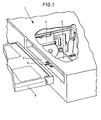
- FIG. 1 shows a partial view of a video magnetic tape device 1 which has a slot opening 2 into which a video cassette 3 can be inserted. After a cassette has been inserted into the device, it is automatically grasped by a carriage 4 and drawn into the interior of the device and lowered onto a drive level in a cassette shaft 5. To reduce malfunctions, avoid inserting the cassette incorrectly into the device. For this purpose, a locking device 6 is provided in the slot opening 2 of the device 1.
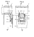
- the locking device 6 essentially consists of a pivoting part which has a U-shaped frame 7 which is pivotably mounted in a carrier 8 by means of two bearing points 9 and 9 '.
- the frame 7 has a locking lug 10 on one of the two legs.
- the locking lug prevents a cassette from being inserted incorrectly into a device, since it projects into the cassette slot opening of the video device and the frame 7 extends when it is exercised a back pressure on the locking lug does not swing out of the opening 2.
- a certain notch 11 on the cassette 3 hits the locking lug 10, and the cassette can be at least partially inserted into the interior of the device.
- the cassette slides on a sliding part 12 assigned to the locking device and the locking device is pivoted into the interior of the device against the force of a leg spring 13.
- the sliding part is designed as a roller and is mounted in the U-shaped frame 7 by means of an axis.
- the corresponding geometrical assignment of the roller and the locking lug and the frame to the bearing point of the frame in the carrier 8 ensures that the locking lug can only be pivoted away onto the roller by the cassette running up. This ensures that the locking device prevents the incorrect insertion of a cassette, regardless of the type and design of the cassette.
- the locking device is attached to the inner wall 14 of the cassette shaft 5.
Landscapes
- Automatic Tape Cassette Changers (AREA)
- Replacement Of Web Rolls (AREA)
Abstract
Beschrieben wird eine Vorrichtung zur Vermeidung des Falscheinlegens einer Videokassette in einem Video-Magnetbandgerät, wobei die Kassette über eine Schlitzöffnung in das Geräte-Innere einführbar ist, und die Geräteöffnung ein Schwenkteil aufweist das sicherstellt, daß die Kassette nur in einer bestimmten Lage die Geräteöffnung passieren kann.
Description
Es ist bekannt, daß Videokassetten für bestimmte Video-Heimgerätesysteme nur in einer vorgegebenen Lage in das Geräte-Innere eingeführt werden sollen. Wird die Kassette in eine Schlitzöffnung eines Gerätes eingeschoben, so kann erst im Inneren des Gerätes festgestellt werden, ob sich die Kassette in der für das Gerät richtigen Lage befindet. Ist sie falsch eingelegt, so muß sie aus dem Gerät herausgenommen und z. B. gewendet werden, um sie dann erneut wieder in die Kassettenöffnung einzuführen. Zur Erkennung, ob eine Kassette in der richtigen Lage in ein Gerät eingeführt ist, sind im Inneren des Gerätes Vorkehrungen getroffen, die ein entsprechendes Abtasten der Kassette ermöglichen, um festzustellen, ob eine Kassette in der erforderlichen Lage in das Gerät eingeschoben wurde und die Arbeits- und Band-Abtastelemente in Funktionslage gebracht werden können. Ein derartiger Vorgang zur richtigen Lagenermittlung einer Kassette im Gerät ist aufwendig und erfordert bei Fehllage den erneuten Zugriff zur Kassette.It is known that video cassettes for certain video home device systems should only be inserted into the device interior in a predetermined position. If the cassette is inserted into a slot opening of a device, it can only be determined inside the device whether the cassette is in the correct position for the device. If it is inserted incorrectly, it must be removed from the device and z. B. can be turned to then reinsert them into the cassette opening. In order to recognize whether a cassette is inserted into a device in the correct position, precautions have been taken inside the device, which require appropriate scanning enable the cassette to determine whether a cassette has been inserted into the device in the required position and whether the working and tape scanning elements can be brought into functional position. Such a procedure for correctly determining the position of a cassette in the device is complex and, in the event of an incorrect position, requires renewed access to the cassette.
Aufgabe der Erfindung ist es daher, diesen Nachteil zu beseitigen und eine Vorrichtung zur Vermeidung des Falscheinlegens einer Videokassette in einem Video-Magnetbandgerät zu schaffen, die es bereits verhindert, daß die Kassette in einer falschen Lage die Kassettenöffnung des Gerätes passiert.The object of the invention is therefore to eliminate this disadvantage and to provide a device for avoiding the incorrect insertion of a video cassette in a video magnetic tape recorder which already prevents the cassette from passing the cassette opening of the device in the wrong position.
Diese Aufgabe wird erfindungsgemäß durch die im Kennzeichen des Patentanspruchs 1 angegebenen Merkmale gelöst.This object is achieved by the features specified in the characterizing part of
Die Erfindung wird nachfolgend anhand der Zeichnungen näher erläutert.
- Fig. 1 ist eine perspektivische Teildarstellung eines Videogerätes mit einer Schlitzöffnung zum Einführen einer Kassette und einer Vorrichtung zur Vermeidung des Falscheinlegens der Kassette,
- Fig. 2 ist eine Draufsicht auf eine vergrößerte Darstellung der Vorrichtung zur Vermeidung des Falscheinlegens der Kassette in einem Videogerät im Schnitt B-B der Fig.2 und
- Fig. 3 ist eine Seitenansicht der
Figur 2 im Schnitt A-A.
- 1 is a partial perspective view of a video device with a slot opening for inserting a cassette and a device for preventing the cassette from being inserted incorrectly,
- Fig. 2 is a plan view of an enlarged view of the device for preventing incorrect insertion of the cassette in a video device in section BB of Fig. 2 and
- Fig. 3 is a side view of Figure 2 in section AA.
Die Figur 1 zeigt eine Teilansicht eines Video-Magnetbandgerätes 1, das eine Schlitzöffnung 2 aufweist, in die eine Video-Kassette 3 einzuschieben ist. Nach Einschieben einer Kassette in das Gerät wird diese automatisch von einem Schlitten 4 erfaßt und in das Innere des Gerätes hineingezogen und auf eine Antriebsebene in einen Kassettenschacht 5 abgesenkt. Zur Verminderung von Funktionsstörungen ist das Falscheinlegen der Kassette in das Gerät zu vermeiden. Hierzu ist eine Sperrvorrichtung 6 in der Schlitzöffnung 2 des Gerätes 1 vorgesehen.FIG. 1 shows a partial view of a video
Wie aus Figur 2 und 3 näher zu erkennen ist, besteht die Sperrvorrichtung 6 im wesentlichen aus einem Schwenkteil, das einen U-förmigen Rahmen 7 aufweist, der in einem Träger 8 mittels zweier Lagerstellen 9 und 9' schwenkbar gelagert ist. Der Rahmen 7 weist an einem der beiden Schenkel eine Sperrnase 10 auf. Die Sperrnase verhindert das Falscheinlegen einer Kassette in ein Gerät, da sie in die Kassettenschlitzöffnung des Videogerätes hineinragt und der Rahmen 7 sich beim Ausüben eines Gegendrucks auf die Sperrnase nicht aus der Öffnung 2 wegschwenken läßt. Wird jedoch die Kassette in der für das Gerät funktionsrichtigen Lage in die Schlitzöffnung eingeschoben, so trifft eine bestimmte Ausklinkung 11 an der Kassette 3 auf die Sperrnase 10, und die Kassette kann wenigstens teilweise in das Geräte-Innere eingeschoben werden. Während des teilweisen Einschiebens der Kassette in das Gerät, gleitet die Kassette auf einem der Sperrvorrichtung zugeordneten Gleitteil 12 auf und die Sperrvorrichtung wird in das Geräte-Innere entgegen der Kraft einer Schenkelfeder 13 abgeschwenkt. Das Gleitteil ist als Rolle ausgeführt und mittels einer Achse im U-förmigen Rahmen 7 gelagert. Durch die entsprechende geometrische Zuordnung der Rolle sowie der Sperrnase und des Rahmens zu der Lagerstelle des Rahmens im Träger 8, ist gewährleistet, daß die Sperrnase nur über das Auflaufen der Kassette auf die Rolle weggeschwenkt werden kann. Hiermit ist sichergestellt, daß durch die Sperrvorrichtung das Falscheinlegen einer Kassette verhindert wird, unabhängig von welcher Art und Ausführung die Kassette ist. Die Sperrvorrichtung ist an der Innenwand 14 des Kassettenschachtes 5 befestigt.As can be seen in more detail from FIGS. 2 and 3, the
Claims (3)
Applications Claiming Priority (2)
| Application Number | Priority Date | Filing Date | Title |
|---|---|---|---|
| DE19853517124 DE3517124A1 (en) | 1985-05-11 | 1985-05-11 | LOCKING DEVICE FOR AVOIDING A VIDEO CASSETTE |
| DE3517124 | 1985-05-11 |
Publications (2)
| Publication Number | Publication Date |
|---|---|
| EP0201699A2 true EP0201699A2 (en) | 1986-11-20 |
| EP0201699A3 EP0201699A3 (en) | 1988-03-23 |
Family
ID=6270562
Family Applications (1)
| Application Number | Title | Priority Date | Filing Date |
|---|---|---|---|
| EP86104133A Withdrawn EP0201699A3 (en) | 1985-05-11 | 1986-03-25 | Locking device to avoid the incorrect insertion of a video cassette |
Country Status (2)
| Country | Link |
|---|---|
| EP (1) | EP0201699A3 (en) |
| DE (1) | DE3517124A1 (en) |
Cited By (6)
| Publication number | Priority date | Publication date | Assignee | Title |
|---|---|---|---|---|
| DE3910744A1 (en) * | 1988-06-23 | 1990-01-04 | Pioneer Electronic Corp | THREADING DEVICE FOR TAPE RECORDING DEVICES |
| EP0367454A3 (en) * | 1988-10-31 | 1991-02-27 | Matsushita Electric Industrial Co., Ltd. | Cassette holder device for tape recorder |
| EP0487513A3 (en) * | 1987-11-05 | 1992-08-26 | Ampex Corporation | Cassette holding apparatus including means for preventing mis-insertion |
| EP0622796A3 (en) * | 1993-04-29 | 1995-02-15 | Tandberg Data | Conductive divider for a tape cartridge magazine with insertion error-preventing element. |
| WO1999065030A1 (en) * | 1998-06-11 | 1999-12-16 | Imation Corp. | Data storage tape cartridge with misinsertion notch |
| EP0994479A3 (en) * | 1998-10-16 | 2001-04-18 | Hewlett-Packard Company | Tape cartridge lockout system |
Family Cites Families (8)
| Publication number | Priority date | Publication date | Assignee | Title |
|---|---|---|---|---|
| FR2107551A5 (en) * | 1970-09-11 | 1972-05-05 | Sony Corp | |
| JPS522410A (en) * | 1975-11-07 | 1977-01-10 | Clarion Co Ltd | Inverse insertion prevention means for cassette deck |
| JPS53123910A (en) * | 1977-04-04 | 1978-10-28 | Funai Electric Co | Device for preventing wrong insertion of cassette |
| JPS53123909A (en) * | 1977-04-04 | 1978-10-28 | Funai Electric Co | Device for preventing wrong insertion of cassette |
| US4261527A (en) * | 1978-12-18 | 1981-04-14 | Ford Aerospace & Communications Corporation | Apparatus for preventing damage to a tape player head |
| JPS55157154A (en) * | 1979-05-23 | 1980-12-06 | Matsushita Electric Ind Co Ltd | Cassette loading mechanism |
| JPS58196654A (en) * | 1982-05-11 | 1983-11-16 | Matsushita Electric Ind Co Ltd | Cassette type magnetic recording and reproducing device |
| DE3332157A1 (en) * | 1983-09-06 | 1985-03-21 | Tandberg Data A/S, Oslo | SECURING DEVICE FOR TAPE CASSETTES FOR SLOWLY INSERTING THE TAPE CASSETTE INTO A RECEIVING DEVICE |
-
1985
- 1985-05-11 DE DE19853517124 patent/DE3517124A1/en not_active Withdrawn
-
1986
- 1986-03-25 EP EP86104133A patent/EP0201699A3/en not_active Withdrawn
Cited By (10)
| Publication number | Priority date | Publication date | Assignee | Title |
|---|---|---|---|---|
| EP0487513A3 (en) * | 1987-11-05 | 1992-08-26 | Ampex Corporation | Cassette holding apparatus including means for preventing mis-insertion |
| DE3910744A1 (en) * | 1988-06-23 | 1990-01-04 | Pioneer Electronic Corp | THREADING DEVICE FOR TAPE RECORDING DEVICES |
| US5053901A (en) * | 1988-06-23 | 1991-10-01 | Pioneer Electronic Corporation | Threading device for tape recorder including a tension arm abutted against a slide block in an initial position |
| EP0367454A3 (en) * | 1988-10-31 | 1991-02-27 | Matsushita Electric Industrial Co., Ltd. | Cassette holder device for tape recorder |
| US5101304A (en) * | 1988-10-31 | 1992-03-31 | Matsushita Electric Industrial Co., Ltd. | Cassette holder device capable of preventing erroneous insertion of cassette |
| US5121271A (en) * | 1988-10-31 | 1992-06-09 | Matsushita Electric Industrial Co., Ltd. | Cassette holder device capable of receiving large and small size cassettes |
| EP0622796A3 (en) * | 1993-04-29 | 1995-02-15 | Tandberg Data | Conductive divider for a tape cartridge magazine with insertion error-preventing element. |
| WO1999065030A1 (en) * | 1998-06-11 | 1999-12-16 | Imation Corp. | Data storage tape cartridge with misinsertion notch |
| EP0994479A3 (en) * | 1998-10-16 | 2001-04-18 | Hewlett-Packard Company | Tape cartridge lockout system |
| US6310745B1 (en) | 1998-10-16 | 2001-10-30 | Hewlett-Packard Company | Method and apparatus for a digital linear tape lockout system |
Also Published As
| Publication number | Publication date |
|---|---|
| EP0201699A3 (en) | 1988-03-23 |
| DE3517124A1 (en) | 1986-11-13 |
Similar Documents
| Publication | Publication Date | Title |
|---|---|---|
| EP0114246B1 (en) | Magnetic tape apparatus | |
| DE3708517C2 (en) | ||
| DE3788637T2 (en) | TAPE CASSETTE. | |
| DE3007102A1 (en) | DEVICE FOR CHANGING THE SLAT TILT IN A SLAT SHUTTER | |
| DE69219974T2 (en) | Cassette loading and unloading mechanism and cassette for use therein | |
| DE2537907B2 (en) | Vending machine | |
| DE69924576T2 (en) | Locking system for tape cassette | |
| DE3517124A1 (en) | LOCKING DEVICE FOR AVOIDING A VIDEO CASSETTE | |
| DE3726874A1 (en) | DUST-TIGHT DOOR MECHANISM | |
| DE3301047A1 (en) | GUIDE IN A CASSETTE FOR DATA CARRIER MATERIAL | |
| DE60131792T2 (en) | Magnetic tape cartridge | |
| DE2532812A1 (en) | CASSETTE HOLDER FOR A DEVICE FOR MAGNETIC RECORDING AND / OR REPLAY OF SIGNALS | |
| DE2851306C2 (en) | Swiveling cassette compartment for a magnetic tape recorder / player | |
| EP0100878B1 (en) | Device for the manual insertion of a transparency in a transparency frame | |
| DE69202259T2 (en) | Device for working with a cassette. | |
| DE8514002U1 (en) | Locking device to prevent incorrect insertion of a video cassette | |
| EP0140035A2 (en) | Safety device for tape cassettes for the insertion of a tape cassette in the correct position in a receiving device | |
| DE2932730C2 (en) | Fitting for a hanging sliding door of a box body of transport vehicles | |
| DE1966088C3 (en) | Cassette tape recorder. Eliminated from: 1911224 | |
| DE2739172B2 (en) | ||
| DE3145750C2 (en) | Card reader | |
| EP1218615A1 (en) | Device | |
| DE3138828C2 (en) | Ribbon cassette | |
| DE60114677T2 (en) | Tintenflaschenmontiervorrichtung | |
| DE3317960C2 (en) |
Legal Events
| Date | Code | Title | Description |
|---|---|---|---|
| PUAI | Public reference made under article 153(3) epc to a published international application that has entered the european phase |
Free format text: ORIGINAL CODE: 0009012 |
|
| AK | Designated contracting states |
Kind code of ref document: A2 Designated state(s): CH DE FR GB IT LI |
|
| PUAL | Search report despatched |
Free format text: ORIGINAL CODE: 0009013 |
|
| AK | Designated contracting states |
Kind code of ref document: A3 Designated state(s): CH DE FR GB IT LI |
|
| STAA | Information on the status of an ep patent application or granted ep patent |
Free format text: STATUS: THE APPLICATION IS DEEMED TO BE WITHDRAWN |
|
| 18D | Application deemed to be withdrawn |
Effective date: 19880926 |
|
| RIN1 | Information on inventor provided before grant (corrected) |
Inventor name: HARTIG, HEINZ |