EP0201701B1 - Dispositif de pulvérisation manuel - Google Patents
Dispositif de pulvérisation manuel Download PDFInfo
- Publication number
- EP0201701B1 EP0201701B1 EP86104326A EP86104326A EP0201701B1 EP 0201701 B1 EP0201701 B1 EP 0201701B1 EP 86104326 A EP86104326 A EP 86104326A EP 86104326 A EP86104326 A EP 86104326A EP 0201701 B1 EP0201701 B1 EP 0201701B1
- Authority
- EP
- European Patent Office
- Prior art keywords
- valve
- piston
- pump
- valve body
- discharge
- Prior art date
- Legal status (The legal status is an assumption and is not a legal conclusion. Google has not performed a legal analysis and makes no representation as to the accuracy of the status listed.)
- Expired - Lifetime
Links
- 239000007921 spray Substances 0.000 title 1
- 230000001419 dependent effect Effects 0.000 claims description 2
- 238000007599 discharging Methods 0.000 claims description 2
- 239000007788 liquid Substances 0.000 claims description 2
- 238000013461 design Methods 0.000 description 6
- 238000005086 pumping Methods 0.000 description 6
- 230000006835 compression Effects 0.000 description 3
- 238000007906 compression Methods 0.000 description 3
- 238000009434 installation Methods 0.000 description 2
- 238000000034 method Methods 0.000 description 2
- 238000007789 sealing Methods 0.000 description 2
- 239000011324 bead Substances 0.000 description 1
- 238000010276 construction Methods 0.000 description 1
- 238000011161 development Methods 0.000 description 1
- 230000018109 developmental process Effects 0.000 description 1
- 230000002349 favourable effect Effects 0.000 description 1
- 238000003780 insertion Methods 0.000 description 1
- 230000037431 insertion Effects 0.000 description 1
- 230000003993 interaction Effects 0.000 description 1
- 230000002093 peripheral effect Effects 0.000 description 1
- 238000012546 transfer Methods 0.000 description 1
Images


Classifications
-
- B—PERFORMING OPERATIONS; TRANSPORTING
- B05—SPRAYING OR ATOMISING IN GENERAL; APPLYING FLUENT MATERIALS TO SURFACES, IN GENERAL
- B05B—SPRAYING APPARATUS; ATOMISING APPARATUS; NOZZLES
- B05B11/00—Single-unit hand-held apparatus in which flow of contents is produced by the muscular force of the operator at the moment of use
- B05B11/0005—Components or details
- B05B11/0059—Components or details allowing operation in any orientation, e.g. for discharge in inverted position
-
- B—PERFORMING OPERATIONS; TRANSPORTING
- B05—SPRAYING OR ATOMISING IN GENERAL; APPLYING FLUENT MATERIALS TO SURFACES, IN GENERAL
- B05B—SPRAYING APPARATUS; ATOMISING APPARATUS; NOZZLES
- B05B11/00—Single-unit hand-held apparatus in which flow of contents is produced by the muscular force of the operator at the moment of use
- B05B11/01—Single-unit hand-held apparatus in which flow of contents is produced by the muscular force of the operator at the moment of use characterised by the means producing the flow
- B05B11/10—Pump arrangements for transferring the contents from the container to a pump chamber by a sucking effect and forcing the contents out through the dispensing nozzle
- B05B11/1001—Piston pumps
- B05B11/1023—Piston pumps having an outlet valve opened by deformation or displacement of the piston relative to its actuating stem
- B05B11/1026—Piston pumps having an outlet valve opened by deformation or displacement of the piston relative to its actuating stem the piston being deformable and its deformation allowing opening of the outlet
-
- B—PERFORMING OPERATIONS; TRANSPORTING
- B05—SPRAYING OR ATOMISING IN GENERAL; APPLYING FLUENT MATERIALS TO SURFACES, IN GENERAL
- B05B—SPRAYING APPARATUS; ATOMISING APPARATUS; NOZZLES
- B05B11/00—Single-unit hand-held apparatus in which flow of contents is produced by the muscular force of the operator at the moment of use
- B05B11/01—Single-unit hand-held apparatus in which flow of contents is produced by the muscular force of the operator at the moment of use characterised by the means producing the flow
- B05B11/10—Pump arrangements for transferring the contents from the container to a pump chamber by a sucking effect and forcing the contents out through the dispensing nozzle
- B05B11/1042—Components or details
- B05B11/1066—Pump inlet valves
- B05B11/1067—Pump inlet valves actuated by pressure
Definitions
- the invention relates to an output device with a thrust piston pump for discharging media, in particular liquids, from a storage vessel or the like.
- the pump In the top position and, conversely, in the upside-down position, the pump of which comprises a cylinder and, to delimit a pump chamber, a piston unit which can be moved by hand in this and an outlet channel and suction channels for the top and the top position, of which the suction channel for the top position is provided with a valve arrangement in the manner of a check valve that closes when there is overpressure in the pump chamber and in the top position when there is underpressure in the pump chamber, the two oppositely arranged valve seats each for the installation of one movable valve body, for example a ball.
- An atomizer has become known (DE-PS 28 18 560), in which two separate suction valves with separate valve bodies are provided axially one behind the other in the suction channel.
- one of the suction valves is used both in the top position and in the top position to close the suction channel during the pumping stroke, i.e. in the event of overpressure in the pump chamber, and the other suction valve is provided only in the head position under the weight force acting on the associated valve body during the return -. stroke of the pump piston to close this suction channel, so that a negative pressure builds up in the pump chamber and is drawn in towards the end of the return stroke only via a separate suction channel medium provided exclusively for the head position.
- the valve body of the first-mentioned suction valve In order to ensure that the medium is only discharged through the outlet channel and not back into the storage vessel during the subsequent pumping stroke, the valve body of the first-mentioned suction valve must be brought into the closed position against the weight of the medium by the flow of a portion of the medium displaced from the pump chamber .
- the second exhaust valve interferes with this process due to the flow resistances emanating from it, as a result of which the valve body of the first exhaust valve is prevented from being moved quickly or immediately into the closed position, which leads to deviations with regard to the amount of medium discharged during each pump stroke, that is, leads to metering inaccuracies.
- the arrangement of two separate valve bodies is also complex and takes up additional space.
- the invention has for its object to provide an output device of the type mentioned, in particular a double-acting valve arrangement in the manner described, which ensures a faster response in the respective operating position, in particular in the head position with a simplified design.
- valve seats are arranged at the two ends of a valve chamber receiving the valve body, which preferably has continuously constant internal cross sections between the two valve seats, so that the valve body, for example with an approximately axially aligned arrangement of the Valve seats can be kept practically on a straight trajectory.
- valve seat which is farther from the pump piston is formed by an insert body, in particular in the center axis of the pump piston, which is inserted into the end of an intake port of a cylinder housing forming the cylinder.
- This insert body can be mounted essentially one-sided as an insert body to be mc from the pump chamber and is suitable for additionally serving as a plug-in member for receiving an intake hose or the like to be attached in the manner of a riser pipe.
- valve seat closer to the pump piston i.e. the valve seat directly connected to the pump chamber, in such a way that it delimits a valve opening which, in the manner of a baffle jet nozzle, preferably narrowed in the direction of the valve body, in the direction is directed to the opposite valve seat against the valve body.
- the space between the impact jet nozzle and the valve body assigned to the opposite valve seat, which is formed by the same valve body which is also assigned to the valve seat delimiting the impact jet nozzle is thus completely free for the flow coming from the pump chamber during the pumping stroke, so that this flow immediately occurs act the valve body and can transfer this against its weight into the higher, associated closed position.
- a particularly advantageous embodiment in particular an output device of the type described, consists in that a mechanically opened in the outlet channel towards the end of the pump stroke netes outlet valve is arranged, the outlet valve body movable between the closed and the open position with an actuating head of the pump relative to the valve seat in the open position, this outlet valve serves to open the outlet channel only when a relatively high pressure has built up in the pump chamber is, so that the medium is suddenly discharged, which is particularly advantageous when the medium is to be atomized during discharge;
- the opening time of the exhaust valve can be controlled much more precisely if it is not controlled hydraulically via an intermediate piston influenced by the pressure in the pump chamber, but if it is mechanically controlled directly in relation to the pump stroke.
- valve seat of the outlet valve is formed by a sleeve-shaped piston sleeve forming the pump piston and penetrated by the outlet channel
- the outlet valve body can be displaced in a simple manner with a valve stem, for example, it can be slidably mounted on the inner circumferential surface of the piston sleeve, expedient to achieve favorable spatial conditions for the valve stem is on the outlet side of the closing surface of the valve body.
- the pump piston is stop-limited at the end of the pump stroke, in particular by an inner shoulder located at the end of the piston runway.
- the actuating head including the exhaust valve body is to be kept in this piston end position in relation to the pump piston in the valve opening position of the exhaust valve.
- the safe and immediate closing of the exhaust valve at the beginning or before the return stroke of the pump piston can be achieved in a very simple manner by arranging a return spring for the piston unit as a closing spring for the exhaust valve and preferably on the piston unit exclusively via the exhaust valve. Valve body is supported.
- the actuating head is mounted directly on the piston unit, in particular on a piston neck forming the outer end of the piston sleeve and slidably receiving the valve stem of the exhaust valve, so that the piston neck is thus slidably guided both on the inner circumference and on the outer circumference relative to the actuating head is and can therefore be made very thin-walled without the risk of compression.
- the actuating head receives the piston neck in a sliding sleeve, the actuating head, for example by means of an annular collar engaging in an annular groove, expediently between two end positions both in the direction of the pump stroke and in the direction of the return stroke, which are approximately the closed position and the open position of the Exhaust valves correspond to the valve seat of the exhaust valve or against the piston neck is limited.
- the actuating head for driving the outlet valve body has an inner stamp which preferably abuts the outer end face of the valve stem and delimits a section of the outlet channel lying in the center in the actuating head. This also ensures very simple assembly. However, it is also conceivable to design the actuating head in one piece with the outlet valve body, for example in such a way that the inner punch mentioned merges in one piece into the valve stem.
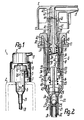
- an output device 1 which is to be attached to the neck 3 of a storage vessel 2 or the like, has a pump 4 designed as a thrust piston pump, which protrudes in or through the neck 3 with a fastening cap 5 is that the storage vessel 2 is tightly closed.
- a pump 4 designed as a thrust piston pump, which protrudes in or through the neck 3 with a fastening cap 5 is that the storage vessel 2 is tightly closed.
- the actuating head 7 projects partially into a cover cap 9 which receives the fastening cap 5 and the end of the pump housing 6 protruding therefrom, in which the actuating head 7 including the piston unit can be guided against rotation.
- the parts described lie in the central axis 10 of the thrust piston pump.
- the pump housing 6 is formed by a tubular cylinder housing 11 graduated in diameter and a sleeve-shaped cylinder cover 12 which is attached to the outer, further end of the cylinder housing 11 and has an annular collar 13 adjacent to its inner end face for sealing contact with the neck 3 of the vessel.
- the cylinder housing 11 forms a pump cylinder 14, the inner surface of which is provided as a piston raceway 15 for a pump piston 17 arranged at the inner end of the piston unit 16.
- the pump piston 17 has a sleeve-shaped piston lip 19 which is widened in the shape of a truncated cone in the direction of arrow 18 of the pump stroke, with its annular end edge, which at the same time forms the inner end of the piston unit 16 or the pump piston 17, it is guided in a sealed manner on the piston raceway 15.
- the pump piston 17 delimits a pump chamber 20 with the cylinder 14.
- the inner end of the cylinder housing 11 merges via a frustoconically tapered section into a reduced-diameter intake port 21, in which an intake valve arrangement 22 is provided which, in terms of action, comprises two intake valves 23, 24.
- the suction valves 23, 24 have separate, oppositely arranged valve seats 25, 26, but a single, common valve body 27, which in the exemplary embodiment shown is a ball that can move freely between the two valve seats 25, 26 in a valve chamber 28, but also by a valve body of a different spatial shape can be formed, which is then expediently guided between its functional positions in a predetermined position.
- valve seat 25 is the same, namely expanded in the shape of a truncated cone in the opposite or opposite direction, the valve chamber 28 being continuously cylindrical between the valve seats.
- the valve seat 26, which is closer to the pump chamber 20 and which is formed by a truncated cone jacket which projects freely in the direction of the pump chamber 20 and is formed in one piece with the cylinder housing 11 and lies in the region of the associated end of the intake port 21, limits the pump chamber 20 practically into the pump chamber 20 and the valve opening 29 lying in the central axis 10, which in the manner of an impact jet nozzle narrows conically in the shape of a truncated cone to the inside of the valve chamber 28 and is directed symmetrically against the valve body 27 such that a medium jet coming from it immediately throws the valve body 27 against the valve seat 25 .
- the other valve seat 25, whose valve opening is larger than the valve opening. 29 may be formed by a sleeve-shaped insert body 30, which is inserted into the inlet connector 21 from the end thereof and the outside diameter of which is substantially equal to the inside diameter of the valve chamber 28.
- the insert body 30 serves at the same time to fasten an intake hose 31 by insertion, this intake hose 31 extending directly in the vicinity of the bottom of the storage vessel 20 and limiting the intake duct of the pump 4 for the top position shown in FIGS. 1 to 3.
- the suction duct 33 for the head position turned around is formed by at least one, in particular a plurality of openings in the jacket of the cylinder 14 which are evenly distributed over the circumference and which penetrate the piston raceway 15 in a region which is directly adjacent to the contact edge of the piston lip 19 when the pump piston 17 is in the initial position lies.
- the suction channel 33 or the associated openings penetrate the outer circumference of the cylinder 14 in a region which, when the dispensing device 1 is mounted, is located directly adjacent to the neck 3 in the storage vessel 2, i.e. when the head is in the then approximately deepest area of the interior of the storage vessel intended for receiving the medium 2 lies, so that the storage vessel 2 can be emptied essentially completely with the pump 4 even in the top position.
- the piston unit 16 has a piston sleeve 34, which is formed in one piece with the sleeve-shaped hollow pump piston 17 and adjoins its rear end, which is also closed sleeve-shaped and extends outward beyond the outside of the pump housing 6 or the cylinder cover 12 into the outer part of the actuating head 7 enough.
- the piston sleeve 34 delimits an outlet channel 35 lying in it, which connects the pump chamber 20 through the pump piston 17 with the interposition of a mechanically opening outlet valve 36 with the outlet opening 8.
- the annular valve seat 37 of the outlet valve 36 lying approximately in the middle of the length of the piston sleeve 34 or in the region of the inner end of the cylinder cover 12 is formed by an annular bead 38 of the piston sleeve 34 protruding radially inwards.
- the valve body 39 of the outlet valve 36 lies completely inside the piston sleeve 34 essentially on the side of the valve seat 37 facing the pump chamber 20, its valve-conical surface 40 tapering outward in the shape of a truncated cone being formed by the end face of the collar-shaped valve body 39 facing away from the pump chamber 20.
- the valve body 39 is formed in one piece with a valve stem 41 which is slotted in the longitudinal direction or axially on the circumference in order to release the outlet channel 45 such that it is cross-shaped, for example, in cross-section and over its length has going cylindrical peripheral surfaces.
- the valve stem 41 is slidably guided in the outer piston neck 56 of the piston sleeve 34, which engages in the actuating head 7, parallel to the central axis 10, this cylindrical sliding surface of the piston sleeve 34 in the direction of the valve seat 27 becoming a frustoconically widened inner surface, so that the Execute valve stem 41 at least in the open position of the outlet valve 36 within narrow limits and allow the valve body 39 to align precisely with the valve seat 37.
- a return spring in the form of, for example, a helical compression spring located within the cylinder housing 11 is provided, which penetrates the pump piston 17 and, up to the valve body 39, the piston sleeve 34 and on the end face of the valve body 39 which is remote from the closing surface 40 and is perpendicular to the central axis 10 is supported.
- the valve body 39 On this end face, the valve body 39 has a protruding projection for centered engagement in the return spring 42.
- the other end of the return spring 42 lying in the pump chamber 20 is supported on an axially secured intermediate body 43 inserted directly adjacent to the valve opening 29 in the cylinder housing 11, which also engages with a centering projection in the return spring 42, this centering projection in every position of the pump piston 17 in. This protrudes.
- valve stem 41 extends to the outer end of the piston neck 56 such that the end face 44 of the valve stem 41 lies in the plane of the outer end face of the piston sleeve 34.
- the piston neck 56 of the piston sleeve 34 with a slight sliding fit is surrounded by a sliding sleeve 45 of the actuating head 7, this sliding sleeve 45 protruding into the pump housing 6 at every position of the piston unit 16 and opposite the actuating part designed to grip over the cylinder cover 12 in a cap-like manner of the actuating head 7 has a significantly smaller outer diameter.
- the piston sleeve 34 and the sliding sleeve 45 can engage in one another via an annular collar and an annular groove in such a way that they can be moved against one another in a limited manner between two axial end positions;
- the annular collar 46 engaging in an inner groove of the sliding sleeve 45 is provided on the outer circumference of the piston neck 56 near the outer end of the piston sleeve 34.
- the actuating head 7 rests with the free end of an inner punch 47 provided in the central axis 10, which lies in an annular section 48 of the outlet channel 35, from which the channel section leading to the outlet opening 8, for example perpendicular to the central axis 10, extends.
- the intermediate body 43 forms an annular inner shoulder 49 opposite the pump piston 19, which forms the end of the piston raceway 15 and directly adjoins it.
- the pump piston 17 runs with its front end face against this inner shoulder 49, the intermediate body 43 engaging with an annular shoulder projecting over the inner shoulder 49 into the piston lip 19 of the pump piston 17 in such a way that it bears against the inner surface of the piston lip 19 and this supports against deformation.
- the pump described works according to the following method: If the actuating head 7 is pressed down manually against the force of the return spring 42, the piston lip 19 passes over the openings in the piston raceway 15 of the suction channel 33 at the beginning of this movement, so that it is closed in the manner of a slide control ; in addition, the valve assembly 22 is already closed at the beginning of this movement in that the valve body 27 lies tightly against the valve seat 25. During the further movement, a pressure builds up in the pump chamber 20 until the pump piston 17 has reached the inner shoulder 49 and the pump piston 17 is thereby fixed against further movements in the direction of the pump stroke 18.
- the actuating head 7 is moved further in relation to the piston unit 16 or the valve seat 37 by the valve opening stroke 50 in the direction of arrow 18 of the pump stroke, such that the valve body 39 according to FIG. 3 against the force of the return spring 42 transferred to its open position and the outlet valve 36 was opened.
- the medium under pressure in the pump chamber 20 can thereby be discharged via the outlet valve 36 and through the outlet opening 8 of the actuating head 7.
- the manual return of the actuating head 7 initiates the return stroke, in which the valve body 39 is first moved into the closed position by the return spring 42, taking the actuating head 7 with it, after which the rest of the piston unit 16, i.e.
- valve closing surface 40 is seated on the valve seat 37
- Pump piston 17 is taken and transferred to the starting position.
- the valve body 27 of the valve assembly 22 lifts off the valve seat 25, the flow conditions being provided in such a way that the valve body 27 cannot get into its second closed position, namely into the closed position adjacent to the valve seat 26, so that 32 medium into the through the suction channel Pump chamber 20 is sucked.
- the next pump stroke can then be carried out in the manner described.
- valve body 27 falls under the weight force acting on it into the valve seat 26 and the medium located in the storage vessel 2 collects in the head space surrounding the pump 4 of the storage vessel 2 in such a way that the suction channel 33 is immersed in the medium, while the suction opening of the suction channel 32 associated with the storage vessel is not immersed.
- an air compensation channel 51 connecting this space with the atmosphere is provided, which has an annular gap through an inner sleeve 52 and the piston sleeve 34 passing through it Sliding sleeve 45 is limited; the inner sleeve 52 is provided on the cylinder cover 12 and projects freely into the cylinder housing 11.
- an air compensation valve 53 is provided for the air compensation duct 51, which valve is hermetically closed when the pump is in the initial position and mechanically opened when the pump is actuated becomes.
- This air balancing valve 53 is formed by an outwardly conically tapered closing surface 54 of the pump piston 17 which adjoins the piston lip 19 and which, as valve seat 55, is assigned to the inner end of the inner sleeve 52.
- the air compensation duct 51 is also provided for the air or pressure compensation in the storage vessel 2, for which purpose an air compensation connection between the interior of the pump housing 6, i.e. between the part of this housing interior which is connected to the air compensation duct 51 and is separated from the pump chamber 20 by the pump piston 17 or the piston lip 19 and the interior of the storage vessel 2.
- This air balancing connection is closed when the pump piston 17 is at rest or in the initial position, as is the air balancing valve 53, by slide control; namely, it is formed by the intake duct 33.
- the air compensation connection to the named part of the housing interior is opened and thereby connected to the air compensation duct 51 or open to it.
- the air balancing connection mentioned is closed again;
- two air compensation valves namely the air compensation valve 53 and the slide-controlled valve, are provided in series with respect to the interior of the storage vessel 2, which is formed by the interaction between the intake duct 33 and the piston lip 19.
- the suction channel 33 can thus be very close to the area of the storage vessel 2, which forms its deepest area when the head is in the top position.
- the piston unit 16 only needs to have a single slide and piston lip 19, which opens the air compensation connection formed by the suction channel 33 at the beginning of the closing of the suction channel 33 with respect to the pump chamber 20.
- the entire empty space of the pump housing 6, which is separated from the sealing edge of the pump piston 17 with respect to the pump chamber 20, is sealed tightly with respect to the storage vessel 2 when the piston unit 16 is in the initial position.
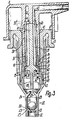
- FIGS. 4 and 5 the same reference numerals as in FIGS. 1 to 3, but with the index “a”, are used for corresponding parts.
- the two valve seats 25a, 26a of the valve arrangement 22a have different cone angles for the intake duct 32a, both of which are formed in one piece with the cylinder housing 11. It is thus conceivable to design the valve seat 26a and the valve opening 29a such that the valve body 27a is held in the head position according to FIG. 5 with a predetermined clamping or detent in the valve seat 26a. This stop is then in the pump chamber 20a when a corresponding upper pressure is reached overcome during the pumping stroke, so that the valve body 27a is suddenly transferred into its closed position on the valve seat 25a.
- the pump piston 17a is formed with an elastically compressible piston neck 34a, which forms the closing spring for the outlet valve 36a.
- the end of the piston neck 34a facing away from the piston lip 19a is clamped in a sealed manner in the valve stem 41a, this valve stem 41a simultaneously forming the piston rod or the pump tappet receiving the actuating head (not shown in more detail).
Landscapes
- Reciprocating Pumps (AREA)
- Closures For Containers (AREA)
- Details Of Reciprocating Pumps (AREA)
Claims (10)
Applications Claiming Priority (2)
| Application Number | Priority Date | Filing Date | Title |
|---|---|---|---|
| DE19853517558 DE3517558A1 (de) | 1985-05-15 | 1985-05-15 | Handbetaetigte ausgabeeinrichtung fuer medien |
| DE3517558 | 1985-05-15 |
Publications (3)
| Publication Number | Publication Date |
|---|---|
| EP0201701A2 EP0201701A2 (fr) | 1986-11-20 |
| EP0201701A3 EP0201701A3 (en) | 1987-10-07 |
| EP0201701B1 true EP0201701B1 (fr) | 1990-04-25 |
Family
ID=6270835
Family Applications (1)
| Application Number | Title | Priority Date | Filing Date |
|---|---|---|---|
| EP86104326A Expired - Lifetime EP0201701B1 (fr) | 1985-05-15 | 1986-03-27 | Dispositif de pulvérisation manuel |
Country Status (4)
| Country | Link |
|---|---|
| US (2) | US4776498A (fr) |
| EP (1) | EP0201701B1 (fr) |
| JP (1) | JPS61263668A (fr) |
| DE (2) | DE3517558A1 (fr) |
Cited By (1)
| Publication number | Priority date | Publication date | Assignee | Title |
|---|---|---|---|---|
| US6055979A (en) * | 1996-04-02 | 2000-05-02 | Ing. Erich Pfeiffer Gmbh | Dosing and discharging device for flowable media including powder/air dispersions |
Families Citing this family (59)
| Publication number | Priority date | Publication date | Assignee | Title |
|---|---|---|---|---|
| DE3513575A1 (de) * | 1985-04-16 | 1986-10-16 | Ing. Erich Pfeiffer GmbH & Co KG, 7760 Radolfzell | Handbetaetigte ausgabeeinrichtung fuer medien |
| DE3715300A1 (de) * | 1987-05-08 | 1988-11-24 | Pfeiffer Erich Gmbh & Co Kg | Austragvorrichtung fuer medien |
| FR2627708B1 (fr) * | 1988-02-26 | 1990-06-08 | Valois Sa | Dispositif pour permettre l'emploi en toutes positions d'une valve de vaporisateur |
| EP0345132B1 (fr) * | 1988-06-02 | 1993-09-22 | Societe Technique De Pulverisation Step | Pompe-doseuse à précompression à amorçage amélioré |
| DE3836236A1 (de) * | 1988-10-25 | 1990-04-26 | Siegfried Kroschel | Vorrichtung zum handbetaetigten verspruehen einer fluessigkeit |
| US4938392A (en) * | 1988-11-29 | 1990-07-03 | Su Cheng Yuan | Anti-leakage structure for a liquid atomizer |
| GB8920365D0 (en) * | 1989-09-08 | 1989-10-25 | Warren William E | Check valves |
| CA2027786C (fr) * | 1989-10-31 | 1997-01-28 | Koichi Sugita | Contenant muni d'une pompe |
| EP0446513B1 (fr) * | 1990-03-16 | 1994-11-02 | Kabushiki Kaisha Top | Pompe |
| JPH0526857U (ja) * | 1991-03-13 | 1993-04-06 | 株式会社吉野工業所 | 液体噴出器の押下げヘツド |
| US5348189A (en) * | 1991-04-10 | 1994-09-20 | Bespak Plc | Air purge pump dispenser |
| US5192006A (en) * | 1991-05-01 | 1993-03-09 | Risdon Corporation | Low profile pump |
| DE9106675U1 (de) * | 1991-05-31 | 1991-07-18 | CWF-Chemie Frankfurt GmbH, 6457 Maintal | Seifenspender |
| IT1251684B (it) * | 1991-10-11 | 1995-05-19 | Carlo Mancini | Pompetta ad azionamento manuale per dispensare sostanze liquide o cremose a pressione costante e prestabilita. |
| US5431155A (en) * | 1992-06-03 | 1995-07-11 | Elettro Plastica S.P.A. | Single-dose nasal dispenser for atomized liquid drugs |
| IT1260526B (it) * | 1992-06-03 | 1996-04-09 | Andrea Marelli | Erogatore nasale monodose di farmaci liquidi polverizzati |
| US5284276A (en) * | 1992-10-21 | 1994-02-08 | Bespak Plc | Pump dispenser with combined inlet and outlet ports |
| US5350116A (en) * | 1993-03-01 | 1994-09-27 | Bespak Plc | Dispensing apparatus |
| US5458289A (en) * | 1993-03-01 | 1995-10-17 | Bespak Plc | Liquid dispensing apparatus with reduced clogging |
| USD356947S (en) | 1993-10-28 | 1995-04-04 | L'oreal S.A. | Dispenser |
| DE4400944A1 (de) * | 1994-01-14 | 1995-07-20 | Ursatec Verpackung Gmbh | Saug-Druckpumpe für Fluidbehälter |
| US5664706A (en) * | 1994-10-13 | 1997-09-09 | Bespak Plc | Apparatus for dispensing liquid in aerosol spray form |
| USD396186S (en) | 1994-11-10 | 1998-07-21 | Trevor Fiore | Pump spray bottle |
| US6050457A (en) * | 1995-12-06 | 2000-04-18 | The Procter & Gamble Company | High pressure manually-actuated spray pump |
| US5850947A (en) * | 1996-07-15 | 1998-12-22 | Kim; Phillip S. | Invertible and multi-directional fluid delivery device |
| DE19723133A1 (de) * | 1997-06-03 | 1998-12-10 | Caideil M P Teoranta Tourmakea | Austragvorrichtung für Medien |
| USD441654S1 (en) | 1997-04-18 | 2001-05-08 | Owens-Illinois Closure Inc. | Liquid dispenser |
| DE19727356B4 (de) * | 1997-06-27 | 2006-04-20 | Ing. Erich Pfeiffer Gmbh | Spender für Medien |
| US6209759B1 (en) | 1997-07-04 | 2001-04-03 | Valois S.A. | Hand-operated pump with a free floating sleeve piston |
| USD416489S (en) | 1997-09-24 | 1999-11-16 | Owens-Illinois Closure Inc. | Actuator for a liquid dispenser |
| US5979712A (en) * | 1997-10-24 | 1999-11-09 | Monturas, S.A. | Upright/inverted sprayer |
| US5899363A (en) * | 1997-12-22 | 1999-05-04 | Owens-Illinois Closure Inc. | Pump dispenser having a locking system with detents |
| DE10015968A1 (de) * | 2000-03-30 | 2001-10-04 | Pfeiffer Erich Gmbh & Co Kg | Spender für Medien |
| FR2811644B1 (fr) * | 2000-07-12 | 2002-09-06 | Oreal | Dispositif pour le conditionnement et la distribution dosee d'un produit liquide |
| FR2832699B1 (fr) * | 2001-11-23 | 2004-01-30 | Oreal | Dispositif pour le conditionnement et la distribution dosee d'un produit liquide |
| GB0208806D0 (en) * | 2002-04-17 | 2002-05-29 | Rieke Corp | Dispenser pumps |
| AU2003238933A1 (en) | 2002-06-06 | 2003-12-22 | Kanfer, Joseph | Dip tube for use with a pump dispenser |
| AU2003260367A1 (en) * | 2002-08-06 | 2004-02-25 | Glaxo Group Limited | A dispenser |
| WO2004022451A2 (fr) * | 2002-09-06 | 2004-03-18 | Leafgreen Limited | Ameliorations apportees ou associees a des tubes plongeurs |
| FR2849476B1 (fr) * | 2002-12-26 | 2006-04-28 | Rexam Dispensing Sys | Pompe a poussoir, notamment pour produit cosmetique |
| US7503466B2 (en) * | 2003-04-11 | 2009-03-17 | L'oreal | Pump and receptacle fitted therewith |
| US7325704B2 (en) * | 2003-09-10 | 2008-02-05 | Rieke Corporation | Inverted dispensing pump with vent baffle |
| CN100413596C (zh) * | 2003-09-17 | 2008-08-27 | 丁要武 | 小出量乳液泵 |
| GB0402695D0 (en) * | 2004-02-06 | 2004-03-10 | Glaxo Group Ltd | A metering pump system |
| DE102004048248B3 (de) * | 2004-10-04 | 2006-02-09 | Seaquist Perfect Dispensing Gmbh | Adapter für eine handbetätigte Abgabevorrichtung für Flüssigkeitsbehälter |
| US7607592B1 (en) | 2004-11-08 | 2009-10-27 | Kim Sang B | Accessories for water and beverage bottles |
| CN100453187C (zh) * | 2006-05-09 | 2009-01-21 | 黄建壮 | 手扣式微型喷雾器 |
| USD590658S1 (en) | 2007-03-05 | 2009-04-21 | Richard Pola & Associates, Inc. | Cup with spritzing mechanism |
| GB0815881D0 (en) | 2008-09-01 | 2008-10-08 | Rieke Corp | Liquid dosing devices |
| US9433960B2 (en) * | 2008-09-01 | 2016-09-06 | Rieke Corporation | Liquid dosing devices |
| IT1393854B1 (it) * | 2009-04-01 | 2012-05-11 | Emsar Spa | Dispenser. |
| US8418889B2 (en) * | 2010-01-11 | 2013-04-16 | Rieke Corporation | Inverted dispenser pump with liquid inlet cup valve |
| GB201000601D0 (en) | 2010-01-14 | 2010-03-03 | Rieke Corp | Pump dispensers |
| GB201011143D0 (en) | 2010-07-01 | 2010-08-18 | Rieke Corp | Dispensers |
| GB201011144D0 (en) | 2010-07-01 | 2010-08-18 | Rieke Corp | Dispensers |
| KR101590865B1 (ko) * | 2014-08-28 | 2016-02-02 | (주)연우 | 디스펜서 용기 |
| US20180132671A1 (en) | 2015-05-22 | 2018-05-17 | Clay Callicoat | Liquid product pump devices, systems, and methods of using the same |
| CN110664089A (zh) * | 2019-10-15 | 2020-01-10 | 中山市美捷时包装制品有限公司 | 一种弹簧外置型香水泵结构 |
| US20220397106A1 (en) * | 2021-06-10 | 2022-12-15 | Kevin Imai | Fluid Pumping Device |
Family Cites Families (22)
| Publication number | Priority date | Publication date | Assignee | Title |
|---|---|---|---|---|
| US2332007A (en) * | 1941-03-14 | 1943-10-19 | Arthur L Parker | Sump selector valve for fuel tanks |
| US3185354A (en) * | 1963-06-04 | 1965-05-25 | Valve Corp Of America | Pump dispensing device for liquid containers |
| DE1201684B (de) * | 1964-01-28 | 1965-09-23 | Erich Pfeiffer K G Metallwaren | In einem Gefaess eingebaute einfach wirkende handbetaetigte Schubkolbenpumpe |
| US3257961A (en) * | 1964-04-23 | 1966-06-28 | Holmes T J Co | Pump |
| US3211346A (en) * | 1964-07-15 | 1965-10-12 | Meshberg Philip | Pump-type dispenser |
| US3379136A (en) * | 1966-08-26 | 1968-04-23 | Diamond Int Corp | Liquid dispenser |
| DE1302372C2 (de) * | 1967-01-17 | 1978-06-08 | Pfeiffer Zerstäuber-Vertriebsgesellschaft mbH & Co KG, 7760 Radolfzell | In einem gefaess eingebaute einfachwirkende handbetaetigte schubkolbenpumpe |
| US3414169A (en) * | 1967-02-17 | 1968-12-03 | Diamond Int Corp | Liquid dispenser |
| US3556353A (en) * | 1968-04-17 | 1971-01-19 | Harry A Echols | Apparatus for dispensing liquid |
| US3640470A (en) * | 1969-02-26 | 1972-02-08 | Lion Fat Oil Co Ltd | Spray pump |
| US3724726A (en) * | 1972-01-05 | 1973-04-03 | Lion Fat Oil Co Ltd | Pump for spraying |
| US3908870A (en) * | 1973-11-15 | 1975-09-30 | Yoshino Kogyosho Co Ltd | Manual-type miniature atomizer |
| JPS5620052Y2 (fr) * | 1975-07-21 | 1981-05-13 | ||
| US4056216A (en) * | 1976-04-13 | 1977-11-01 | The Risdon Manufacturing Company | Liquid dispensing pump automatically sealable against leakage |
| US4117957A (en) * | 1977-04-11 | 1978-10-03 | George Duffey | Atomizer valve assembly |
| NL179791C (nl) * | 1977-05-12 | 1986-11-17 | Yoshino Kogyosho Co Ltd | Zowel rechtop als in omgekeerde stand te gebruiken verstuiver. |
| JPS6026830Y2 (ja) * | 1978-03-16 | 1985-08-13 | 株式会社吉野工業所 | 手動式噴霧器 |
| EP0016839B1 (fr) * | 1978-06-07 | 1982-10-20 | Yoshino Kogyosho Co., Ltd. | Vaporisateur utilisable a la fois en position droite et renversee |
| DE2919686A1 (de) * | 1979-05-16 | 1981-03-12 | Seltmann, Hans-Jürgen, 2000 Hamburg | Ausgabepumpe, insbesondere zum zerstaeuben von fluessigkeiten, welche auch in umgekehrter position arbeitet. |
| US4286736A (en) * | 1980-02-20 | 1981-09-01 | Diamond International Corporation | Liquid Dispenser |
| DE3025725C2 (de) * | 1980-07-08 | 1985-11-07 | Deutsche Präzisions-Ventil GmbH, 6234 Hattersheim | Sprühventilanordnung |
| DE3045565C2 (de) * | 1980-12-03 | 1983-01-20 | Deutsche Präzisions-Ventil GmbH, 6234 Hattersheim | Vorrichtung zum Versprühen einer Flüssigkeit aus einem Behälter |
-
1985
- 1985-05-15 DE DE19853517558 patent/DE3517558A1/de not_active Withdrawn
-
1986
- 1986-03-27 EP EP86104326A patent/EP0201701B1/fr not_active Expired - Lifetime
- 1986-03-27 DE DE8686104326T patent/DE3670619D1/de not_active Expired - Lifetime
- 1986-04-23 US US06/855,505 patent/US4776498A/en not_active Expired - Lifetime
- 1986-05-09 JP JP61105082A patent/JPS61263668A/ja active Pending
-
1988
- 1988-08-03 US US07/227,652 patent/US4958752A/en not_active Expired - Lifetime
Cited By (1)
| Publication number | Priority date | Publication date | Assignee | Title |
|---|---|---|---|---|
| US6055979A (en) * | 1996-04-02 | 2000-05-02 | Ing. Erich Pfeiffer Gmbh | Dosing and discharging device for flowable media including powder/air dispersions |
Also Published As
| Publication number | Publication date |
|---|---|
| EP0201701A2 (fr) | 1986-11-20 |
| DE3670619D1 (de) | 1990-05-31 |
| DE3517558A1 (de) | 1986-11-20 |
| US4776498A (en) | 1988-10-11 |
| EP0201701A3 (en) | 1987-10-07 |
| JPS61263668A (ja) | 1986-11-21 |
| US4958752A (en) | 1990-09-25 |
Similar Documents
| Publication | Publication Date | Title |
|---|---|---|
| EP0201701B1 (fr) | Dispositif de pulvérisation manuel | |
| EP0199142B1 (fr) | Dispositif de pulvérisation manuel | |
| DE1500597C3 (de) | Tauchrohrzerstäuber | |
| DE3050097C2 (de) | Zerstäuberpumpe für Flüssigkeiten | |
| DE2001921A1 (de) | Hin- und herbewegte Fluessigkeitsabgabepumpe | |
| DE2612192C3 (de) | Flüssigkeitszerstäuber | |
| DE3018840C2 (de) | Zerstäuber für Flüssigkeiten | |
| DE2943074C2 (de) | In einen Behälterhals einsetzbarer Flüssigkeitszerstäuber | |
| DE2216525C3 (de) | Flüssigkeitszerstäuber | |
| EP0184686B1 (fr) | Pompe à piston pour distributeur de substance active | |
| DE3722469A1 (de) | Handbetaetigbare austragvorrichtung fuer medien | |
| DE19723133A1 (de) | Austragvorrichtung für Medien | |
| DE2902624A1 (de) | Zerstaeuberpumpe | |
| DE10200593A1 (de) | Betätigungskopf einer Saug-Druck-Pumpe zum Ausspritzen eines Produkts aus einem Behältnis | |
| DE2223471B2 (de) | Ventil zum einsatz in einen behaelter, insbesondere in einen aerosol- behaelter | |
| EP0289854B1 (fr) | Distributeur de fluides | |
| EP0901836A2 (fr) | Distributeur de fluide | |
| EP0887112B1 (fr) | Distributeur de fluides | |
| DE3624657A1 (de) | Abgabepumpe fuer ein stroemungsmittel aus einem behaelter | |
| DE3834091C2 (fr) | ||
| DE4005529A1 (de) | Austragkopf fuer medien | |
| EP0388651B1 (fr) | Dispositif pour décharger un fluide | |
| DE2705071A1 (de) | Von hand betaetigbare spruehvorrichtung mit automatischer behaelterentlueftung | |
| EP0849005A1 (fr) | Dispositif batteur pneumatique | |
| DE1703416C3 (de) | Zerstäuberkolbenpumpe |
Legal Events
| Date | Code | Title | Description |
|---|---|---|---|
| PUAI | Public reference made under article 153(3) epc to a published international application that has entered the european phase |
Free format text: ORIGINAL CODE: 0009012 |
|
| AK | Designated contracting states |
Kind code of ref document: A2 Designated state(s): CH DE FR GB IT LI NL |
|
| PUAL | Search report despatched |
Free format text: ORIGINAL CODE: 0009013 |
|
| RHK1 | Main classification (correction) |
Ipc: B65D 47/34 |
|
| AK | Designated contracting states |
Kind code of ref document: A3 Designated state(s): CH DE FR GB IT LI NL |
|
| 17P | Request for examination filed |
Effective date: 19880310 |
|
| 17Q | First examination report despatched |
Effective date: 19881115 |
|
| GRAA | (expected) grant |
Free format text: ORIGINAL CODE: 0009210 |
|
| AK | Designated contracting states |
Kind code of ref document: B1 Designated state(s): CH DE FR GB IT LI NL |
|
| GBT | Gb: translation of ep patent filed (gb section 77(6)(a)/1977) | ||
| REF | Corresponds to: |
Ref document number: 3670619 Country of ref document: DE Date of ref document: 19900531 |
|
| ET | Fr: translation filed | ||
| ITF | It: translation for a ep patent filed | ||
| PLBE | No opposition filed within time limit |
Free format text: ORIGINAL CODE: 0009261 |
|
| STAA | Information on the status of an ep patent application or granted ep patent |
Free format text: STATUS: NO OPPOSITION FILED WITHIN TIME LIMIT |
|
| ITTA | It: last paid annual fee | ||
| 26N | No opposition filed | ||
| PGFP | Annual fee paid to national office [announced via postgrant information from national office to epo] |
Ref country code: GB Payment date: 19930310 Year of fee payment: 8 |
|
| PGFP | Annual fee paid to national office [announced via postgrant information from national office to epo] |
Ref country code: FR Payment date: 19930315 Year of fee payment: 8 |
|
| PGFP | Annual fee paid to national office [announced via postgrant information from national office to epo] |
Ref country code: NL Payment date: 19930331 Year of fee payment: 8 |
|
| PGFP | Annual fee paid to national office [announced via postgrant information from national office to epo] |
Ref country code: CH Payment date: 19930419 Year of fee payment: 8 |
|
| PGFP | Annual fee paid to national office [announced via postgrant information from national office to epo] |
Ref country code: DE Payment date: 19930519 Year of fee payment: 8 |
|
| PG25 | Lapsed in a contracting state [announced via postgrant information from national office to epo] |
Ref country code: GB Effective date: 19940327 |
|
| PG25 | Lapsed in a contracting state [announced via postgrant information from national office to epo] |
Ref country code: LI Effective date: 19940331 Ref country code: CH Effective date: 19940331 |
|
| PG25 | Lapsed in a contracting state [announced via postgrant information from national office to epo] |
Ref country code: NL Effective date: 19941001 |
|
| NLV4 | Nl: lapsed or anulled due to non-payment of the annual fee | ||
| GBPC | Gb: european patent ceased through non-payment of renewal fee |
Effective date: 19940327 |
|
| PG25 | Lapsed in a contracting state [announced via postgrant information from national office to epo] |
Ref country code: FR Effective date: 19941130 |
|
| REG | Reference to a national code |
Ref country code: CH Ref legal event code: PL |
|
| PG25 | Lapsed in a contracting state [announced via postgrant information from national office to epo] |
Ref country code: DE Effective date: 19941201 |
|
| REG | Reference to a national code |
Ref country code: FR Ref legal event code: ST |
|
| PG25 | Lapsed in a contracting state [announced via postgrant information from national office to epo] |
Ref country code: IT Free format text: LAPSE BECAUSE OF NON-PAYMENT OF DUE FEES;WARNING: LAPSES OF ITALIAN PATENTS WITH EFFECTIVE DATE BEFORE 2007 MAY HAVE OCCURRED AT ANY TIME BEFORE 2007. THE CORRECT EFFECTIVE DATE MAY BE DIFFERENT FROM THE ONE RECORDED. Effective date: 20050327 |