EP0201734A1 - Equipement dans un terminal téléphonique pour abonnés pour la déconnexion d'une des deux sous-stations connectables alternativement et automatiquement par le central en cas d'une fermeture indésirée de boucle dans cette sous-station - Google Patents
Equipement dans un terminal téléphonique pour abonnés pour la déconnexion d'une des deux sous-stations connectables alternativement et automatiquement par le central en cas d'une fermeture indésirée de boucle dans cette sous-station Download PDFInfo
- Publication number
- EP0201734A1 EP0201734A1 EP86105012A EP86105012A EP0201734A1 EP 0201734 A1 EP0201734 A1 EP 0201734A1 EP 86105012 A EP86105012 A EP 86105012A EP 86105012 A EP86105012 A EP 86105012A EP 0201734 A1 EP0201734 A1 EP 0201734A1
- Authority
- EP
- European Patent Office
- Prior art keywords
- telephone line
- switch
- test
- station
- switching device
- Prior art date
- Legal status (The legal status is an assumption and is not a legal conclusion. Google has not performed a legal analysis and makes no representation as to the accuracy of the status listed.)
- Granted
Links
- 238000012360 testing method Methods 0.000 claims abstract description 54
- 238000000926 separation method Methods 0.000 claims abstract 2
- 238000004804 winding Methods 0.000 claims description 29
- 238000012806 monitoring device Methods 0.000 claims description 7
- 235000010678 Paulownia tomentosa Nutrition 0.000 claims description 2
- 240000002834 Paulownia tomentosa Species 0.000 claims description 2
- 239000004020 conductor Substances 0.000 abstract 1
- 238000001514 detection method Methods 0.000 description 4
- 238000010586 diagram Methods 0.000 description 3
- 238000012544 monitoring process Methods 0.000 description 3
- 239000003990 capacitor Substances 0.000 description 2
- 208000033748 Device issues Diseases 0.000 description 1
- 238000000034 method Methods 0.000 description 1
- 238000010998 test method Methods 0.000 description 1
Images


Classifications
-
- H—ELECTRICITY
- H04—ELECTRIC COMMUNICATION TECHNIQUE
- H04M—TELEPHONIC COMMUNICATION
- H04M3/00—Automatic or semi-automatic exchanges
- H04M3/22—Arrangements for supervision, monitoring or testing
- H04M3/26—Arrangements for supervision, monitoring or testing with means for applying test signals or for measuring
- H04M3/28—Automatic routine testing ; Fault testing; Installation testing; Test methods, test equipment or test arrangements therefor
- H04M3/30—Automatic routine testing ; Fault testing; Installation testing; Test methods, test equipment or test arrangements therefor for subscriber's lines, for the local loop
- H04M3/301—Circuit arrangements at the subscriber's side of the line
-
- H—ELECTRICITY
- H04—ELECTRIC COMMUNICATION TECHNIQUE
- H04M—TELEPHONIC COMMUNICATION
- H04M3/00—Automatic or semi-automatic exchanges
- H04M3/08—Indicating faults in circuits or apparatus
- H04M3/12—Marking faulty circuits "busy"; Enabling equipment to disengage itself from faulty circuits ; Using redundant circuits; Response of a circuit, apparatus or system to an error
Definitions
- the invention relates to a device on a telephone subscriber line for switching off one of two alternately automatically connectable microphone units from the switching center in the event of an unwanted loop closure in this microphone unit with the features from the preamble of patent claim 1.
- a disadvantage that arises here is that in the event of a short circuit in one of the two microphone units, this microphone unit remains automatically connected to the telephone line and the other microphone unit is permanently blocked.
- Such a short circuit can also be caused by the fact that, for example, the subscriber at one station forgets to put the receiver on the fork after the conversation has ended and the GU contact thus remains closed.
- the object underlying the invention was to provide a device on the subscriber line of a telephone system of the type explained above, with which it is possible to switch off this station from the switching center in the event of an unwanted loop closure in one of the two stations so that the other Intercom station can be connected to the telephone line again via the two-way switching device and thus conversations can be conducted from this other intercom station.
- this call station After eliminating the short circuit in the first call station, for example when the handset is on the hook again, this call station should be automatically reset to the state without access from the control center, in which it can also be connected to the telephone line again via the changeover switching device.
- a device for testing a telephone line between a switching center and a subscriber line from the switching center is known, with which the Checking the telephone line from the exchange is possible without involving the subscriber line in the test.
- This older device basically consists of two parts, namely a switchover device, with which the telephone line is disconnected from the subscriber line in response to a control signal given by the switching center via the line and is connected to its own test device, by means of which the test is then carried out. After completing the test, the telephone line is reconnected to the subscriber line.
- a test signal is sent from the test device via the telephone line to the two-way switching device and via this to the switch-off device for the intercom station, in which the unwanted loop is closed.
- this station is separated from the two-way switching device, so that from the other Call station can be held again.
- the short-circuit monitoring device After the first call station has been switched off, it is monitored with the aid of the short-circuit monitoring device whether the loop is closed again in it '; is eliminated, i.e. the receiver is replaced, for example. As soon as this is the case, the short-circuit monitoring device issues a reset signal to the controllable switching element, which has the result that the original state is restored, that is to say the relevant intercom station is switched on again to the changeover switching device, so that calls can also be made from it again can.
- bistable relays are used as controllable switching elements. Furthermore, it has proven to be advantageous if, according to patent claim 3, the supply voltages for the switch-off devices are supplied from the test device for the telephone line. If the supply voltages are then supplied to the device for generating the supply voltages for the test device according to claim 4 via the telephone line, the entire device is supplied with supply voltages via the telephone line and no separate voltage sources are required.
- the setting signals supplied to the switch-off devices are returned to the test device and trigger a test signal there, the frequency of which is assigned to the switched-off station.
- This test signal is sent to the exchange over the telephone line. returned so that it can be recognized exactly which of the two microphone units is an unwanted one Has loop closure and has been switched off.
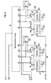
- a telephone line a, b coming from a switching center, not shown, is connected via switching contacts s to a further section of the telephone line a1, b1, which leads to a changeover switching device W, to the two microphone units SP1 and SP2 of the subscriber line are connected, via the Kirschaltvorrich - tung W can be connected alternately to the telephone line a1, b1.
- circuit parts arranged in the known changeover switching device which essentially consist of bistable relay circuits and loop current detection circuits, are not shown and are not described in more detail below.
- the output is all additionally connected to the wire al and the output B1 is connected to the wire b1 of the telephone line and the output b21 is separated from the wire bl.
- output a21 is also connected to wire a1 and output B2 to wire b1 of the telephone line, and output bll is separated from wire bl for this purpose.
- a device for testing the telephone line from the switching center which has a switchover device U and a test device P, is arranged in front of the changeover switching device W, as shown in FIG. 1.
- the switchover device U can be controlled on the one hand by a DC voltage control signal, for example an increase in the line voltage to 100 V, and on the other hand by an AC voltage signal.
- the switching device U contains a first control switch 2, which is connected to the two branches a1, b1 of the telephone line and which responds to an increase in the line voltage.
- the first control switch 2 can also be constructed in a manner known per se so that it responds to a brief reversal of the polarity of the DC line voltage.
- a second control switch 3 is connected via a rectifier bridge 4 to the secondary winding of a transformer U, the primary winding of which lies in the branch bl of the telephone line. The second control switch 3 responds to an AC voltage signal sent over the telephone line.
- Both control switches 2 and 3 are connected via a switching amplifier 5 to a first winding S1 of a bistable relay, the switching contacts s of which are arranged in the telephone line a, b from the switching center, in front of the switching device U.
- the first winding S1 of the bistable relay is activated, the telephone line a, b is separated via the switch contacts s from the section al, b1 leading to the changeover switching device W and the changeover device U and connected to a test device P.
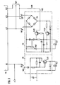
- the test device P contains a device 7 connected via a rectifier bridge 6 arranged to protect against reverse polarity in order to generate the supply voltages necessary for the test device. Furthermore, it contains several low-frequency oscillators, which are designated 8 in the drawing. The test signals run via low-frequency switching Devices 9, which are controlled by a clock 10 contained in a control device St. The test signals continue via an amplifier 11 and capacitors C1, C2 into the telephone line a, b.
- a call signal detection circuit 13 which controls a call signal switch 14, which in turn is connected to a switch-on element of the device 7 for generating the supply voltages.
- the call signal detection circuit 13 is connected to the telephone line a, b via capacitors C3 and C4.
- a timer switch 12 is connected to the telephone line a, b, which is connected to a second winding S2 of the bistable relay.
- a signal output of the clock generator 10 is also connected to the second winding S2 of the bistable relay.
- an output of the device 7 is connected to the wire b1 of the section of the telephone line al, b1 leading to the changeover switching device W.
- Circuits 15 and 25, respectively, are arranged between the two-way switching device W and the two intercom stations Spl and Sp2, by means of which a resettable disconnection of the intercom stations Sp1 and Sp2 from the two-way switching device W is possible.
- the switch-off device 15 assigned to the call station Sp1 has a bistable relay with a set winding K11 and a reset winding K12.
- the switch contacts k1 of this relay are connected in this way. orders that in the not set state, the output b11 of the changeover switching device W with the call station Spl and the output 81 via the set input Se1 with the Connect the set winding K11.
- a short-circuit monitoring circuit 16 which is explained in more detail below and which contains the reset winding K12, is on the one hand permanently connected to the call station Sp1 via a reset input RS1 and a line b10 and can be connected to the outputs a11, b11 of the changeover switching device W via the switch contacts k1.
- the switch-off device 25 assigned to the call station Sp2 has a bistable relay with a set winding K21 and a reset winding K22 and switch contacts k2, via which, in the non-set state, the output b21 with the call station Sp2 and the output B2 via the set input Se2 with the Set winding K21 is connected.
- the short-circuit monitoring device 26 has the reset winding K22 and is connected to the call station Sp2 via the reset input RS2 and can be connected to the outputs a21 and b21 of the changeover switching device W via the switch contacts k2.
- Supply voltage inputs of the shutdown devices 15 and 25 are connected via lines e11, e21 and e1 to the device 7 for generating the supply voltages in the test device P.
- the output B1 of the changeover switching device W is connected to the test device P via a line d1 in the manner shown in FIG. 1, while in an analogous manner the output 82 is also connected to the test device P via the line c1.
- the shutdown device 15 and the short-circuit monitoring circuit 16 are constructed analogously.
- the set winding K21 of the bistable relay is located in a circuit which contains a transistor Tr21, the base of which is connected to the output B2 of the changeover switching device W via the set input Se2.
- the reset winding K22 of the bistable relay is located in a circuit which, from a rectifier bridge 24 connected via the switching contacts k2 to the outputs a21 and b21 of the changeover switching device W, via a transistor Tr23, the relay winding K22 and a thyristor Th2 back to the rectifier bridge 24 running.
- a control circuit runs in parallel with this circuit and runs from the reset input RS2 via the transistor Tr22 and the transistor Tr23 to the rectifier bridge 24.
- This control signal activates the first control switch 2 in the switching device U and excites the relay winding S1 via the switching amplifier 5, so that the relay contacts s switch over and the test device P is thus connected to the telephone line a, b.
- a call signal is now sent out by the exchange, which is picked up by the call detection circuit 13.
- the device 7 for generating the supply voltages for the test device P is switched on via the call signal switch 14 and receives its supply voltage from the telephone line.
- the DC winding control signal also activates the set winding K21 and the switching contacts k2 are switched over.
- the shutdown device is now disconnected from output B2.
- the short-circuit monitoring device 26 is connected to the outputs a21 and b21 of the changeover switching device W instead of the intercom Sp2.
- the disconnection of the call station Sp2 is thus ended. Additional test cycles can now be carried out.
- the corresponding test signals can be emitted by the low-frequency oscillators 8, which are clocked by the clock generator 10 in such a way that a test cycle arises in which a predetermined number of low-frequency test signals are given via the amplifier 11 into the telephone line a, b at predetermined time intervals .
- the second relay winding S2 is then excited and the contacts s of the bistable relay switch again, so that the testing device P is again separated from the telephone line a, b and therefore the switching device U and the Kirschaltvor device W are connected to the exchange again.
- the timer 12 contained in the control device St serves primarily to ensure that after a certain time, regardless of whether the test cycle has been able to run properly, a reset signal is emitted by which the second relay winding S2 is energized and the test device is switched off.
- one end of the rectifier bridge 24 is connected via the intercom Sp2 to the line b20 leading to the reset input RS2 through the short circuit or loop short in the intercom station Sp2, while the other end of the rectifier bridge 24 is connected via the contact K2 to the output b21
- Changeover switching device W is connected, which, as explained above, is also connected to the wire bl of the telephone line in the idle state and receives a positive potential from there.
- a constant current with a low current intensity therefore constantly flows into the circuit characterized by the transistors Tr22 and Tr23. Due to the voltage conditions that arise, the thyristor Th2 remains blocked and no current flows through the reset winding K22 of the bistable relay.
- the shutdown device 25 is again connected to the output B2, so that a shutdown could be carried out again.
- FIG. 4 shows a variant of the device according to FIGS. 1 to 3, in which it is possible for the user of the subscriber line to switch off one of the two microphone units Spl or Sp2 when he has recognized that there is a short circuit.
- the changeover switching device W is briefly disconnected from the telephone line al, bl.
- the changeover switching device W is briefly disconnected from the telephone line al, bl.
- the supply voltage inputs of the shutdown devices 15 and 25 are connected to the telephone line al, bl.
- the line b3 is connected via a connecting line b30 to the wire b2 leading to the changeover switching device W.
- the changeover switch Res can also be arranged at another point on the telephone line, for example in section a, b of the switch contacts s (FIG. 1).
Landscapes
- Engineering & Computer Science (AREA)
- Signal Processing (AREA)
- Monitoring And Testing Of Exchanges (AREA)
- Interconnected Communication Systems, Intercoms, And Interphones (AREA)
- Interface Circuits In Exchanges (AREA)
Priority Applications (1)
| Application Number | Priority Date | Filing Date | Title |
|---|---|---|---|
| AT86105012T ATE40775T1 (de) | 1985-05-11 | 1986-04-11 | Einrichtung an einem fernsprechteilnehmeranschluss zur abschaltung einer von zwei wechselweise automatisch anschaltbaren sprechstellen von der vermittlungsstelle aus bei ungewolltem schleifenschluss in dieser sprechstelle. |
Applications Claiming Priority (2)
| Application Number | Priority Date | Filing Date | Title |
|---|---|---|---|
| DE3517088 | 1985-05-11 | ||
| DE3517088A DE3517088C1 (de) | 1985-05-11 | 1985-05-11 | Einrichtung an einem Fernsprech-Teilnehmeranschluss zur Abschaltung einer von zwei wechselweise automatisch anschaltbaren Sprechstellen von der Vermittlungsstelle aus bei ungewolltem Schleifenanschluss in dieser Sprechstelle |
Publications (2)
| Publication Number | Publication Date |
|---|---|
| EP0201734A1 true EP0201734A1 (fr) | 1986-11-20 |
| EP0201734B1 EP0201734B1 (fr) | 1989-02-08 |
Family
ID=6270537
Family Applications (1)
| Application Number | Title | Priority Date | Filing Date |
|---|---|---|---|
| EP86105012A Expired EP0201734B1 (fr) | 1985-05-11 | 1986-04-11 | Equipement dans un terminal téléphonique pour abonnés pour la déconnexion d'une des deux sous-stations connectables alternativement et automatiquement par le central en cas d'une fermeture indésirée de boucle dans cette sous-station |
Country Status (3)
| Country | Link |
|---|---|
| EP (1) | EP0201734B1 (fr) |
| AT (1) | ATE40775T1 (fr) |
| DE (2) | DE3517088C1 (fr) |
Citations (3)
| Publication number | Priority date | Publication date | Assignee | Title |
|---|---|---|---|---|
| DE1054123B (de) * | 1957-08-01 | 1959-04-02 | Erhard Kuehnl | Schaltungsanordnung fuer Fernsprechanschluesse, insbesondere Zweieranschluesse |
| DE1933717A1 (de) * | 1969-07-03 | 1971-01-21 | Standard Elek K Lorenz Ag | Schaltungsanordnung fuer einen Zweieranschluss in Fernmelde-,insbesondere Fernsprechvermittlungsanlagen |
| DE3140182A1 (de) * | 1980-10-09 | 1982-06-09 | ITALTEL Società Italiana Telecomunicazioni S.p.A., 20149 Milano | "schaltungsanordnung fuer ueber eine zweieranschlusseinrichtung an eine fernsprechvermittlungsstelle angeschlossene teilnehmer" |
Family Cites Families (1)
| Publication number | Priority date | Publication date | Assignee | Title |
|---|---|---|---|---|
| DE3513598A1 (de) * | 1985-04-16 | 1986-10-16 | Neumann Elektronik GmbH, 4330 Mülheim | Einrichtung zur pruefung einer fernmeldeleitung zwischen einer vermittlungsstelle und einem teilnehmeranschluss von der vermittlungsstelle aus |
-
1985
- 1985-05-11 DE DE3517088A patent/DE3517088C1/de not_active Expired
-
1986
- 1986-04-11 AT AT86105012T patent/ATE40775T1/de active
- 1986-04-11 EP EP86105012A patent/EP0201734B1/fr not_active Expired
- 1986-04-11 DE DE8686105012T patent/DE3662080D1/de not_active Expired
Patent Citations (3)
| Publication number | Priority date | Publication date | Assignee | Title |
|---|---|---|---|---|
| DE1054123B (de) * | 1957-08-01 | 1959-04-02 | Erhard Kuehnl | Schaltungsanordnung fuer Fernsprechanschluesse, insbesondere Zweieranschluesse |
| DE1933717A1 (de) * | 1969-07-03 | 1971-01-21 | Standard Elek K Lorenz Ag | Schaltungsanordnung fuer einen Zweieranschluss in Fernmelde-,insbesondere Fernsprechvermittlungsanlagen |
| DE3140182A1 (de) * | 1980-10-09 | 1982-06-09 | ITALTEL Società Italiana Telecomunicazioni S.p.A., 20149 Milano | "schaltungsanordnung fuer ueber eine zweieranschlusseinrichtung an eine fernsprechvermittlungsstelle angeschlossene teilnehmer" |
Also Published As
| Publication number | Publication date |
|---|---|
| EP0201734B1 (fr) | 1989-02-08 |
| DE3662080D1 (en) | 1989-03-16 |
| ATE40775T1 (de) | 1989-02-15 |
| DE3517088C1 (de) | 1986-09-04 |
Similar Documents
| Publication | Publication Date | Title |
|---|---|---|
| DE69904096T2 (de) | Fehlerschutzanordnung und -verfahren für elektrische Energieversorgungsanlagen | |
| EP2009765B1 (fr) | Dispositif d'alimentation en courant continue | |
| DE3044203A1 (de) | Automatisches nebenschlusssystem | |
| DE1512832B2 (de) | Schaltungsanordnung zum ueberbruecken eines fehlerhaften schleifenteils bei einem nachrichtenuebertragungssystem mit einem durchgeschleiften uebertragungsweg | |
| DE2933439C2 (de) | Verfahren zur Inbetriebnahme der beidseitigen Fernspeisung von Zwischenstellen einer Einrichtung der Nachrichtenübertragungstechnik | |
| DE3628922C2 (fr) | ||
| EP0201734B1 (fr) | Equipement dans un terminal téléphonique pour abonnés pour la déconnexion d'une des deux sous-stations connectables alternativement et automatiquement par le central en cas d'une fermeture indésirée de boucle dans cette sous-station | |
| EP0216096B1 (fr) | Dispositif pour la coupure par le central d'un poste branché involontairement sur la ligne dans une connexion à deux postes pouvant être branchés alternativement sur la ligne de façon automatique | |
| DE1155172B (de) | UEberwachungsschaltung fuer unbemannte gleichstrom-seriengespeiste Verstaerkerstationen | |
| DE303642C (fr) | ||
| DE3609979C2 (fr) | ||
| DE2931529A1 (de) | Teilnehmerseitiges datenuebertragungsgeraet, insbesondere fuer bildschirmtextbetrieb | |
| DE29702815U1 (de) | Umschalter | |
| DE3105592C2 (de) | Schaltungsanordnung zur beidseitigen Fernspeisung von Zwischenstellen einer Einrichtung der Nachrichtenübertragungstechnik | |
| DE3111400C2 (de) | Einrichtung zum Phasen-Differenzschutz von Elektromotoren | |
| DE2203539C3 (de) | Schaltungsanordnung für Fernsprechnebenstellenanlagen, insbesondere Reihenanlagen | |
| DE2138576B2 (de) | Umsetzerschaltung zum uebertragen von gleichstrom-telegraphiezeichen | |
| DE138898C (fr) | ||
| DE202004020401U1 (de) | Vorrichtung zur unterbrechungsfreien Stromversorgung | |
| DE3600864C2 (de) | Schaltungsanordnung mit Mitteln zur Herstellung der korrekten Polarität einer Fernsprechanschlußleitung | |
| DE439705C (de) | Tickereinrichtung fuer Fernsprechnebenstellenanlagen | |
| DE3400304A1 (de) | Schaltung zum erkennen eines schleifenzustands | |
| DE1105770B (de) | Verfahren und Einrichtung zur Signalkopplung in Beleuchtungs-straengen, vorwiegend fuer Untertageanlagen | |
| DE3937181A1 (de) | Wechselschaltvorrichtung fuer eine fernsprecheinrichtung zum anschluss zweier sprechstellen an eine gemeinsame fernsprechleitung | |
| DE4422976A1 (de) | Verfahren zur Überwachung einer Fernsprechleitung |
Legal Events
| Date | Code | Title | Description |
|---|---|---|---|
| PUAI | Public reference made under article 153(3) epc to a published international application that has entered the european phase |
Free format text: ORIGINAL CODE: 0009012 |
|
| AK | Designated contracting states |
Kind code of ref document: A1 Designated state(s): AT BE CH DE GB LI LU NL SE |
|
| 17P | Request for examination filed |
Effective date: 19861009 |
|
| 17Q | First examination report despatched |
Effective date: 19880706 |
|
| GRAA | (expected) grant |
Free format text: ORIGINAL CODE: 0009210 |
|
| AK | Designated contracting states |
Kind code of ref document: B1 Designated state(s): AT BE CH DE GB LI LU NL SE |
|
| PG25 | Lapsed in a contracting state [announced via postgrant information from national office to epo] |
Ref country code: SE Effective date: 19890208 Ref country code: NL Effective date: 19890208 Ref country code: BE Effective date: 19890208 |
|
| REF | Corresponds to: |
Ref document number: 40775 Country of ref document: AT Date of ref document: 19890215 Kind code of ref document: T |
|
| REF | Corresponds to: |
Ref document number: 3662080 Country of ref document: DE Date of ref document: 19890316 |
|
| GBT | Gb: translation of ep patent filed (gb section 77(6)(a)/1977) | ||
| NLV1 | Nl: lapsed or annulled due to failure to fulfill the requirements of art. 29p and 29m of the patents act | ||
| PLBE | No opposition filed within time limit |
Free format text: ORIGINAL CODE: 0009261 |
|
| STAA | Information on the status of an ep patent application or granted ep patent |
Free format text: STATUS: NO OPPOSITION FILED WITHIN TIME LIMIT |
|
| 26N | No opposition filed | ||
| PGFP | Annual fee paid to national office [announced via postgrant information from national office to epo] |
Ref country code: GB Payment date: 19930406 Year of fee payment: 8 |
|
| PGFP | Annual fee paid to national office [announced via postgrant information from national office to epo] |
Ref country code: CH Payment date: 19940317 Year of fee payment: 9 |
|
| PGFP | Annual fee paid to national office [announced via postgrant information from national office to epo] |
Ref country code: LU Payment date: 19940331 Year of fee payment: 9 |
|
| PG25 | Lapsed in a contracting state [announced via postgrant information from national office to epo] |
Ref country code: GB Effective date: 19940411 |
|
| PGFP | Annual fee paid to national office [announced via postgrant information from national office to epo] |
Ref country code: AT Payment date: 19940414 Year of fee payment: 9 |
|
| EPTA | Lu: last paid annual fee | ||
| PGFP | Annual fee paid to national office [announced via postgrant information from national office to epo] |
Ref country code: DE Payment date: 19940513 Year of fee payment: 9 |
|
| GBPC | Gb: european patent ceased through non-payment of renewal fee |
Effective date: 19940411 |
|
| PG25 | Lapsed in a contracting state [announced via postgrant information from national office to epo] |
Ref country code: LU Free format text: LAPSE BECAUSE OF NON-PAYMENT OF DUE FEES Effective date: 19950411 Ref country code: AT Effective date: 19950411 |
|
| PG25 | Lapsed in a contracting state [announced via postgrant information from national office to epo] |
Ref country code: LI Effective date: 19950430 Ref country code: CH Effective date: 19950430 |
|
| REG | Reference to a national code |
Ref country code: CH Ref legal event code: PL |
|
| PG25 | Lapsed in a contracting state [announced via postgrant information from national office to epo] |
Ref country code: DE Effective date: 19960103 |