EP0201737A2 - Viseur - Google Patents
Viseur Download PDFInfo
- Publication number
- EP0201737A2 EP0201737A2 EP86105110A EP86105110A EP0201737A2 EP 0201737 A2 EP0201737 A2 EP 0201737A2 EP 86105110 A EP86105110 A EP 86105110A EP 86105110 A EP86105110 A EP 86105110A EP 0201737 A2 EP0201737 A2 EP 0201737A2
- Authority
- EP
- European Patent Office
- Prior art keywords
- visor
- drill sleeve
- instrument
- radiation
- locking
- Prior art date
- Legal status (The legal status is an assumption and is not a legal conclusion. Google has not performed a legal analysis and makes no representation as to the accuracy of the status listed.)
- Withdrawn
Links
Images

Classifications
-
- A—HUMAN NECESSITIES
- A61—MEDICAL OR VETERINARY SCIENCE; HYGIENE
- A61B—DIAGNOSIS; SURGERY; IDENTIFICATION
- A61B17/00—Surgical instruments, devices or methods
- A61B17/16—Instruments for performing osteoclasis; Drills or chisels for bones; Trepans
- A61B17/17—Guides or aligning means for drills, mills, pins or wires
- A61B17/1725—Guides or aligning means for drills, mills, pins or wires for applying transverse screws or pins through intramedullary nails or pins
-
- A—HUMAN NECESSITIES
- A61—MEDICAL OR VETERINARY SCIENCE; HYGIENE
- A61B—DIAGNOSIS; SURGERY; IDENTIFICATION
- A61B17/00—Surgical instruments, devices or methods
- A61B17/16—Instruments for performing osteoclasis; Drills or chisels for bones; Trepans
- A61B17/17—Guides or aligning means for drills, mills, pins or wires
- A61B17/1703—Guides or aligning means for drills, mills, pins or wires using imaging means, e.g. by X-rays
-
- B—PERFORMING OPERATIONS; TRANSPORTING
- B23—MACHINE TOOLS; METAL-WORKING NOT OTHERWISE PROVIDED FOR
- B23Q—DETAILS, COMPONENTS, OR ACCESSORIES FOR MACHINE TOOLS, e.g. ARRANGEMENTS FOR COPYING OR CONTROLLING; MACHINE TOOLS IN GENERAL CHARACTERISED BY THE CONSTRUCTION OF PARTICULAR DETAILS OR COMPONENTS; COMBINATIONS OR ASSOCIATIONS OF METAL-WORKING MACHINES, NOT DIRECTED TO A PARTICULAR RESULT
- B23Q17/00—Arrangements for observing, indicating or measuring on machine tools
- B23Q17/24—Arrangements for observing, indicating or measuring on machine tools using optics or electromagnetic waves
-
- A—HUMAN NECESSITIES
- A61—MEDICAL OR VETERINARY SCIENCE; HYGIENE
- A61B—DIAGNOSIS; SURGERY; IDENTIFICATION
- A61B17/00—Surgical instruments, devices or methods
- A61B2017/00831—Material properties
- A61B2017/00902—Material properties transparent or translucent
-
- A—HUMAN NECESSITIES
- A61—MEDICAL OR VETERINARY SCIENCE; HYGIENE
- A61B—DIAGNOSIS; SURGERY; IDENTIFICATION
- A61B90/00—Instruments, implements or accessories specially adapted for surgery or diagnosis and not covered by any of the groups A61B1/00 - A61B50/00, e.g. for luxation treatment or for protecting wound edges
- A61B90/39—Markers, e.g. radio-opaque or breast lesions markers
Definitions
- the invention relates to a sighting instrument, in particular for surgical purposes, with a handle and a drill sleeve connected to it, its use, and to a method for the controlled penetration of a material in a desired direction by means of a tool.
- a drilling jig is adjusted by means of an X-ray image converter and then fixed in the desired position.
- a distal target device for locking nailing has become known from CH-A5 635 998, with a target head which has a bore for receiving a target sleeve.
- the target head holder is attached in a socket that is connected to the X-ray device and depends on it. Because of the cumbersome positioning and fixation this causes, the accuracy of the aim is unsatisfactory.
- the fixed arrangement also results in a restricted operating mode.
- the invention seeks to remedy this.
- the invention as characterized in the claims, solves the problem of creating a sighting instrument of the type described, with which a permanent control and correction of the relative position of the axis of the drill sleeve with respect to a desired direction is possible even during tool operation and ensures optimal tissue protection is.
- the advantages achieved by the invention are essentially to be seen in the fact that by means of a simple, space-saving sighting instrument the highest precision can be achieved when using tools, in particular of a surgical type, and that overall the aiming process can be significantly shortened, which is when working in one X-ray field is also important in terms of occupational safety.
- the X - ray radiation could be reduced from several minutes to about 10 seconds with a typical locking of the intramedullary nail.
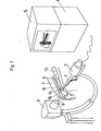
- FIG. 1 shows schematically the apparatus used for locking nailing, which consists of the x-ray source 3, the x-ray receiver 2 matched thereto and an image converter 4 with a monitor 5 connected to it.
- Located in the radiation field 9 of the X-ray apparatus is the patient's thigh 7 with the locking nail 6 already inserted into the medullary cavity of the femur 8, as well as the drill 1 with a sighting instrument 10 used to penetrate the outer corticalis.
- the relative position of the drill tip to the locking nail 6 and the alignment of the sighting instrument to the radiation field 9 can be tracked at any time on the monitor 5 of the image converter 4 and corrected if necessary.
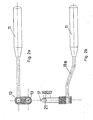
- the sighting instrument according to the invention shown in FIGS. 2a and b consists of a handle 11 to which a drill sleeve 12 is fastened, around which a crosshair sight 13 can be pivoted.
- the drill sleeve 12 essentially consists of a hollow cylinder having two teeth 21, which can receive a pin 16 made of plastic, at the tip of which a metal ball 17 is embedded.
- the actual visor 13 consists of two crosshairs which are rotated relative to one another in different planes or of two other suitable visor images, for example a circle and a point.
- the relative position of the intramedullary nail 6 with respect to the X-ray apparatus 2, 3 is aligned such that the locking holes 14, 15 are shown in a round manner on the monitor 5. This is the case when the axes of the locking holes 14, 15 are parallel to the radiation field 9.
- the hole to be locked should come to rest in the middle of the lower edge of the picture so that the crosshairs of the visor 13 come to rest in the center of the picture.
- the thigh 7 is then covered with a radiation protection mat which has an opening corresponding to the operating field.
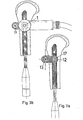
- the sighting instrument 10 can be inserted through the skin incision with the pin 16 inserted (FIG. 3a).
- the pin 16 simplifies the insertion of the sighting instrument through the soft parts, thanks to its spherical tip. After insertion, the tip of the pin 16 with the spherical reference body 17 is placed over the center of the locking hole. This work step is shown in FIG. 3a and shows the reference body 17 lying exactly in the center of the drill sleeve 12.
- the visor 13 should not be considered at this time.
- the sighting instrument is pressed firmly onto the femur 8.
- the teeth 21 of the drill sleeve 12 prevent the sighting instrument 10 from slipping off the femur 8.
- the sighting instrument 10 is not rotated around the drill sleeve 12, since the drill sleeve 12 serving as tissue protection rests on the femur 8 with the two teeth and not with a central tip.
- the pin 16 is removed and a 4.5 mm drill sleeve is inserted into the drill sleeve 12.
- the 4.5mm drill is now inserted into this 4.5mm drill sleeve, the tip of which lies exactly above the center of the locking hole.
- the drilling direction is set under the image intensifier. This is done, as shown in Figure 3b, by aligning the visor 13 perpendicular to the radiation field 9.
- the first cortex can be drilled out with the 4.5mm drill.
- the drilling direction can be checked continuously with the image intensifier and corrected if necessary by adjusting the sighting image.
- the locking hole is covered by the drilling machine in this operation step.
- the 4.5mm drill is removed from the 4.5mm drill sleeve and a 3.2mm push-in sleeve is inserted down to the opposite cortex.
- the image intensifier can now be swiveled away and the counter cortex can be drilled out with the 3.2 mm drill.
- the screw length is measured, a thread is cut in the counter cortex and the locking screw is inserted.
- radiation sources 3 are other than mentioned in the application example X-ray apparatus ver - reversible, such as ultrasound or specifically for Training company also ordinary, visible light.
- the tool 1 guided with the aiming device according to the invention can, in addition to the drill mentioned in the example, also consist of a saw, syringe or other surgical instrument.
- the aiming device according to the invention is preferably suitable for surgical tools and instruments used in orthopedics, arthroscopy, spinal surgery and puncture, the method used here can also be used for other non-surgical purposes.
- the axis 18 of the drill sleeve 12 lying in a common plane enclose an angle with the optical sighting line 20 in order to take into account the divergence of the radiation field 9 (FIG. 4a) .
- This embodiment which increases precision can be implemented either in a fixed or adjustable manner.
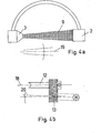
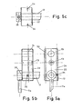
- FIGS. 5 a to c show the structure of this embodiment, which further simplifies the setting of the second locking screw, from three sides.
- the distance between the centers of the drill sleeve 23 and the drill sleeve 12 corresponds the exact distance between the centers of the two transverse bores 14, 15 of the locking nail 6.
- the visor 13 is arranged between the drill sleeve 23 and the drill sleeve 12 and is otherwise constructed in the same way as in the previously described embodiment of the invention.
- the block 22 in the radiation field 9 of the X-ray apparatus is made of a radiation-transmissive material, for example a plastic, and has two radiation-impermeable metal wires 24 running parallel to the plane of FIG. 5a.
- FIG. 6 shows the sighting instrument 10 after the first locking screw has been set in accordance with the surgical technique already described above.
- the associated monitor image typically shows an arrangement as shown in Figure 7a, i.e. the metal wires 24 embedded in the block 22 are not yet aligned parallel to the locking nail 6, but form an angle with it. Accordingly, the images of the drill sleeve 23 and the second locking hole 14 are not one above the other.
- the block 22, which is made of plastic, is essentially radiolucent, but in practice its contours can be recognized very weakly on the monitor image.
- Both the alignment and the fixing of the block 22 can be carried out by means of an ordinary hexagon screwdriver 28 which is inserted into the hexagon engagement of the locking screw 25, as shown in FIG. 6.
- both the drill sleeve 23 and the second Ver locking hole 14 is not circular, but is shown elliptically on the monitor. However, this does not matter for the alignment of the block 22, since only the parallelism of the reference metal wires 24 with the locking nail 6 is to be considered.
- a tissue protection sleeve is first inserted through the drill sleeve 23, into which the 4.5 mm drill sleeve can then be inserted.
- the rest of the procedure corresponds to that of setting the first locking screw.
- This time-saving and precision-increasing embodiment of the invention enables the already reduced x-ray dose to be reduced again to about half.
Landscapes
- Health & Medical Sciences (AREA)
- Surgery (AREA)
- Life Sciences & Earth Sciences (AREA)
- Engineering & Computer Science (AREA)
- Nuclear Medicine, Radiotherapy & Molecular Imaging (AREA)
- Medical Informatics (AREA)
- Public Health (AREA)
- Oral & Maxillofacial Surgery (AREA)
- Biomedical Technology (AREA)
- Heart & Thoracic Surgery (AREA)
- Dentistry (AREA)
- Molecular Biology (AREA)
- Animal Behavior & Ethology (AREA)
- General Health & Medical Sciences (AREA)
- Orthopedic Medicine & Surgery (AREA)
- Veterinary Medicine (AREA)
- Pathology (AREA)
- Radiology & Medical Imaging (AREA)
- Physics & Mathematics (AREA)
- Optics & Photonics (AREA)
- Mechanical Engineering (AREA)
- Apparatus For Radiation Diagnosis (AREA)
- Measurement Of Radiation (AREA)
Applications Claiming Priority (4)
| Application Number | Priority Date | Filing Date | Title |
|---|---|---|---|
| CH1932/85A CH664725A5 (de) | 1985-05-07 | 1985-05-07 | Zielvorrichtung mit einem in einem strahlenfeld zu betaetigendes werkzeug. |
| CH1932/85 | 1985-05-07 | ||
| CH4280/85 | 1985-10-03 | ||
| CH4280/85A CH671873A5 (fr) | 1985-10-03 | 1985-10-03 |
Publications (2)
| Publication Number | Publication Date |
|---|---|
| EP0201737A2 true EP0201737A2 (fr) | 1986-11-20 |
| EP0201737A3 EP0201737A3 (fr) | 1988-11-17 |
Family
ID=25689033
Family Applications (1)
| Application Number | Title | Priority Date | Filing Date |
|---|---|---|---|
| EP86105110A Withdrawn EP0201737A3 (fr) | 1985-05-07 | 1986-04-14 | Viseur |
Country Status (2)
| Country | Link |
|---|---|
| EP (1) | EP0201737A3 (fr) |
| BR (1) | BR8601918A (fr) |
Cited By (7)
| Publication number | Priority date | Publication date | Assignee | Title |
|---|---|---|---|---|
| EP0281763A3 (en) * | 1987-03-07 | 1989-08-09 | Howmedica Gmbh | Accessory instrument for positioning implantation holes of attachment nails |
| FR2634641A1 (fr) * | 1988-07-28 | 1990-02-02 | Michel Jean Pierre | Dispositif de visee pour le positionnement d'au moins un organe de fixation a travers un implant, du type clou centro-medullaire |
| US4917111A (en) * | 1987-10-15 | 1990-04-17 | Dietmar Pennig | Instrument for aiming and hole forming for implantation of locking nails of the like |
| FR2645428A1 (fr) * | 1989-04-11 | 1990-10-12 | Hardy Jean Marie | Fixateur pour intervention orthopedique |
| EP0354395A3 (fr) * | 1988-08-10 | 1990-12-05 | Ace Medical Company | Dispositif de visée pour broche intramédullaire |
| WO1991003982A1 (fr) * | 1989-09-13 | 1991-04-04 | Isis Innovation Limited | Appareillage et methode pour l'alignement d'un appareil de perçage utilise pour les interventions chirurgicales |
| EP0518071A1 (fr) * | 1991-06-13 | 1992-12-16 | Howmedica GmbH | Dispositif à faire des trous pour l'implantation des vis de verrouillage des clous intramedullaires |
Family Cites Families (5)
| Publication number | Priority date | Publication date | Assignee | Title |
|---|---|---|---|---|
| US3704707A (en) * | 1971-04-06 | 1972-12-05 | William X Halloran | Orthopedic drill guide apparatus |
| DE7805301U1 (de) * | 1978-02-22 | 1978-07-06 | Howmedica International, Inc. Zweigniederlassung Kiel, 2300 Kiel | Distales Zielgerät für die Verriegeliingsnagelung |
| SU848015A1 (ru) * | 1978-10-02 | 1981-07-23 | Казанский Ордена Трудового Красногознамени Государственный Медицинскийинститут Им. C.B.Курашова | Устройство дл прицельной пункции |
| DE3205404A1 (de) * | 1982-02-16 | 1983-09-15 | Patrick Dr.med. 3590 Bad Wildungen Kluger | Vorrichtung zum kontrollieren des richtungsgenauen fuehrens eines chirurgischen werkzeuges |
| DE8417428U1 (de) * | 1984-06-08 | 1984-09-13 | Howmedica International, Inc. Zweigniederlassung Kiel, 2300 Kiel | Zielgerät |
-
1986
- 1986-04-14 EP EP86105110A patent/EP0201737A3/fr not_active Withdrawn
- 1986-04-29 BR BR8601918A patent/BR8601918A/pt unknown
Cited By (9)
| Publication number | Priority date | Publication date | Assignee | Title |
|---|---|---|---|---|
| EP0281763A3 (en) * | 1987-03-07 | 1989-08-09 | Howmedica Gmbh | Accessory instrument for positioning implantation holes of attachment nails |
| US4917111A (en) * | 1987-10-15 | 1990-04-17 | Dietmar Pennig | Instrument for aiming and hole forming for implantation of locking nails of the like |
| FR2634641A1 (fr) * | 1988-07-28 | 1990-02-02 | Michel Jean Pierre | Dispositif de visee pour le positionnement d'au moins un organe de fixation a travers un implant, du type clou centro-medullaire |
| EP0358579A3 (fr) * | 1988-07-28 | 1990-07-18 | ICP FRANCE, Société Anonyme | Dispositif de visée pour le positionnement d'au moins un organe de fixation à travers un implant du type clou centromédullaire |
| EP0354395A3 (fr) * | 1988-08-10 | 1990-12-05 | Ace Medical Company | Dispositif de visée pour broche intramédullaire |
| FR2645428A1 (fr) * | 1989-04-11 | 1990-10-12 | Hardy Jean Marie | Fixateur pour intervention orthopedique |
| WO1990011727A1 (fr) * | 1989-04-11 | 1990-10-18 | Hardy Jean Marie | Fixateur pour intervention orthopedique |
| WO1991003982A1 (fr) * | 1989-09-13 | 1991-04-04 | Isis Innovation Limited | Appareillage et methode pour l'alignement d'un appareil de perçage utilise pour les interventions chirurgicales |
| EP0518071A1 (fr) * | 1991-06-13 | 1992-12-16 | Howmedica GmbH | Dispositif à faire des trous pour l'implantation des vis de verrouillage des clous intramedullaires |
Also Published As
| Publication number | Publication date |
|---|---|
| BR8601918A (pt) | 1986-12-30 |
| EP0201737A3 (fr) | 1988-11-17 |
Similar Documents
| Publication | Publication Date | Title |
|---|---|---|
| CH671873A5 (fr) | ||
| DE69837781T2 (de) | Zielgerät für Implantatvorrichtungen | |
| DE69716230T2 (de) | Orthopädische Vorrichtung, insbesondere zur chirurgischen Korrektur von Knockendeformationen | |
| DE69311594T2 (de) | Dreh- und winkelmässig einstellbare tibiale Schneidführung | |
| DE69912600T2 (de) | Stift zur provisorischen Befestigung einer Knochenplatte | |
| DE69200571T2 (de) | Vorrichtung zum Bohren von Löchern zur Implantation von Verriegelungsnägeln für Marknägel. | |
| DE3332642C2 (fr) | ||
| DE4412604C2 (de) | Vorrichtung zur ventralen Verschraubung von Dens-Frakturen mit Kompressionsschrauben | |
| DE60212852T2 (de) | Tibiale resektionsführung | |
| DE19713416B4 (de) | Führungsvorrichtung für ein Zwischenwirbelimplantat | |
| DE69127230T2 (de) | Führung mit intramedullärer Referenz, zur Resektion des Oberarmknochenkopfes | |
| EP0514662B1 (fr) | Instrument chirurgical pour positionner des éléments de fixation d'ostéosynthèse en particulier les vis osseuses | |
| DE102006026913B4 (de) | Operationsnavigationsnachverfolgungseinrichtung, -system und -verfahren | |
| DE60101162T2 (de) | Röntgenstrahlendurchlässiger führungsquide | |
| DE3925488A1 (de) | Fraeserausrichtfuehrung fuer osteoplastische chirurgie | |
| DE202005015975U1 (de) | Zielgerät | |
| DE29521736U1 (de) | Vorrichtung zur mechanischen Ausrichtung von Knochenschrauben in einem medullären Nagel | |
| DE3842645A1 (de) | Saegelehrensystem | |
| DE10301444A1 (de) | Intramedullärer Nagel, Einrichtung zum Einführen einer Schraube in diesen, und zugehöriges Verfahren | |
| DE29608071U1 (de) | Zielgerät zur Verriegelung der Fusspartie von Marknägeln | |
| EP1354562B1 (fr) | Système d' ostéosynthèse | |
| CH668692A5 (en) | Bone pin alignment instrument - has lockable head pivoting in all directions | |
| DE2919935A1 (de) | Vorrichtung zur fuehrung chirurgischer instrumente bei der umstellungsosteotomie am menschlichen hueftknochen | |
| EP1455662B1 (fr) | Dispositif de visee destine a une broche a fracture | |
| EP1099413A1 (fr) | Dispositif de visée pour le verrouillage distal d'un clou intramédullaire |
Legal Events
| Date | Code | Title | Description |
|---|---|---|---|
| PUAI | Public reference made under article 153(3) epc to a published international application that has entered the european phase |
Free format text: ORIGINAL CODE: 0009012 |
|
| AK | Designated contracting states |
Kind code of ref document: A2 Designated state(s): AT BE CH DE FR GB LI LU NL SE |
|
| RIN1 | Information on inventor provided before grant (corrected) |
Inventor name: FRIGG, ROBERT Inventor name: GYSIN, PAUL Inventor name: RITTER, GEBHARD Inventor name: PERREN, STEPHEN M., PROF. DR. MED. Inventor name: JENNY, URS |
|
| PUAL | Search report despatched |
Free format text: ORIGINAL CODE: 0009013 |
|
| AK | Designated contracting states |
Kind code of ref document: A3 Designated state(s): AT BE CH DE FR GB LI LU NL SE |
|
| 17P | Request for examination filed |
Effective date: 19881128 |
|
| 17Q | First examination report despatched |
Effective date: 19910820 |
|
| STAA | Information on the status of an ep patent application or granted ep patent |
Free format text: STATUS: THE APPLICATION IS DEEMED TO BE WITHDRAWN |
|
| 18D | Application deemed to be withdrawn |
Effective date: 19920922 |
|
| RIN1 | Information on inventor provided before grant (corrected) |
Inventor name: PERREN, STEPHEN M., PROF. DR. MED. Inventor name: RITTER, GEBHARD Inventor name: FRIGG, ROBERT Inventor name: JENNY, URS Inventor name: GYSIN, PAUL |