EP0201747A2 - Device for the parallel tensioning of printing plates in a printing machine - Google Patents
Device for the parallel tensioning of printing plates in a printing machine Download PDFInfo
- Publication number
- EP0201747A2 EP0201747A2 EP86105310A EP86105310A EP0201747A2 EP 0201747 A2 EP0201747 A2 EP 0201747A2 EP 86105310 A EP86105310 A EP 86105310A EP 86105310 A EP86105310 A EP 86105310A EP 0201747 A2 EP0201747 A2 EP 0201747A2
- Authority
- EP
- European Patent Office
- Prior art keywords
- tensioning
- clamping
- cylinder
- rail
- parallel
- Prior art date
- Legal status (The legal status is an assumption and is not a legal conclusion. Google has not performed a legal analysis and makes no representation as to the accuracy of the status listed.)
- Granted
Links
Images


Classifications
-
- B—PERFORMING OPERATIONS; TRANSPORTING
- B41—PRINTING; LINING MACHINES; TYPEWRITERS; STAMPS
- B41F—PRINTING MACHINES OR PRESSES
- B41F27/00—Devices for attaching printing elements or formes to supports
- B41F27/12—Devices for attaching printing elements or formes to supports for attaching flexible printing formes
- B41F27/1218—Devices for attaching printing elements or formes to supports for attaching flexible printing formes comprising printing plate tensioning devices
- B41F27/1225—Devices for attaching printing elements or formes to supports for attaching flexible printing formes comprising printing plate tensioning devices moving in the printing plate end substantially rectilinearly
- B41F27/1231—Devices for attaching printing elements or formes to supports for attaching flexible printing formes comprising printing plate tensioning devices moving in the printing plate end substantially rectilinearly by translatory motion substantially tangential to support surface
Definitions
- the invention relates to a device for parallel clamping of printing plates on the plate cylinder of printing machines according to the preamble of the first claim.
- Such a device is known from DE-AS 2 200 187.
- the disadvantage of this device is that the rear clamping rail is preferably arranged on the angular rail which can be displaced in the circumferential direction in the channel without means for lateral alignment, and from a relaxed position pushed forward against its channel wall with a quick-release mechanism with lever transmission in the cylinder circumferential direction only with an increased clamping path is tense.
- This rail can be moved in the released state of the pressure plate in the direction of the channel wall opposite the rear tensioning rail and can be moved by an eccentric lever transmission from the channel wall, so that the pressure plate is tensioned by an eccentric adjustment by the rear tensioning rail.
- any inequality in the released positions of the at least two tensioning screws distributed in the axial direction has an effect on the parallelism of the displacement of the rear tensioning rail to the channel wall when the plate is tensioned with the aid of the quick-action clamping mechanism. If the clamping screws in the rear clamping rail are not loosened exactly the same distance during the preparatory work for clamping a new pressure plate, then the rear clamping rail, which is not exactly guided sideways, is tilted during quick clamping and the rear pressure plate end is pulled obliquely, which means sensitive pressure plate means that it is stretched on one side and warps.
- the quick release mechanism known from DE-PS 2 754 080 does not have a series connection of a quick release device for pre-tensioning and tensioning device for the final tensioning. In this way, tilting of the rear tensioning rail can be avoided, because the rapid mounting of the pressure plate with a precisely defined tension takes place with a single step by parallel guidance of the rear tensioning rail in the cylinder channel by means of a symmetrical scissor arm linkage.
- this quick release device according to FIG.
- a quick clamping device for parallel clamping in which an angle rail for clamping printing plates of different printing lengths is arranged to be adjustable and lockable in several fixed positions parallel to the printing end, but only a limited clamping force due to an on the angle rail acting leaf spring can be generated during quick clamping.
- the device can be equipped with a split tensioning rail, but a section-wise correction of the printed image is not useful because a split rear tensioning rail is coupled again via the quick-action clamping device arranged symmetrically in the cylinder center plane. This means that the functions of quick clamping and final clamping cannot be separated, which means that undesired feedback on the clamping force is unavoidable.
- the invention is therefore based on the object of providing a device which makes it possible, with defined clamping forces, for a rear continuous or divided clamping rail to be parallel to its channel wall To carry out quick clamping without impairing their function and shape for the final clamping via the quick clamping mechanism and to arrange the quick clamping mechanism as space-saving as possible in the plate cylinder.
- the advantage of the device is that during quick clamping in connection with a rear split clamping rail, the pressure plate is clamped in parallel in order to achieve registration accuracy, but at the same time the known correction options of the printed image with a split clamping rail and the associated clamping screws are retained during final clamping.
- the space-saving arrangement of the quick-release mechanism with quick-release eccentric leads to a minimum channel angle and thus to a maximum cylinder circumference for clamping the pressure plate.
- the plate cylinder 1 of a printing press has means for fastening and tensioning printing plates in a cylinder channel 2. 1 and 2 as a front tensioning rail 3 divided over the length of the plate cylinder 1 and a correspondingly divided rear tensioning rail 4 and each arranged at the print start 5 and print end 6 of the cylinder channel 2.
- the divided clamping rails 3, 4 are arranged in a known manner in the cylinder channel 2 and are actuated by means of clamping screws 10, 11.
- the pressure plate front edge and the pressure plate rear edge are also clamped in a known manner by clamping devices 21, 22 (FIG. 2).
- the quick-action clamping device consists of a pressure bar 9 arranged along the cylinder channel 2 in a recess 7 of the plate cylinder 1 which runs behind the channel wall 8 and runs parallel to this recess 7.
- the pressure bar 9 is provided with an eccentric bolt arranged outside the cylinder center plane parallel to the tensioning screws 11 in the rear divided tensioning rail 4 12 along the Zylin derkanals 2 slidable.
- a parallel movement in the direction of the rear tensioning rail 4 can be carried out from the pressure bar 9 via specially designed recesses 13 in the pressure bar 9 and corresponding elevations on a counterpart 15, which lie opposite the tensioning screws 11 supported under the action of a compression spring 16.
- the elevations are preferably designed as a pressure roller 14.
- the depressions 13 in the pressure bar 9 are formed with a slope according to FIG. 3 which is larger and then smaller at the beginning of the tensioning path and runs into a radius R.
- the divided clamping rails 3, 4 are guided axially displaceably in the cylinder channel 2. 4, the setting angle ⁇ of the eccentric pin 12 is shown in a first position and in dashed lines in a second position, since the eccentric pin 12 carries out a compensating movement about the angle with the axial adjustment, while the pressure bar 9 remains in its position. With an appropriate design, the pressure bar 9 can also carry out the compensating movement.
- the divided tensioning rails 3, 4 are guided in sections in the circumferential direction and parallel or obliquely to the cylinder axis, also overall, in a known manner.
- FIG. 5 Another embodiment of the invention is shown in Fig. 5, which requires a slightly wider channel.
- 5 consists of a common drive unit 16, which is mounted in a cylinder-fixed support wall 17 arranged between the front and rear clamping rails 3, 4.
- a central adjustment 20 preferably a worm, chain or gear drive
- the individual tensioning screws 11 can be taken along by means of friction elements 18 via friction surfaces 19, the rear tensioning rail 4 being tensionable in parallel.
- the central adjustment 20 can also be designed to be disengaged or the like, so that no friction connection is required.
- the shape and function of the usual, previously described clamping device for final clamping remains unchanged in this embodiment as well, so that the above-mentioned correction options cannot be restricted by the quick-clamping mechanism.
Landscapes
- Supply, Installation And Extraction Of Printed Sheets Or Plates (AREA)
- Ink Jet (AREA)
- Printers Characterized By Their Purpose (AREA)
- Inking, Control Or Cleaning Of Printing Machines (AREA)
- Rotary Presses (AREA)
Abstract
Um mit definierten Spannkräften eine hintere durchgehende oder geteilte Spannschiene parallel zu ihrer Kanalwand beim Schnellspannen zu führen, ohne dabei über den Schnellspannmeahanismus deren Funktion und Form für das endgültige Spannen zu beeinträchtigen sowie dabei den Schnellspannmechanismus möglichst raumsparend im Plattenzylinder anzuordnen, besteht die Schnellspanneinrichtung aus einer längs des Zylinderkanals (2) in einer hinter der Ebene der Kanalwand (8) und parallel zu dieser verlaufenden Aussparung (7) des Plattenzylinders (1) angeordneten Druckleiste (9), die mit einem außerhalb der Zylindermittelebene parallel zu den Spannschrauben (11) in der hinteren Spannschiene (4) angeordneten Exzenterbolzen (12) längs des Zylinderkanals (2) verschiebbar ist, wobei über besonders gestaltete Vertiefungen (13) in der Druckleiste (9) und entsprechende Erhebungen an einem Gegenstück (15), welche jeweils den unter der Wirkung der Druckfeder (16) abgestützten Spannschrauben (11) gegenüberliegen, eine parallele Bewegung in Richtung der hinteren Spannschiene (4) ausführbar ist.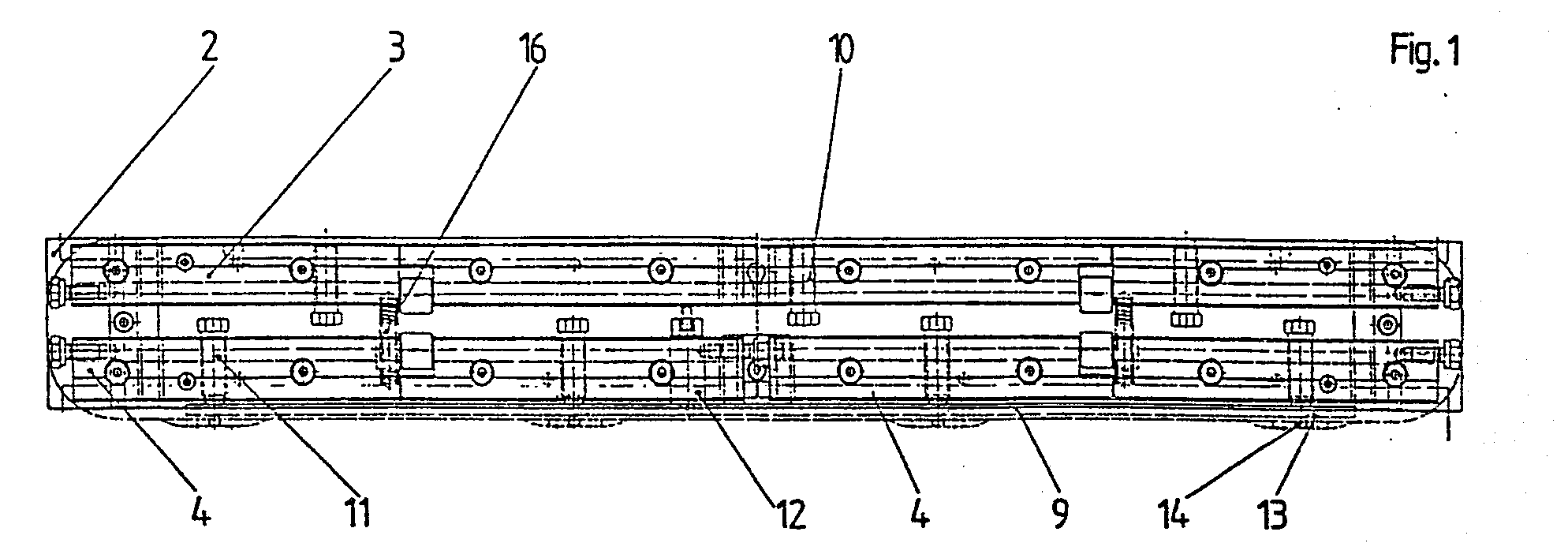
Description
Die Erfindung betrifft eine Vorrichtung zum parallelen Spannen von Druckplatten auf dem Plattenzylinder von Druckmaschinen entsprechend dem Oberbegriff des ersten Patentanspruches.The invention relates to a device for parallel clamping of printing plates on the plate cylinder of printing machines according to the preamble of the first claim.
Eine derartige Vorrichtung ist aus der DE-AS 2 200 187 bekannt. Von Nachteil ist bei dieser Vorrichtung, daß die hintere Spannschiene ohne Mittel zum seitlichen Ausrichten vorzugsweise auf einer im Kanal in Umfangsrichtung verschiebbaren Winkelschiene im Kanal angeordnet ist und aus einer gegen ihre Kanalwand vorgeschoben entspannten Stellung mit einem Schnellspannmechanismüs mit Hebelübersetzung in Zylinderumfangsrichtung nur mit einem vergrößerten Spannweg anspannbar ist. Diese Schiene kann im gelösten Zustand der Druckplatte in Richtung auf die der hinteren Spannschiene gegenüber stehende Kanalwand verschoben und durch einen Exzenter über eine Hebelübersetzung von der Kanalwand abgerückt werden, so daß durch eine Exzenterverstellung die Druckplatte durch die hintere Spannschiene angespannt wird. Da die hintere Spannschiene zwischen zwei Druckfedern angeordnet ist, wirkt sich jede Ungleichheit in den gelösten Stellungen der in Achsrichtung'verteilten wenigstens zwei Spannschrauben beim Anspannen der Platte mit Hilfe des Schnellspannmechanismus auf die Parallelität der Verschiebung der hinteren Spannschiene zur Kanalwand aus. Sind während der Vorbereitungsarbeiten zum Aufspannen einer neuen Druckplatte die Spannschrauben in der hinteren Spannschiene nicht exakt gleich weit gelöst, dann wird beim Schnellspannen die hintere, seitlich nicht exakt geführte Spannschiene verkantet und das hintere Druckplattenende wird schiefgezogen, was bei empfindlicher Druckplatte bedeutet, daß diese einseitig gedehnt wird und sich verzieht. Ein passergenaues Aufspannen der Platte ist dann nicht mehr möglich, da die plastische Verformung auch durch nachträgliche Korrektur mit Hilfe der Spannschrauben nicht mehr rückgängig gemacht werden kann. Wegen der bereits erwähnten Anordnung von zwei einander entgegenwirkenden Druckfedern, nämlich einer Druckfeder zwischen den Spannschienen und einer Druckfeder zwischen dem Exzenter und einer. Schwinghebel, ist auch keine definierte Spannkraft über die Druckplattenbreite bei nicht paralleler Stellung der beiden Spannschienen erreichbar. Das automatische Nachspannen über die Druckfeder zwischen den Spannschienen ist zwar theoretisch möglich, praktisch kann jedoch die erforderliche Spannkraft, insbesondere bei großen Formaten, derart nicht aufgebracht werden. Von Nachteil ist ferner, daß die Lagerung des Schwinghebels sehr stabil sein muß, wodurch ein großer Platzbedarf entsteht.Such a device is known from DE-AS 2 200 187. The disadvantage of this device is that the rear clamping rail is preferably arranged on the angular rail which can be displaced in the circumferential direction in the channel without means for lateral alignment, and from a relaxed position pushed forward against its channel wall with a quick-release mechanism with lever transmission in the cylinder circumferential direction only with an increased clamping path is tense. This rail can be moved in the released state of the pressure plate in the direction of the channel wall opposite the rear tensioning rail and can be moved by an eccentric lever transmission from the channel wall, so that the pressure plate is tensioned by an eccentric adjustment by the rear tensioning rail. Since the rear tensioning rail is arranged between two compression springs, any inequality in the released positions of the at least two tensioning screws distributed in the axial direction has an effect on the parallelism of the displacement of the rear tensioning rail to the channel wall when the plate is tensioned with the aid of the quick-action clamping mechanism. If the clamping screws in the rear clamping rail are not loosened exactly the same distance during the preparatory work for clamping a new pressure plate, then the rear clamping rail, which is not exactly guided sideways, is tilted during quick clamping and the rear pressure plate end is pulled obliquely, which means sensitive pressure plate means that it is stretched on one side and warps. It is then no longer possible to clamp the plate precisely, since the plastic deformation can no longer be undone by subsequent correction using the clamping screws. Because of the already mentioned arrangement of two opposing compression springs, namely a compression spring between the tensioning rails and a compression spring between the eccentric and one. Rocker arm, no defined clamping force can be reached across the pressure plate width when the two clamping rails are not in parallel. The automatic re-tensioning via the compression spring between the tensioning rails is theoretically possible, but in practice the required tensioning force, especially in the case of large formats, cannot be applied in this way. Another disadvantage is that the bearing of the rocker arm must be very stable, which creates a large amount of space.
Der aus der DE-PS 2 754 080 bekannte Schnellspannmechanismus weist keine Reihenschaltung aus einer Schnellspanneinrichtung zum Vorspannen und Spanneinrichtung für das endgültige Spannen auf. Dadurch kann zwar ein Verkanten der hinteren Spannschiene vermieden werden, weil das schnelle Aufspannen der Druckplatte mit genau definierter Spannung mit einem einzigen Ste11vorgang durch paralleles Führen der hinteren Spannschiene im Zylinderkanal mittels eines symmetrischen Scherenhebelgestänges erfolgt. Mit dieser Schnellspanneinrichtung ist jedoch gemäß Fig. 1 der Patentschrift kein seitliches Ausrichten und kein Ausrichten abschnittsweise in Umfangsrichtung, parallel oder schräg zur Zylinderachse mehr möglich, wodurch keine Korrektur der durch Spannungen im hygroskopischen Druckgut oder in den elastischen Gummitüchern verändertern Druckbilder und keine Abstimmung einzelner Druckplatten untereinander bei Mehrfarbenmaschinen mehr möglich ist. Gerade auf diese Korrekturen kommt es aber wesentlich an. Außerdem sind die Funktionen Schnellspannen und endgültiges Spannen nicht trennbar, um unerwünschte Rückkopplungen zu vermeiden.The quick release mechanism known from DE-PS 2 754 080 does not have a series connection of a quick release device for pre-tensioning and tensioning device for the final tensioning. In this way, tilting of the rear tensioning rail can be avoided, because the rapid mounting of the pressure plate with a precisely defined tension takes place with a single step by parallel guidance of the rear tensioning rail in the cylinder channel by means of a symmetrical scissor arm linkage. With this quick release device, however, according to FIG. 1 of the patent specification, there is no longer any lateral alignment and no alignment in sections in the circumferential direction, parallel or obliquely to the cylinder axis possible, which means that it is no longer possible to correct the print images changed by tension in the hygroscopic printed matter or in the elastic rubber blankets, and it is no longer possible to coordinate individual printing plates with one another in multi-color machines. It is precisely these corrections that are essential. In addition, the quick release and final release functions are inseparable to avoid unwanted feedback.
Aus der DE-PS 3 127 586 ist eine Schnellspanneinrichtung zum parallelen Spannen bekannt, bei der eine Winkelschiene zum Aufspannen von Druckplatten unterschiedlicher Drucklängenin mehreren festgelegten Stellungen parallel zum Druckende verstell- und arretierbar angeordnet ist, wobei aber nur eine begrenzte Spannkraft durch eine auf die Winkelschiene wirkende Blattfeder beim Schnellspannen erzeugt werden kann. Die Vorrichtung kann gemäß Fig. 2 zwar mit einer geteilten Spannschiene ausgerüstet werden, eine abschnittsweise Korrektur des Druckbildes ist aber deswegen nicht sinnvoll, weil über die in der Zylindermittelebene symmetrisch angeordnete Schnellspanneinrichtung eine geteilte hintere Spannschiene wieder gekoppelt ist. Dadurch sind die Funktionen Schnellspannen und endgültiges Spannen nicht trennbar, wodurch unerwünschte Rückkopplungen auf die Spannkraft unvermeidbar sind.From DE-PS 3 127 586 a quick clamping device for parallel clamping is known, in which an angle rail for clamping printing plates of different printing lengths is arranged to be adjustable and lockable in several fixed positions parallel to the printing end, but only a limited clamping force due to an on the angle rail acting leaf spring can be generated during quick clamping. According to FIG. 2, the device can be equipped with a split tensioning rail, but a section-wise correction of the printed image is not useful because a split rear tensioning rail is coupled again via the quick-action clamping device arranged symmetrically in the cylinder center plane. This means that the functions of quick clamping and final clamping cannot be separated, which means that undesired feedback on the clamping force is unavoidable.
Der Erfindung liegt deshalb die Aufgabe zugrunde, eine Vorrichtung zu schaffen, die es ermöglicht, mit definierten Spannkräften eine hintere durchgehende oder geteilte Spannschiene parallel zu ihrer Kanalwand beim Schnellspannen zu führen, ohne dabei über den Schnellspannmechanismus deren Funktion und Form für das endgültige Spannen zu beeinträchtigen sowie dabei den Schnellspannmechanismus möglichst raumsparend im Plattenzylinder anzuordnen.The invention is therefore based on the object of providing a device which makes it possible, with defined clamping forces, for a rear continuous or divided clamping rail to be parallel to its channel wall To carry out quick clamping without impairing their function and shape for the final clamping via the quick clamping mechanism and to arrange the quick clamping mechanism as space-saving as possible in the plate cylinder.
Gelöst wird diese Aufgabe durch eine Vorrichtung entsprechend dem Kennzeichen des ersten Patentanspruchs. Weiterbildungen der Erfindung ergeben sich aus den Unteransprüchen, der Beschreibung und der Zeichnung.This object is achieved by a device according to the characterizing part of the first claim. Further developments of the invention result from the subclaims, the description and the drawing.
Der Vorteil der Vorrichtung besteht darin, daß beim Schnellspannen in Verbindung mit einer hinteren geteilten Spannschiene die Druckplatte parallel gespannt wird, um Passergenauigkeit zu erreichen, zugleich aber beim endgültigen Spannen die bekannten Korrekturmöglichkeiten des Druckbildes mit einer geteilten Spannschiene und den zugehörigen Spannschrauben erhalten bleiben. Außerdem führt die raumsparende Anordnung des Schnellspannmechanismus mit Schnellspannexzenter zu einem minimalen Kanalwinkel und damit zu maximalem Zylinderumfang zum Aufspannen der Druckplatte.The advantage of the device is that during quick clamping in connection with a rear split clamping rail, the pressure plate is clamped in parallel in order to achieve registration accuracy, but at the same time the known correction options of the printed image with a split clamping rail and the associated clamping screws are retained during final clamping. In addition, the space-saving arrangement of the quick-release mechanism with quick-release eccentric leads to a minimum channel angle and thus to a maximum cylinder circumference for clamping the pressure plate.
Die Erfindung wird nachstehend an einem Ausführungsbeispiel näher erläutert. In der zugehörigen Zeichnung zeigt
- Fig. 1 eine Draufsicht auf die den Kanal zeigenden Seite eines Plattenzylinders,
- Fig. 2 eine im Zylinderkanal des Plattenzylinders angeordnete Plattenspannvorrichtung im Schnitt im vergrößerten Maßstab,
- Fig. 3 eine Einzelheit der Plattenspannvorrichtung im stark vergrößerten Maßstab,
- Fig. 4 den Stellwinkel des Exzenterbolzens in zwei Positionen der Axialverstellung im stark vergrößerten Maßstab,
- Fig. 5 eine andere Ausführungsform der Erfindung.
- 1 is a plan view of the side of a plate cylinder showing the channel,
- 2 shows a plate clamping device arranged in the cylinder channel of the plate cylinder in section on an enlarged scale,
- 3 shows a detail of the plate clamping device on a greatly enlarged scale,
- 4 the adjusting angle of the eccentric pin in two positions of the axial adjustment on a greatly enlarged scale,
- Fig. 5 shows another embodiment of the invention.
Der Plattenzylinder 1 einer Druckmaschine weist in einem Zylinderkanal 2 Mittel zum Befestigen und Spannen von Druckplatten auf. Diese Befestigungsmittel sind gemäß Fig. 1 und 2 als vordere über die Länge des Plattenzylinders 1 geteilte Spannschiene 3 und eine entsprechend geteilte hintere Spannschiene 4 ausgebildet und jeweils am Druckanfang 5 und Druckende 6 des Zylinderkanals 2 angeordnet. Die geteilten Spannschienen 3, 4 sind in bekannter Weise im Zylinderkanal 2 angeordnet und werden mittels Spannschrauben 10, 11 betätigt. In den Spannschienen 3, 4 werden ebenfalls in bekannter Weise die Druckplattenvorderkante sowie die Druckplattenhinterkante durch Klemmeinrichtungen 21, 22 geklemmt (Fig. 2). Die Schnellspanneinrichtung besteht aus einer längs des Zylinderkanals 2 in einer hinter der Kanalwand 8 parallel zu dieser verlaufenden Aussparung 7 des Plattenzylinders 1 angeordneten Druckleiste 9. Die Druckleiste 9 ist mit einem außerhalb der Zylindermittelebene parallel zu den Spannschrauben 11 in der hinteren geteilten Spannschiene 4 angeordneten Exzenterbolzen 12 längs des Zylinderkanals 2 verschiebbar. Von der Druckleiste 9 ist über besonders gestaltete Vertiefungen 13 in der Druckleiste 9 und entsprechende Erhebungen an einem Gegenstück 15, welche den unter der Wirkung einer Druckfeder 16 abgestützten Spannschrauben 11 gegenüber liegen, eine parallele Bewegung in Richtung der hinteren Spannschiene 4 ausführbar. Die Erhebungen sind vorzugsweise als Druckrolle 14 ausgebildet. Die Vertiefungen 13 in der Druckleiste 9 sind mit einer am Anfang des Spannweges größeren und dann kleineren, in einen Radius R auslaufenden Steigung gemäß Fig. 3 ausgebildet. Die geteilten Spannschienen 3, 4 sind im Zylinderkanal 2 axial verschiebbar geführt. Dabei ist in Fig. 4 der Stellwinkel α des Exzenterbolzens 12 in einer ersten Position und gestrichelt in einer zweiten Position gezeigt, da der Exzenterbolzen 12 eine Ausgleichsbewegung um den Winkele mit der axialen Verstellung ausführt, während die Druckleiste 9 in ihrer Position verbleibt. Bei entsprechender Auslegungkann die Druckleiste 9 auch die Ausgleichsbewegung mit vollziehen. Außerdem sind die geteilten Spannschienen 3, 4 abschnittsweise in Umfangsrichtung sowie parallel oder schräg.zur Zylinderachse, auch insgesamt, in bekannter Weise verschiebbar geführt. Dadurch ist mit der erfindungsgemäßen Vorrichtung eine parallele Bewegung in Richtung der hinteren geteilten Spannschiene 4 beim Schnellspannen möglich, ohne daß durch den Schnellspannmechanismus die bekannten Korrekturmöglichkeiten in Umfangsrichtung und/oder in axialer Richtung eingeschränkt werden. Das führt zu den vorn beschriebenen Vorteilen in Verbindung mit einer raumsparenden Anordnung eines Schnellspannmechanismus mit Exzenterverstellung.The
Eine andere Ausführungsform der Erfindung ist in Fig. 5 gezeigt, bei der ein etwas breiterer Kanal erforderlich ist. Zur Vereinfachung sind für beide Ausführungsformen gleiche Bezugszeichen verwendet worden. Die Schnellspanneinrichtung gemäß Fig. 5 besteht aus einer gemeinsamen Antriebseinheit 16, die in einer zwischen vorderen und hinteren Spannschiene 3, 4 angeordneten zylinderfesten Stützwand 17 gelagert ist. Durch Betätigung einer Zentralverstellung 20, vorzugsweise einem Schnecken-, Ketten- oder Zahnradtrieb, sind mittels Reibelementen 18 über Reibflächen 19 die einzelnen Spannschrauben 11 mitnehmbar, wobei die hintere Spannschiene 4 parallel spannbar ist. Gemäß einer Weiterbildung kann die Zentralverstellung 20 auch ausrastbar oder dgl. trennbar ausgeführt sein, so daß keine Reibverbindung erforderlich ist. Die übliche, zuvor beschriebene Spannvorrichtung zum endgültigen Spannen bleibt in ihrer Form und Funktion auch bei dieser Ausführungsform unverändert, so daß die genannten Korrekturmöglichkeiten vom Schnellspannmechanismus nicht eingeschränkt werden können.Another embodiment of the invention is shown in Fig. 5, which requires a slightly wider channel. For simplification, the same reference numerals have been used for both embodiments. 5 consists of a
- 1 Plattenzylinder1 plate cylinder
- 2 Zylinderkanal2 cylinder channel
- 3 vordere geteilte Spannschiene3 front split clamping rails
- 4 hintere geteilte Spannschiene4 rear split clamping rails
- 5 Druckanfang5 Start of printing
- 6 Druckende6 end of print
- 7 Aussparung7 recess
- 8 Kanalwand8 channel wall
- 9 Druckleiste9 print bar
- 10 Spannschraube10 clamping screw
- 11 Spannschraube11 clamping screw
- 12 Exzenterbolzen12 eccentric bolts
- 13 Vertiefungen13 wells
- 14 Druckrolle14 pressure roller
- 15 Gegenstück15 counterpart
- 16 gemeinsame Antriebseinheit16 common drive unit
- 17 zylinderfeste Stützwand17 cylinder-fixed retaining wall
- 18 Reibelement18 friction element
- 19 Reibfläche19 friction surface
- 20 Zentralverstellung20 central adjustment
- 21 Klemmeinrichtung21 clamping device
- 22 Klemmeinrichtung22 clamping device
Claims (6)
dadurch gekennzeichnet,
daß die Schnellspanneinrichtung aus einer längs des Zylinderkanals (2) in einer hinter der Ebene der Kanalwand (8) und parallel zu dieser verlaufenden Aussparung (7) des Plattenzylinders (1) angeordneten Druckleiste (9) besteht, die mit einem außerhalb der Zylindermittelebene parallel zu den Spannschrauben (11) in der hinteren Spannschiene (4) angeordneten Exzenterbolzen (12) längs des Zylinderkanals (2) verschiebbar ist, wobei über besonders gestaltete Vertiefungen (13) in der Druckleiste (9) und entsprechende Erhebungen an einem Gegenstück (15), welche jeweils den unter der Wirkung der Druckfeder (16) abgestützten Spannschrauben (11) gegenüberliegenden, eine parallele Bewegung in Richtung der hinteren Spannschiene (4) ausführbar ist.1.) Device for parallel clamping of printing plates on the plate cylinder of printing presses with a front and a rear clamping rail in the channel of the plate cylinder, on which the pressure plate ends can be clamped and which can be moved essentially in the circumferential direction of the plate cylinder by clamping screws lying apart in the axial direction, the Tensioning screws of the front tensioning rail are supported directly on the channel wall opposite them and the rear tensioning rail can be tensioned from a relaxed position advanced against its channel wall with a quick-release device that has a series connection of a quick-release mechanism with quick-release eccentric for pre-tensioning and tensioning screws for final tensioning, as well as between the front tensioning rail and the rear tensioning rail are arranged for automatic return of the tensioning rails to their starting positions,
characterized,
that the quick release device from a along the cylinder channel (2) in a behind the plane of the channel wall (8) and parallel to this There is a recess (7) in the plate cylinder (1) arranged pressure bar (9) which can be moved along the cylinder channel (2) with an eccentric bolt (12) arranged outside the central cylinder plane parallel to the clamping screws (11) in the rear clamping rail (4), parallel movement in the direction of the rear tensioning rail via specially designed depressions (13) in the pressure bar (9) and corresponding elevations on a counterpart (15), each of which opposes the tensioning screws (11) supported under the action of the pressure spring (16) (4) is executable.
dadurch gekennzeichnet, daß die Erhebungen vorzugsweise als Druckrollen (14) ausgebildet sind.2.) Device according to claim 1,
characterized in that the elevations are preferably designed as pressure rollers (14).
dadurch gekennzeichnet, daß die Vertiefungen (13) in der Druckleiste (9) mit einer am Anfang des Spannweges größeren und dann kleineren, in einen Radius (R) auslaufenden Steigung (Fig. 3) ausgebildet sind.3.) Device according to claim 1 and 2,
characterized in that the depressions (13) in the pressure bar (9) are formed with a larger (and then smaller) slope (Fig. 3) at the beginning of the tensioning path and ending in a radius (R).
dadurch gekennzeichnet, daß die Spannschienen (3, 4) im Zylinderkanal (2) axial verschiebbar geführt sind, wobei vom Exzenterbolzen (12) eine Ausgleichsbewegung (Fig. 4, gestrichelte Position) ausführbar ist, während je nach Lagerungdie Druckleiste (9) entweder in ihrer Position verbleibt oder eine Ausgleichsbewegung ausführt und die Spannschienen (3, 4) außerdem abschnittsweise oder insgesamt in Umfangsrichtung parallel oder schräg zur Zylinderachse verschiebbar geführt sind.4.) Device according to claim 1 to 3,
characterized in that the tensioning rails (3, 4) are axially displaceably guided in the cylinder channel (2), a compensating movement (FIG. 4, dashed position) being executable by the eccentric bolt (12), while, depending on the mounting, the pressure bar (9) either in remains in position or performs a compensating movement and the tensioning rails (3, 4) also are guided in sections or as a whole in the circumferential direction parallel or obliquely to the cylinder axis.
dadurch gekennzeichnet, daß die Schnellspanneinrichtung aus einer gemeinsamen Antriebseinheit (16), vorzugsweise einem Schnecken-, Ketten- oder Zahnradtrieb besteht, die in einer zwischen vorderen und hinteren Spannschiene (3, 4) angeordneten zylinderfesten Stützwand (17) gelagert ist und mittels Reibelementen (18) über Reibflächen (19) die einzelnen Spannschrauben (11) durch die Betätigung einer Zentralverstellung (20) mitnehmbar sind, wobei die hintere Spannschiene (4) parallel spannbar ist.5.) Device with the features of the preamble according to claim 1,
characterized in that the quick release device consists of a common drive unit (16), preferably a worm, chain or gear drive, which is mounted in a cylinder-fixed support wall (17) arranged between the front and rear tensioning rails (3, 4) and by means of friction elements ( 18) via friction surfaces (19) the individual tensioning screws (11) can be taken away by actuating a central adjustment (20), the rear tensioning rail (4) being tensionable in parallel.
dadurch gekennzeichnet, daß zur Vermeidung einer Reibverbindung die einzelnen Spannschrauben (11) unmittelbar durch die Betätigung einer Zentralverstellung (20) mitnehmbar sind, welche ausrastbar oder dgl. trennbar ausgeführt ist.6.) Device according to claim 5,
characterized in that, in order to avoid a frictional connection, the individual tensioning screws (11) can be taken directly by actuating a central adjustment (20) which can be disengaged or the like.
Priority Applications (1)
| Application Number | Priority Date | Filing Date | Title |
|---|---|---|---|
| AT86105310T ATE49925T1 (en) | 1985-05-09 | 1986-04-17 | DEVICE FOR PARALLEL CLAMPING OF PRINTING PLATES ON THE PLATE CYLINDER OF PRINTING MACHINES. |
Applications Claiming Priority (2)
| Application Number | Priority Date | Filing Date | Title |
|---|---|---|---|
| DE19853516682 DE3516682A1 (en) | 1985-05-09 | 1985-05-09 | DEVICE FOR PARALLELLY TENSIONING PRINTING PLATES ON THE PLATE CYLINDER OF PRINTING MACHINES |
| DE3516682 | 1985-05-09 |
Publications (3)
| Publication Number | Publication Date |
|---|---|
| EP0201747A2 true EP0201747A2 (en) | 1986-11-20 |
| EP0201747A3 EP0201747A3 (en) | 1987-12-23 |
| EP0201747B1 EP0201747B1 (en) | 1990-01-31 |
Family
ID=6270245
Family Applications (1)
| Application Number | Title | Priority Date | Filing Date |
|---|---|---|---|
| EP86105310A Expired - Lifetime EP0201747B1 (en) | 1985-05-09 | 1986-04-17 | Device for the parallel tensioning of printing plates in a printing machine |
Country Status (6)
| Country | Link |
|---|---|
| US (1) | US4688484A (en) |
| EP (1) | EP0201747B1 (en) |
| JP (1) | JPH0825267B2 (en) |
| AT (1) | ATE49925T1 (en) |
| BR (1) | BR8602277A (en) |
| DE (1) | DE3516682A1 (en) |
Cited By (2)
| Publication number | Priority date | Publication date | Assignee | Title |
|---|---|---|---|---|
| EP0534214A1 (en) * | 1991-09-20 | 1993-03-31 | Heidelberger Druckmaschinen Aktiengesellschaft | Method and device for correcting trapezoidal register deviations |
| US5398609A (en) * | 1991-08-16 | 1995-03-21 | Koenig & Bauer Aktiengesellschaft | Device for tensioning and adjusting flexible printing plates on plate cylinders of rotary presses |
Families Citing this family (17)
| Publication number | Priority date | Publication date | Assignee | Title |
|---|---|---|---|---|
| US5182994A (en) * | 1989-08-04 | 1993-02-02 | Komori Corporation | Plate lockup apparatus for sheet-fed press |
| DE69023829T2 (en) * | 1989-08-04 | 1996-07-04 | Komori Printing Mach | Printing plate attachment for a sheet printing machine. |
| DE3936458C1 (en) * | 1989-11-02 | 1991-04-11 | Man Roland Druckmaschinen Ag, 6050 Offenbach, De | |
| DE3936459C1 (en) * | 1989-11-02 | 1991-04-18 | Man Roland Druckmaschinen Ag, 6050 Offenbach, De | |
| US5199352A (en) * | 1990-02-24 | 1993-04-06 | Komori Corporation | Plate lock-up device for printing press |
| DE4100408C1 (en) * | 1991-01-09 | 1992-05-14 | Man Miller Druckmaschinen Gmbh, 6222 Geisenheim, De | |
| DE4111636C1 (en) * | 1991-04-10 | 1992-07-30 | Man Roland Druckmaschinen Ag, 6050 Offenbach, De | |
| DE4214206C2 (en) * | 1992-04-30 | 1995-06-29 | Roland Man Druckmasch | Device for actuating a clamping rail relative to the clamping rail of the plate cylinder of a rotary printing press, in particular sheet-fed offset printing press |
| DE9207780U1 (en) * | 1992-06-10 | 1992-10-22 | MAN Roland Druckmaschinen AG, 6050 Offenbach | Device for operating a clamping rail opposite the tensioning rail of the plate cylinder of a printing press |
| US5322014A (en) * | 1992-08-25 | 1994-06-21 | Keller James J | Printing plate register system, device, and method |
| DE4326248C2 (en) * | 1992-12-24 | 1996-05-15 | Koenig & Bauer Albert Ag | Clamping device in a rotary printing machine |
| GR960100252A (en) * | 1996-07-17 | 1998-03-31 | Metal plate rods for offset printing machines for the rapid and accurate positioning of the metal plate onto the cylinder (furnace). | |
| US5922406A (en) * | 1996-10-11 | 1999-07-13 | Ludford, Iii; Robert E. | Coating method and apparatus |
| US6026746A (en) * | 1998-09-22 | 2000-02-22 | E. R. Smith Associates, Inc. | Lock-up assembly for plate cylinders of rotary presses |
| DE19956833B4 (en) * | 1999-11-12 | 2009-04-23 | Dr. Johannes Heidenhain Gmbh | angle measurement |
| DE102008023728A1 (en) * | 2008-05-15 | 2009-11-19 | Koenig & Bauer Aktiengesellschaft | Printing plate end position adjusting device for use during operation of printing machine, has tensioning unit transferring partial elements into tensioning position, and another tensioning unit transferring partial elements beyond position |
| CN109773067A (en) * | 2019-02-28 | 2019-05-21 | 苏州欧方电子科技有限公司 | Precision Steel Sheet Tensioner |
Family Cites Families (17)
| Publication number | Priority date | Publication date | Assignee | Title |
|---|---|---|---|---|
| DE1922749C3 (en) * | 1969-05-03 | 1974-05-16 | Roland Offsetmaschf | Device for fastening a printing plate on the forme cylinder of a printing machine |
| DE2200187C3 (en) * | 1971-01-28 | 1981-05-07 | VEB Kombinat Polygraph "Werner Lamberz" Leipzig, DDR 7050 Leipzig | Device for precisely positioned quick clamping of flexible printing plates |
| US3752075A (en) * | 1971-04-26 | 1973-08-14 | Wood Industries Inc | Flexible printing plate clamping device |
| US3795193A (en) * | 1971-04-30 | 1974-03-05 | Polygraph Leipzig Kom Veb | Device for rapidly and precisely mounting flexible printing plates |
| DE2225016C3 (en) * | 1972-05-23 | 1976-01-29 | Koenig & Bauer Ag | DEVICE FOR CLAMPING FLEXIBLE PRINTING PLATES ON FORMING CYLINDERS OF ROTARY PRINTING MACHINES |
| US3908546A (en) * | 1972-10-16 | 1975-09-30 | Motter Printing Press Co | Plate clamping mechanism for printing cylinder |
| AT324361B (en) * | 1973-03-01 | 1975-08-25 | Heidelberger Druckmasch Ag | DEVICE FOR CLAMPING UP FLEXIBLE PRESSURE PLATES |
| JPS5338413Y2 (en) * | 1973-09-18 | 1978-09-18 | ||
| DE2431133A1 (en) * | 1974-06-28 | 1976-01-15 | Roland Offsetmaschf | PRINT PLATE CLAMPING DEVICE |
| DE2501511C2 (en) * | 1975-01-16 | 1983-06-01 | M.A.N. Maschinenfabrik Augsburg-Nürnberg AG, 8900 Augsburg | Device for attaching a flexible printing plate to the plate cylinder of a rotary printing press |
| DE2754080C3 (en) * | 1977-12-05 | 1982-01-07 | Registersystem für die Drucktechnik GmbH, 8000 München | Device for clamping printing plates in register on the plate cylinder of printing machines |
| DE3127586C1 (en) * | 1981-07-13 | 1982-12-09 | M.A.N.- Roland Druckmaschinen AG, 6050 Offenbach | Clamping device for clamping printing plates on the plate cylinder of a printing machine |
| JPS5967055A (en) * | 1982-10-09 | 1984-04-16 | Komori Printing Mach Co Ltd | Plate backup device for sheet-fed rotary press |
| DE3315488A1 (en) * | 1983-04-28 | 1984-10-31 | Albert-Frankenthal Ag, 6710 Frankenthal | DEVICE FOR TENSIONING PRINTING PLATES |
| CH653616A5 (en) * | 1983-07-26 | 1986-01-15 | De La Rue Giori Sa | METHOD FOR FIXING AND ADJUSTING A PRINTING PLATE ON A PLATE-HOLDING CYLINDER AND DEVICE FOR IMPLEMENTING SAME. |
| JPS6032033U (en) * | 1983-08-10 | 1985-03-05 | 三菱重工業株式会社 | Printing press clamping device |
| EP0142874B1 (en) * | 1983-11-14 | 1988-04-27 | De La Rue Giori S.A. | Plate cylinder with a device for affixing gravure printing plates for a web-printing machine |
-
1985
- 1985-05-09 DE DE19853516682 patent/DE3516682A1/en active Granted
-
1986
- 1986-04-17 EP EP86105310A patent/EP0201747B1/en not_active Expired - Lifetime
- 1986-04-17 AT AT86105310T patent/ATE49925T1/en not_active IP Right Cessation
- 1986-05-02 US US06/859,043 patent/US4688484A/en not_active Expired - Fee Related
- 1986-05-09 BR BR8602277A patent/BR8602277A/en not_active IP Right Cessation
- 1986-05-09 JP JP61105060A patent/JPH0825267B2/en not_active Expired - Fee Related
Cited By (2)
| Publication number | Priority date | Publication date | Assignee | Title |
|---|---|---|---|---|
| US5398609A (en) * | 1991-08-16 | 1995-03-21 | Koenig & Bauer Aktiengesellschaft | Device for tensioning and adjusting flexible printing plates on plate cylinders of rotary presses |
| EP0534214A1 (en) * | 1991-09-20 | 1993-03-31 | Heidelberger Druckmaschinen Aktiengesellschaft | Method and device for correcting trapezoidal register deviations |
Also Published As
| Publication number | Publication date |
|---|---|
| US4688484A (en) | 1987-08-25 |
| EP0201747A3 (en) | 1987-12-23 |
| DE3516682A1 (en) | 1986-11-13 |
| ATE49925T1 (en) | 1990-02-15 |
| BR8602277A (en) | 1987-01-21 |
| JPS6211648A (en) | 1987-01-20 |
| DE3516682C2 (en) | 1988-06-01 |
| EP0201747B1 (en) | 1990-01-31 |
| JPH0825267B2 (en) | 1996-03-13 |
Similar Documents
| Publication | Publication Date | Title |
|---|---|---|
| EP0201747A2 (en) | Device for the parallel tensioning of printing plates in a printing machine | |
| EP0238804B1 (en) | Device for attaching flexible printing forms to the plate cylinder of a rotary printing machine | |
| DE2744371B2 (en) | Device for fastening and tensioning flexible pressure plates | |
| DE3409479C2 (en) | ||
| EP1481803A1 (en) | Plate cylinder for a printing press | |
| DE3127586C1 (en) | Clamping device for clamping printing plates on the plate cylinder of a printing machine | |
| DE4444062A1 (en) | Adjustable alignment device for printing plates | |
| DE3936459C1 (en) | ||
| DE69105036T2 (en) | Clamping device for a printing plate in a printing press. | |
| EP0429808B1 (en) | Device for precisely registering and tensioning a printing plate upon an impression cylinder | |
| DE19619941A1 (en) | Plate clamping device to reduce the pressure-free area | |
| DE3115141C2 (en) | Device for diagonally adjusting a cylinder of a printing machine, preferably the plate cylinder of a sheet-fed rotary offset printing machine | |
| DE8513718U1 (en) | Device for parallel clamping of printing plates on the plate cylinder of printing machines | |
| DE10013804B4 (en) | Method and device for mounting a cylinder lift on a printing machine cylinder | |
| DE2754080C3 (en) | Device for clamping printing plates in register on the plate cylinder of printing machines | |
| DE4314436C2 (en) | Clamping rail for the plate cylinder of a printing press, in particular sheet-fed offset printing press | |
| DE4140022C2 (en) | Device for clamping a printing plate on a plate cylinder of a printing machine | |
| DE4134310C2 (en) | Device for quick clamping of printing plates | |
| DE4240462C2 (en) | Device for the precise registration of printing plates on the plate cylinder of printing machines | |
| DE4134364A1 (en) | Device for rapid fixing of flexible printing plate in accurate position - has counterpoised spring-supported rear fixing rail and front fixing rail jointly pivotable around first rotary point in cylinder channel fitted to pivot frame | |
| DE1227480B (en) | Device for clamping flexible printing plates on the forme cylinder of a printing machine | |
| DE2425011A1 (en) | MULTIPLE ROLLER PRINTING UNIT, IN PARTICULAR FLEXO PRINTING UNIT | |
| DE8111340U1 (en) | DEVICE FOR DIAGONALLY ADJUSTING A CYLINDER OF A PRINTING MACHINE, PREFERABLY THE PLATE CYLINDER OF AN ARC ROTATION OFFSET PRINTING MACHINE | |
| DE29616278U1 (en) | Clamping device for printing plates | |
| DE1256656B (en) | Fixing device for stereotype plates on the forme cylinder of rotary printing machines |
Legal Events
| Date | Code | Title | Description |
|---|---|---|---|
| PUAI | Public reference made under article 153(3) epc to a published international application that has entered the european phase |
Free format text: ORIGINAL CODE: 0009012 |
|
| AK | Designated contracting states |
Kind code of ref document: A2 Designated state(s): AT CH FR GB IT LI NL SE |
|
| 17P | Request for examination filed |
Effective date: 19870827 |
|
| PUAL | Search report despatched |
Free format text: ORIGINAL CODE: 0009013 |
|
| AK | Designated contracting states |
Kind code of ref document: A3 Designated state(s): AT CH FR GB IT LI NL SE |
|
| 17Q | First examination report despatched |
Effective date: 19880923 |
|
| ITF | It: translation for a ep patent filed | ||
| GRAA | (expected) grant |
Free format text: ORIGINAL CODE: 0009210 |
|
| AK | Designated contracting states |
Kind code of ref document: B1 Designated state(s): AT CH FR GB IT LI NL SE |
|
| REF | Corresponds to: |
Ref document number: 49925 Country of ref document: AT Date of ref document: 19900215 Kind code of ref document: T |
|
| ET | Fr: translation filed | ||
| GBT | Gb: translation of ep patent filed (gb section 77(6)(a)/1977) | ||
| PLBE | No opposition filed within time limit |
Free format text: ORIGINAL CODE: 0009261 |
|
| STAA | Information on the status of an ep patent application or granted ep patent |
Free format text: STATUS: NO OPPOSITION FILED WITHIN TIME LIMIT |
|
| 26N | No opposition filed | ||
| ITTA | It: last paid annual fee | ||
| EAL | Se: european patent in force in sweden |
Ref document number: 86105310.6 |
|
| PGFP | Annual fee paid to national office [announced via postgrant information from national office to epo] |
Ref country code: CH Payment date: 19950316 Year of fee payment: 10 |
|
| PGFP | Annual fee paid to national office [announced via postgrant information from national office to epo] |
Ref country code: FR Payment date: 19950320 Year of fee payment: 10 |
|
| PGFP | Annual fee paid to national office [announced via postgrant information from national office to epo] |
Ref country code: AT Payment date: 19950321 Year of fee payment: 10 |
|
| PGFP | Annual fee paid to national office [announced via postgrant information from national office to epo] |
Ref country code: NL Payment date: 19950430 Year of fee payment: 10 |
|
| PGFP | Annual fee paid to national office [announced via postgrant information from national office to epo] |
Ref country code: GB Payment date: 19960313 Year of fee payment: 11 |
|
| PGFP | Annual fee paid to national office [announced via postgrant information from national office to epo] |
Ref country code: SE Payment date: 19960321 Year of fee payment: 11 |
|
| PG25 | Lapsed in a contracting state [announced via postgrant information from national office to epo] |
Ref country code: AT Effective date: 19960417 |
|
| PG25 | Lapsed in a contracting state [announced via postgrant information from national office to epo] |
Ref country code: LI Effective date: 19960430 Ref country code: CH Effective date: 19960430 |
|
| PG25 | Lapsed in a contracting state [announced via postgrant information from national office to epo] |
Ref country code: NL Effective date: 19961101 |
|
| REG | Reference to a national code |
Ref country code: CH Ref legal event code: PL |
|
| PG25 | Lapsed in a contracting state [announced via postgrant information from national office to epo] |
Ref country code: FR Effective date: 19961227 |
|
| NLV4 | Nl: lapsed or anulled due to non-payment of the annual fee |
Effective date: 19961101 |
|
| REG | Reference to a national code |
Ref country code: FR Ref legal event code: ST |
|
| PG25 | Lapsed in a contracting state [announced via postgrant information from national office to epo] |
Ref country code: GB Effective date: 19970417 |
|
| PG25 | Lapsed in a contracting state [announced via postgrant information from national office to epo] |
Ref country code: SE Effective date: 19970418 |
|
| GBPC | Gb: european patent ceased through non-payment of renewal fee |
Effective date: 19970417 |
|
| EUG | Se: european patent has lapsed |
Ref document number: 86105310.6 |
|
| PG25 | Lapsed in a contracting state [announced via postgrant information from national office to epo] |
Ref country code: IT Free format text: LAPSE BECAUSE OF NON-PAYMENT OF DUE FEES;WARNING: LAPSES OF ITALIAN PATENTS WITH EFFECTIVE DATE BEFORE 2007 MAY HAVE OCCURRED AT ANY TIME BEFORE 2007. THE CORRECT EFFECTIVE DATE MAY BE DIFFERENT FROM THE ONE RECORDED. Effective date: 20050417 |