EP0201843A2 - Friction coefficient searching method between tyres and runway - Google Patents
Friction coefficient searching method between tyres and runway Download PDFInfo
- Publication number
- EP0201843A2 EP0201843A2 EP86106168A EP86106168A EP0201843A2 EP 0201843 A2 EP0201843 A2 EP 0201843A2 EP 86106168 A EP86106168 A EP 86106168A EP 86106168 A EP86106168 A EP 86106168A EP 0201843 A2 EP0201843 A2 EP 0201843A2
- Authority
- EP
- European Patent Office
- Prior art keywords
- wheel
- vehicle
- braked
- friction
- coefficient
- Prior art date
- Legal status (The legal status is an assumption and is not a legal conclusion. Google has not performed a legal analysis and makes no representation as to the accuracy of the status listed.)
- Granted
Links
- 238000000034 method Methods 0.000 title claims description 37
- 230000001960 triggered effect Effects 0.000 claims description 4
- 238000005259 measurement Methods 0.000 description 20
- 230000001419 dependent effect Effects 0.000 description 3
- 238000010586 diagram Methods 0.000 description 3
- 239000000725 suspension Substances 0.000 description 3
- 230000001070 adhesive effect Effects 0.000 description 1
- 230000006735 deficit Effects 0.000 description 1
- 238000011161 development Methods 0.000 description 1
- 230000018109 developmental process Effects 0.000 description 1
- 230000000694 effects Effects 0.000 description 1
- 239000012530 fluid Substances 0.000 description 1
- 230000007794 irritation Effects 0.000 description 1
- 230000005236 sound signal Effects 0.000 description 1
Images


Classifications
-
- B—PERFORMING OPERATIONS; TRANSPORTING
- B60—VEHICLES IN GENERAL
- B60T—VEHICLE BRAKE CONTROL SYSTEMS OR PARTS THEREOF; BRAKE CONTROL SYSTEMS OR PARTS THEREOF, IN GENERAL; ARRANGEMENT OF BRAKING ELEMENTS ON VEHICLES IN GENERAL; PORTABLE DEVICES FOR PREVENTING UNWANTED MOVEMENT OF VEHICLES; VEHICLE MODIFICATIONS TO FACILITATE COOLING OF BRAKES
- B60T8/00—Arrangements for adjusting wheel-braking force to meet varying vehicular or ground-surface conditions, e.g. limiting or varying distribution of braking force
- B60T8/17—Using electrical or electronic regulation means to control braking
- B60T8/175—Brake regulation specially adapted to prevent excessive wheel spin during vehicle acceleration, e.g. for traction control
-
- B—PERFORMING OPERATIONS; TRANSPORTING
- B60—VEHICLES IN GENERAL
- B60T—VEHICLE BRAKE CONTROL SYSTEMS OR PARTS THEREOF; BRAKE CONTROL SYSTEMS OR PARTS THEREOF, IN GENERAL; ARRANGEMENT OF BRAKING ELEMENTS ON VEHICLES IN GENERAL; PORTABLE DEVICES FOR PREVENTING UNWANTED MOVEMENT OF VEHICLES; VEHICLE MODIFICATIONS TO FACILITATE COOLING OF BRAKES
- B60T8/00—Arrangements for adjusting wheel-braking force to meet varying vehicular or ground-surface conditions, e.g. limiting or varying distribution of braking force
- B60T8/17—Using electrical or electronic regulation means to control braking
- B60T8/172—Determining control parameters used in the regulation, e.g. by calculations involving measured or detected parameters
-
- B—PERFORMING OPERATIONS; TRANSPORTING
- B60—VEHICLES IN GENERAL
- B60T—VEHICLE BRAKE CONTROL SYSTEMS OR PARTS THEREOF; BRAKE CONTROL SYSTEMS OR PARTS THEREOF, IN GENERAL; ARRANGEMENT OF BRAKING ELEMENTS ON VEHICLES IN GENERAL; PORTABLE DEVICES FOR PREVENTING UNWANTED MOVEMENT OF VEHICLES; VEHICLE MODIFICATIONS TO FACILITATE COOLING OF BRAKES
- B60T2210/00—Detection or estimation of road or environment conditions; Detection or estimation of road shapes
- B60T2210/10—Detection or estimation of road conditions
- B60T2210/12—Friction
-
- B—PERFORMING OPERATIONS; TRANSPORTING
- B60—VEHICLES IN GENERAL
- B60T—VEHICLE BRAKE CONTROL SYSTEMS OR PARTS THEREOF; BRAKE CONTROL SYSTEMS OR PARTS THEREOF, IN GENERAL; ARRANGEMENT OF BRAKING ELEMENTS ON VEHICLES IN GENERAL; PORTABLE DEVICES FOR PREVENTING UNWANTED MOVEMENT OF VEHICLES; VEHICLE MODIFICATIONS TO FACILITATE COOLING OF BRAKES
- B60T2270/00—Further aspects of brake control systems not otherwise provided for
- B60T2270/20—ASR control systems
- B60T2270/208—ASR control systems adapted to friction condition
-
- F—MECHANICAL ENGINEERING; LIGHTING; HEATING; WEAPONS; BLASTING
- F16—ENGINEERING ELEMENTS AND UNITS; GENERAL MEASURES FOR PRODUCING AND MAINTAINING EFFECTIVE FUNCTIONING OF MACHINES OR INSTALLATIONS; THERMAL INSULATION IN GENERAL
- F16D—COUPLINGS FOR TRANSMITTING ROTATION; CLUTCHES; BRAKES
- F16D66/00—Arrangements for monitoring working conditions, e.g. wear, temperature
- F16D2066/001—Temperature
Definitions
- the invention has for its object to develop the above-mentioned method such that the coefficient of friction between the tires and the road surface can be measured accurately and the actual value of the coefficient of friction can be communicated to the driver.
- the two non-driven wheels of the vehicle are preferably braked individually one after the other and the reduced rotational speed of the braked wheel is compared with that of the non-braked wheel.
- the selective braking of individual wheels makes it possible to examine different areas of the road surface for their grip. The driver is informed of the worse of the two factors of imprisonment. The driver can also be shown whether the friction coefficients determined on the two non-driven wheels differ by more than a predetermined value, or both measurement results (friction coefficients) can also be displayed separately.
- the coefficient of friction to be determined is inversely proportional to the slip of the braked wheel for a given braking torque.
- the slip is determined in such a way that the rotational speeds of the braked and the unbraked wheel are measured. The slip then results from the quotient of the difference between the two rotational speeds and the rotational speed of the free, unbraked wheel.
- a maximum braking distance is determined and displayed from the friction coefficient or coefficients and the current vehicle speed.
- the brake pedal 26 is connected in a known manner to the switching valves 18, 20 and the anti-lock braking system.
- a processor 30 processes measurement results and controls the switching valves 18, 20 for the individual brakes 10-16.
- the measurement result is input into the processor 30, which calculates the braking torque from it in the manner specified at the outset. If necessary, the temperature of the friction linings is also measured for this purpose by means of the temperature measuring devices 38.
- the friction coefficient is inversely proportional to the measured slip for a given braking torque, which is measured or calculated in the manner specified at the beginning, and for a given axle load, which is determined by means of the axle load measuring device 36 and input into the processor 30.
- the exact functional relationships can be determined experimentally, so that the processor 30 can be programmed with the experimental data.
- a timer can be provided which only allows the measurement if, for example, within the first second of the brake application Not exceed 40 bar.
- a lifting cylinder 80 is provided in a vehicle with a trailing arm, which is depressurized during normal driving and in which there is a conductive connection between two chambers 82 and 84.
- the chamber 82 is pressurized with pressure fluid from a memory (not shown) and the valve 85 between the chambers is closed, while the chamber 84 is connected to a reservoir.
- the load sensor 86 As soon as the predetermined wheel load determined by the load sensor 86 is reached, the measurement of the coefficient of friction is initiated. For this purpose, the wheel lifted in the manner described above, which of course still has ground contact, is braked and the rotational speeds are compared with the non-braked wheels as stated above.
Landscapes
- Engineering & Computer Science (AREA)
- Transportation (AREA)
- Mechanical Engineering (AREA)
- Chemical & Material Sciences (AREA)
- Combustion & Propulsion (AREA)
- Regulating Braking Force (AREA)
- Control Of Driving Devices And Active Controlling Of Vehicle (AREA)
Abstract
Zur Ermittlung des Reibungskoeffizienten - (Haftbeiwertes) zwischen einem Fahrzeugreifen und der Fahrbahn wird ein einziges, nicht angetriebenes Rad kurz abgebremst und der Schlupf des abgebremsten Rades im Vergleich zu einem nicht gebremsten Rad ermittelt. Der Reibungskoeffizient wird unter Berücksichtigung des Bremsmomentes und der Achslast aus dem Schlupf berechnet. Nach der Erfindung kann auch während einer normalen Fahrzeug-Bremsung entweder eines der Fahrzeug-Räder mit einem geringeren Bremsdruck beaufschlagt werden als ein anderes Fahrzeug-Rad, oder die Achslast eines Fahrzeug-Rades wird vermindert, wobei dieses entlastete Fahrzeug-Rad abgebremst wird und dessen Drehgeschwindigkeit mit der Drehgeschwindigkeit zumindest eines anderen, ungebremsten Rades verglichen wird.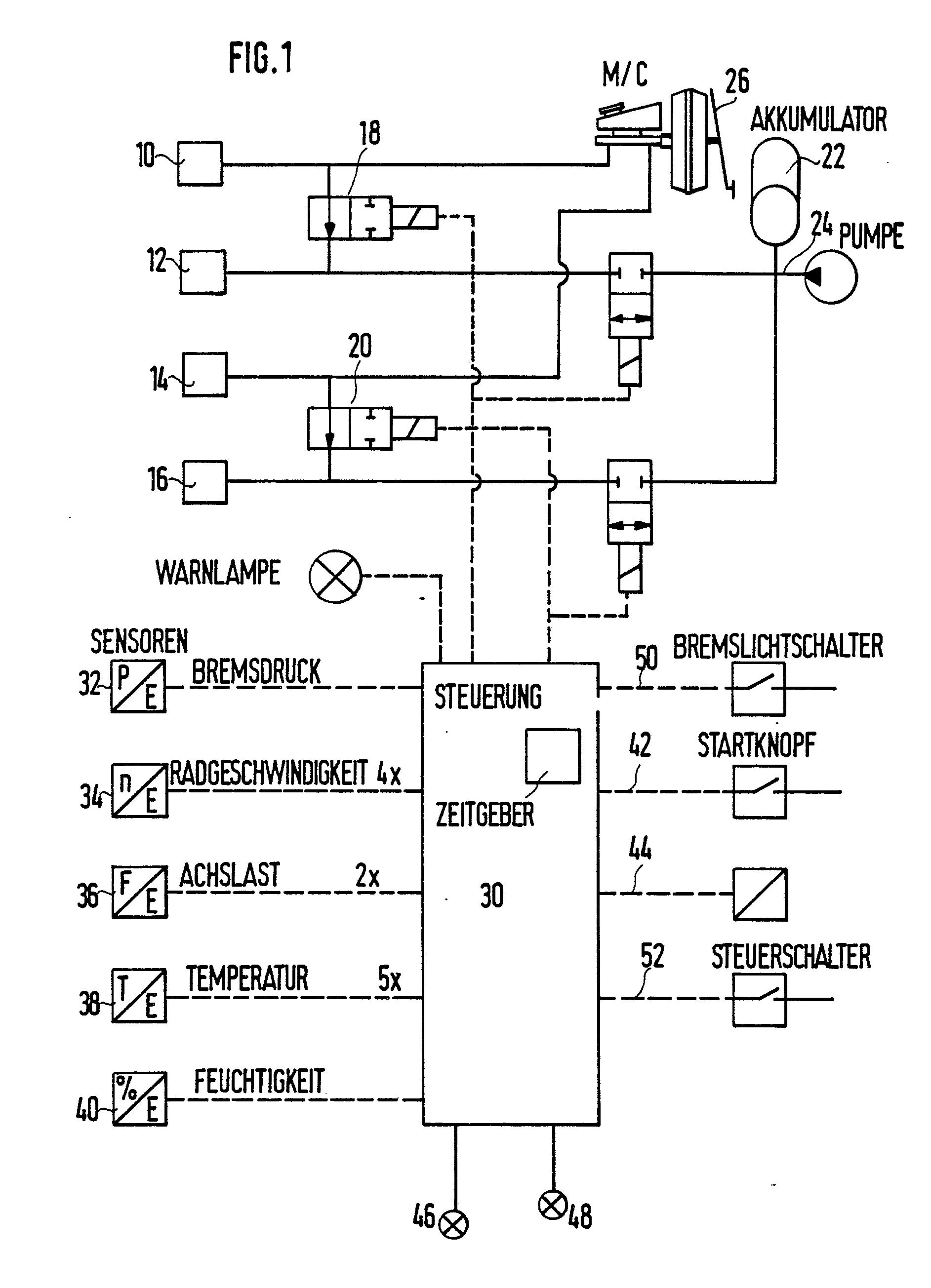
Description
Die Erfindung betrifft ein Verfahren zum Ermitteln des Reibungskoeffizienten (Haftbeiwertes) zwischen einem Fahrzeugreifen und der Fahrbahn, bei dem ein Teil der Räder des Fahrzeuges gebremst und aus deren Drehgeschwindigkeit ein Schlupf der Räder ermittelt wird.The invention relates to a method for determining the coefficient of friction (coefficient of adhesion) between a vehicle tire and the roadway, in which a part of the wheels of the vehicle is braked and a slip of the wheels is determined from the rotational speed thereof.
Ein solches Verfahren ist aus der DE-OS 31 19 153 bekannt und dient dazu, dem Fahrer die Hafteigenschaften der Fahrbahn mitzuteilen. Bei der bekannten Anordnung wird den Bremsen zur Ermittlung des Haftbeiwertes einer Fahrbahn ein automatisch mittels der zu anderen Zwecken ohnehin vorgesehenen Antiblockieranlage ein ansteigender Testdruck zugeführt und bei Erreichen eines vorbestimmten Schlupfwertes unterhalb eines vorgegebenen Testdruckwertes wird ein Warn-Signal abgegeben.Such a method is known from DE-OS 31 19 153 and serves to inform the driver of the adhesive properties of the road. In the known arrangement, the brakes for determining the adhesion coefficient of a roadway are supplied with an increasing test pressure automatically by means of the anti-lock braking system, which is provided for other purposes anyway, and a warning signal is emitted when a predetermined slip value is reached below a predetermined test pressure value.
Bei der aus der DE-OS 31 19 153 bekannten Anordnung wird der Haftbeiwert der Fahrbahn nur mit einem vorgegebenen Wert verglichen und die Anzeige informiert den Fahrer darüber, ob der Haftbeiwert größer oder kleiner als der vorgegebene Wert ist. Eine kontinuierliche Messung und Anzeige des Meßergebnisses erfolgt nicht.In the arrangement known from DE-OS 31 19 153, the coefficient of adhesion of the roadway is only compared with a predetermined value and the display informs the driver whether the coefficient of adhesion is greater or less than the predetermined value. There is no continuous measurement and display of the measurement result.
Der Erfindung liegt die Aufgabe zugrunde, das eingangs genannte Verfahren derart weiterzubilden, daß der Reibungskoeffizient zwischen den Reifen und der Fahrbahn genau gemessen und der tatsächliche Wert des Reibungskoeffizienten dem Fahrer mitgeteilt werden kann.The invention has for its object to develop the above-mentioned method such that the coefficient of friction between the tires and the road surface can be measured accurately and the actual value of the coefficient of friction can be communicated to the driver.
Erfindungsgemäße Lösungen dieser Aufgabe sind in den Ansprüchen 1, 16 und 20 gekennzeichnet.Solutions to this object according to the invention are characterized in
Die Dosierung des Bremsdruckes für das einzelne Rad ist dabei so bemessen, daß die Geradeausfahrt des Fahrzeuges nicht beeinträchtigt ist. Insbesondere kann dabei der Bremsdruck und/oder die Brems-Zeitspanne automatisch als Funktion der Geschwindigkeit variiert werden.The dosage of the brake pressure for the individual wheel is dimensioned so that the straight driving of the vehicle is not affected. In particular, the brake pressure and / or the braking time span can be varied automatically as a function of the speed.
Bevorzugt werden nacheinander die beiden nicht angetriebenen Räder des Fahrzeuges einzeln abgebremst und die reduzierte Drehgeschwindigkeit des abgebremsten Rades wird mit der des nicht abgebremsten Rades verglichen. Durch die selektive Abbremsung einzelner Räder ist es möglich, unterschiedliche Bereiche der Fahrbahn auf ihren Haftbeiwert zu untersuchen. Dem Fahrer wird der schlechtere der beiden Haftbeiwerte mitgeteilt. Auch kann dem Fahrer angezeigt werden, ob sich die an den beiden nicht angetriebenen Rädern ermittelten Reibungskoeffizienten um mehr als einen vorgegebenen Wert unterscheiden oder es können auch beide Meßergebnisse (Reibungskoeffizienten) getrennt angezeigt werden.The two non-driven wheels of the vehicle are preferably braked individually one after the other and the reduced rotational speed of the braked wheel is compared with that of the non-braked wheel. The selective braking of individual wheels makes it possible to examine different areas of the road surface for their grip. The driver is informed of the worse of the two factors of imprisonment. The driver can also be shown whether the friction coefficients determined on the two non-driven wheels differ by more than a predetermined value, or both measurement results (friction coefficients) can also be displayed separately.
Der Wert des Reibungskoeffizienten wird erfindungsgemäß genau bestimmt. Hierzu wird das Bremsmoment aus dem Produkt aus Bremsdruck, Kolbenfläche der Bremszange, Reibwert des Belages und Rad-Radius bestimmt. Der Bremsdruck am gebremsten Rad wird direkt gemessen. Die Kolbenfläche der Bremszange ist eine Konstante. Der Reibwert des Belages ist temperaturabhängig, weshalb in einer bevorzugten Ausgestaltung der Erfindung dessen Temperatur gemessen wird. Ohne eine Bestimmung der Temperatur des Belages kann auch ein unterer Mittelwert für den Reibwert angesetzt werden. Der Rad-Radius ist wiederum eine Konstante.The value of the coefficient of friction is precisely determined according to the invention. For this purpose, the braking torque is determined from the product of the brake pressure, piston area of the brake caliper, coefficient of friction of the lining and wheel radius. The brake pressure on the braked wheel is measured directly. The piston area of the brake calliper is a constant. The coefficient of friction of the lining is temperature-dependent, which is why its temperature is measured in a preferred embodiment of the invention. Without determining the temperature of the lining, a lower average value for the coefficient of friction can also be used. The wheel radius is again a constant.
Um die volle Seitenführungskraft aller Räder in einer Kurve zu behalten, ist in einer bevorzugten Ausführungsform ein Lenkwinkelschalter angebracht, der ein Einschalten des Meßsystems bei eingeschlagener Lenkung (Kurvenfahrt) verhindert.In order to keep the full cornering force of all wheels in a curve, a steering angle switch is attached in a preferred embodiment, which prevents the measuring system from being switched on when the steering is turned (cornering).
Der zu ermittelnde Reibungskoeffizient ist bei einem gegebenen Bremsmoment dem Schlupf des gebremsten Rades umgekehrt, proportional. Der Schlupf wird erfindungsgemäß derart ermittelt, daß die Drehgeschwindigkeiten des gebremsten sowie des ungebremsten Rades gemessen werden. Der Schlupf ergibt sich dann aus dem Quotienten aus der Differenz der beiden Drehgeschwindigkeiten und der Drehgeschwindigkeit des freien, ungebremsten Rades.The coefficient of friction to be determined is inversely proportional to the slip of the braked wheel for a given braking torque. According to the invention, the slip is determined in such a way that the rotational speeds of the braked and the unbraked wheel are measured. The slip then results from the quotient of the difference between the two rotational speeds and the rotational speed of the free, unbraked wheel.
In einer bevorzugten Ausgestaltung der Erfindung wird aus dem oder den Reibungskoeffizienten und der momentanen Fahrzeuggeschwindigkeit ein maximaler Bremsweg ermittelt und angezeigt.In a preferred embodiment of the invention, a maximum braking distance is determined and displayed from the friction coefficient or coefficients and the current vehicle speed.
In einer weiteren bevorzugten Ausführungsform wird der so ermittelte Bremsweg in einer an sich bekannten Radarabstandswarnanzeige aufgearbeitet und dem Fahrer wird angezeigt, ob der ermittelte Bremsweg bei der gefahrenen Geschwindigkeit ausreicht, um hinter dem vorherfahrenden Fahrzeug, dessen Geschwindigkeit durch die Radarabstandswarnanzeige ermittelt wurde, zum Stehen zu kommen, falls dieses Fahrzeug ebenfalls maximal abgebremst wird.In a further preferred embodiment, the braking distance determined in this way is processed in a radar distance warning display which is known per se and the driver is shown whether the determined braking distance at the speed traveled is sufficient to stand behind the preceding vehicle, the speed of which was determined by the radar distance warning display come if this vehicle is also braked to the maximum.
Die Ermittlung des Reibungskoeffizienten erfolgt entweder durch Betätigung einer Start-Taste seitens des Fahrers oder aber wahlweise in regelmäßigen Abständen automatisch.The friction coefficient is determined either by pressing a start button on the part of the driver or alternatively automatically at regular intervals.
Auch kann der erfindungsgemäß ermittelte Reibungskoeffizient in Beziehung zur momentanen Fahrzeuggeschwindigkeit gesetzt werden. Bei Unterschreiten eines vorgegebenen Grenzwertes des Quotienten wird ein Warnsignal abgegeben, das dem Fahrer anzeigt, daß der Bremsweg eine vorgegebene, geschwindigkeitsabhängige Strecke überschreitet.The coefficient of friction determined according to the invention can also be related to the instantaneous vehicle speed. If the quotient falls below a predefined limit value, a warning signal is issued which indicates to the driver that the braking distance exceeds a predefined, speed-dependent distance.
Das erfindungsgemäße Verfahren läßt sich bei einem Fahrzeug mit Antiblockiersystem mit wenig Aufwand durchführen, da dessen Pumpe oder Druckspeicher und Druck-Schaltventile für die einzelnen Räder verwendet werden können.The method according to the invention can be carried out with little effort in a vehicle with an anti-lock braking system, since its pump or pressure accumulator and pressure switching valves can be used for the individual wheels.
Bei den vorstehenden Verfahren zum Ermitteln des Reibungskoeffizienten zwischen Reifen und Fahrbahn kann unter bestimmten Umständen der Fahrer durch die Messung etwas irritiert werden, insbesondere dann, wenn die Messung unwillkürlich erfolgt, d.h. nicht vom Fahrer bewußt eingeleitet wird.In the above methods for determining the coefficient of friction between the tire and the road surface, the driver can be somewhat irritated by the measurement under certain circumstances, in particular if the measurement is involuntary, i.e. is not deliberately initiated by the driver.
Bei einer zusätzlichen Variante der Erfindung sollen deshalb der Fahrer oder andere Fahrzeuginsassen nicht durch den Meßvorgang irritiert werden und es soll auch die Fahrt des Fahrzeuges durch die Messung nicht beeinträchtigt werden.In an additional variant of the invention, the driver or other vehicle occupants should therefore not be irritated by the measurement process and the travel of the vehicle should not be affected by the measurement.
Gemäß einer Variante der Erfindung (Anspruch 16) ist deshalb vorgesehen, daß während einer normalen Fahrzeug-Bremsung eines der Fahrzeugräder mit einem geringeren Bremsdruck beaufschlagt wird als ein anderes Fahrzeugrad.According to a variant of the invention (claim 16) it is therefore provided that during normal vehicle braking one of the vehicle wheels is subjected to a lower braking pressure than another vehicle wheel.
Es erfolgt also die Reibungskoeffizientenmessung nicht während einer ungestörten Geradeausfahrt des Fahrzeuges, sondern nur während einer normalen Fahrzeug-Bremsung. In diesem Fall nimmt der Fahrer die Messung kaum oder gar nicht wahr.The friction coefficient measurement is therefore not carried out while the vehicle is traveling straight ahead, but only during normal vehicle braking. In this case, the driver hardly notices the measurement or not at all.
Vorteilhafte Ausgestaltungen dieser Variante des erfindungsgemäßen Verfahrens sind in den Unteransprüchen 17-19 beschrieben.Advantageous embodiments of this variant of the method according to the invention are described in subclaims 17-19.
In einer anderen erfindungsgemäßen Lösung der vorstehend genannten Aufgabe ist vorgesehen, daß für die Reibungskoeffizientenmessung die Achslast eines Fahrzeug-Rades vermindert wird, daß dieses entlastete Rad abgebremst wird und daß dessen Drehgeschwindigkeit mit der Drehgeschwindigkeit zumindest eines anderen, ungebremsten Rades verglichen wird.In another solution according to the invention of the above-mentioned object, it is provided that the axle load of a vehicle wheel is reduced for the coefficient of friction measurement, that this relieved wheel is braked and that its rotational speed is compared with the rotational speed of at least one other, unbraked wheel.
Das vorstehende erfindungsgemäße Verfahren wird in der Regel nicht bei einer normalen Fahrzeugbremsung durchgeführt, sondern kann vielmehr auch bei normaler Geradeausfahrt des Fahrzeuges angewandt werden, da das den Fahrer evtl. irritierende Rucken im Fahrzeug dadurch vermieden wird, daß die Reibung zwischen dem Meß-Rad und der Fahrbahn durch Anheben dieses Rades reduziert wird.The above method according to the invention is generally not carried out when the vehicle brakes normally, but rather can also be used when the vehicle is traveling straight ahead in a straight line, since the jerking in the vehicle which may be irritating to the driver is avoided by the fact that the friction between the measuring wheel and the road is reduced by lifting this wheel.
Es sind Kraftfahrzeuge bekannt, die aus anderen, nicht mit der Bremstechnik zusammenhängenden Gründen, die Möglichkeit haben, die Höhe eines Rades im Vergleich mit den anderen Rädern zu verändern. Die Erfindung läßt sich besonders vorteilhaft und preisgünstig bei derartigen Fahrzeugen einsetzen.Motor vehicles are known which, for other reasons not related to braking technology, have the possibility of changing the height of one wheel in comparison with the other wheels. The invention can be used particularly advantageously and inexpensively in such vehicles.
Um eine Messung im Falle einer Panik-Bremsung zu verhindern, ist in einer bevorzugten Ausgestaltung der Erfindung bei allen Varianten vorgesehen, daß nur dann eines der Fahrzeug-Räder mit geringerem Bremsdruck beaufschlagt bzw. seine Achslast vermindert wird, wenn der Druck des Hauptbremszylinders einen vorgegebenen Wert, wei z.B. 40 bar, innerhalb einer vorgegebenen Zeitspanne, wie z.B. einer Sekunde, nicht überschreitet.In order to prevent a measurement in the event of panic braking, in a preferred embodiment of the invention it is provided in all variants that only one of the vehicle wheels is subjected to a lower braking pressure or its axle load is reduced when the pressure of the master brake cylinder reaches a predetermined value Value, for example 40 bar, within a predetermined period, e.g. a second, does not exceed.
Weitere vorteilhafte Weiterbildungen des Erfindungsgedankens sind in den Unteransprüchen beschrieben.Further advantageous developments of the inventive concept are described in the subclaims.
Der Reibungskoeffizient wird bei allen erfindungsgemäßen Lösungsvarianten aus dem Schlupf des abgebremsten Rades durch Vergleich der Drehgeschwindigkeiten gewonnen. Dabei kann bei allen Lösungsvarianten der Erfindung zur Ermittlung des Reibungskoeffizienten das am abgebremsten Rad herrschende Bremsmoment, die Radlast und der aus dem -Vergleich der Drehgeschwindigkeiten der gebremsten und ungebremsten Räder gewonnene Schlupf des gebremsten Rades berücksichtigt werden. In jedem Falle kann die Ermittlung des Reibungskoeffizienten davon abhängig gemacht werden, ob der Fahrer willkürlich eine Start-Taste bzw. eine Freigabe-Taste betätigt hat.In all of the solution variants according to the invention, the coefficient of friction is obtained from the slippage of the braked wheel by comparing the rotational speeds. In all solution variants of the invention to determine the coefficient of friction, the braking torque prevailing at the braked wheel, the wheel load and the slippage of the braked wheel obtained from the comparison of the rotational speeds of the braked and unbraked wheels can be taken into account. In any case, the determination of the coefficient of friction can be made dependent on whether the driver has arbitrarily actuated a start button or a release button.
Nachfolgend sind Ausführungsbeispiele der Erfindung anhand der Zeichnung näher beschrieben.Exemplary embodiments of the invention are described in more detail below with reference to the drawing.
Es zeigt
- Rg. 1 ein Block-Schaltbild einer Vorrichtung zur Durchführung des erfindungsgemäßen Verfahrens;
- Fig. 2 eine Vorrichtung zur Entlastung eines Fahrzeug-Rades;
- Fig. 3 ein weiteres Ausführungsbeispiel einer Vorrichtung, mit der ein einzelnes Fahrzeug- Rad hinsichtlich seiner Achslast entlastet werden kann; und
- Rg. 4 ein weiteres Block-Schaltbild einer Vorrichtung, mit der während einer normalen Fahrzeug-Bremsung ein Rad mit einem bestimmten Schlupf abgebremst werden kann.
- 1 shows a block diagram of a device for carrying out the method according to the invention;
- 2 shows a device for relieving a vehicle wheel;
- Fig. 3 shows another embodiment of a device with which a single vehicle wheel can be relieved in terms of its axle load; and
- 4 shows a further block circuit diagram of a device with which a wheel can be braked with a certain slip during normal vehicle braking.
Gemäß Fig. 1 werden Bremsen 10 (vorne, links), 12 (hinten, rechts), 14 (vorne, rechts) und 16 (hinten, links) über Schaltventile 18, 20 mit Druck aus einem Druckspeicher 22 beaufschlagt. Der Druckspeicher 22 gehört zu einem (nicht gezeigten) Antiblockiersystem, dessen Steuergerät über die Druckleitung 24 angeschlossen ist (s. z.B. DE-OS 31 19153).According to FIG. 1, brakes 10 (front, left), 12 (rear, right), 14 (front, right) and 16 (rear, left) are acted upon by pressure from a
Das Bremspedal 26 ist in bekannter Weise mit den Schaltventilen 18, 20 sowie dem Antiblockiersystem verbunden.The
Ein Prozessor 30 verarbeitet Meßergebnisse und steuert die Schaltventile 18, 20 für die einzelnen Bremsen 10-16.A
Drucksensoren 32 ermitteln den Bremsdruck, insbesondere im gerade zur Ermittlung des Reibungskoeffizienten abgebremsten Rad.Pressure sensors 32 determine the brake pressure, in particular in the wheel which is just being braked to determine the coefficient of friction.
Das Meßergebnis wird in den Prozessor 30 eingegeben, welcher daraus in der eingangs angegebenen Weise das Bremsmoment berechnet. Gegebenenfalls wird hierfür auch die Temperatur der Reibbeläge mittels der Temperatur-Meßgeräte 38 gemessen.The measurement result is input into the
Weiterhin wird die Außentemperatur abgefragt und bei bestimmten kritischen Temperaturen, z.B geringer als +1°C, kann die Meßeinrichtung automatisch eingeschaltet werden.The outside temperature is also queried and at certain critical temperatures, e.g. lower than + 1 ° C, the measuring device can be switched on automatically.
Mittels der Radgeschwindigkeitssensoren 34 wird der Schlupf des gerade abgebremsten Rades durch Vergleich von dessen Radgeschwindigkeit mit der eines nicht abgebremsten Rades ermittelt. Der Schlupf ergibt sich aus der Formel:
Der Reibungskoeffizient ist bei gegebenem Bremsmoment, welches in der eingangs angegebenen Weise gemessen bzw. berechnet wird, und bei gegebener Achslast, welche mittels des Achslast-Meßgerätes 36 ermittelt und in den Prozessor 30 eingegeben wird, dem gemessenen Schlupf umgekehrt proportional. Die exakten funktionalen Zusammenhänge können experimentell ermittelt werden, so daß der Prozessor 30 mit den experimentellen Daten programmiert werden kann.The friction coefficient is inversely proportional to the measured slip for a given braking torque, which is measured or calculated in the manner specified at the beginning, and for a given axle load, which is determined by means of the axle
Feuchtigkeitsmeßgeräte 40 ermitteln die Luftfeuchtigkeit im Bereich des Rades und können bei Erreichen einer bestimmten Feuchtigkeit, z.B. 90%, das Meßprogramm automatisch in bestimmten Zeitintervallen abrufen.
Über eine vom Fahrer zu betätigende Start-taste, welche über die Leitung 42 mit dem Prozessor 30 verbunden ist, wird die' Meß-Routine ausgelöst.The 'measurement routine is triggered via a start button to be actuated by the driver, which is connected to
Die Leitung 50 führt zu den Bremslichtern oder dem Bremslichtschalter, um ein Einschalten der Meßeinrichtung zu verhindern, wenn die Betriebsbremse betätigt wird.The
Mit dem Bezugszeichen 44 ist eine Leitung für Zusatzgeräte angedeutet. Als Zusatzgerät kann eine Anzeige-Einrichtung für den momentanen, durch den Reibungskoeffizienten und die Geschwindigkeit definierten Bremsweg vorgesehen sein.The
Als Zusatzgerät kann auch eine Radarwarnanzeige angeschlossen sein (DE-OS 26 55 619), .die bei Unterschreiten eines gefährlichen Reibungskoeffizienten und Unterschreiten eines gewissen Mindestabstandes eine Zwangsbremsung auslöst.A radar warning display can also be connected as an additional device (
Als Eingang 52 ist ein Lenkwinkeischaiter vorgesehen, der das Einschalten der Meßeinrichtung verhindert, wenn ein bestimmter Lenkwinkeleinschlag überschritten wird.A steering angle switch is provided as
Eine Warnsignal-Anzeigeeinrichtung 46 leuchtet auf und/oder gibt ein Tonsignal ab, wenn der erfindungsgemäß ermittelte Reibungskoeffizient in Abhängigkeit von der momentanen Fahrzeuggeschwindigkeit einen vorgegebenen Grenzwert unterschreitet. Daneben wird der gemessene Reibungskoeffizient direkt und kontinuierlich über die Reibungskoeffizienten-Anzeigeeinrichtung 48 mitgeteilt. Es ist auch möglich, eine digitale Anzeigeeinrichtung 48 nicht in Einheiten des Reibungskoeffizienten, sondern in Einheiten des Bremsweges zu eichen.A warning
Mit der Schaltung gemäß Fig. 1 lassen sich gemäß einem anderen Ausführungsbeispiel der Erfindung die Ventile so schalten, daß während einer normalen Betriebsbremsung ein nicht angetriebenes Rad durch eines der Ventile 18 oder 20 vom Hauptbremszylinderdruck abgeschaltet wird, worauf anschließend eines der nicht angetriebenen Räder durch Druck aus der Druckquelle 22 oder 24 (Akkumulator oder Pumpe) so lange beaufschlagt wird, bis es einen bestimmten Schlupf erreicht hat. Durch Zuordnung des dafür erforderlichen Druckes unter Berücksichtigung der Achslast kann in der oben wiedergegebenen Weise der Reibungskoeffizient bestimmt werden. Als Vergleichsgeschwindigkeit für das mit dem bestimmten Schlupf laufende Fahrzeug-Rad wird das zweite, nicht angetriebene Fahrzeug-Rad herangezogen, welches ebenfalls vom Hauptbremszylinder abgetrennt und druckentlastet wurde. Es kann auch durch die anderen, mit geringem Druck abgebremsten Räder eine Bezugsgeschwindigkeit gebildet werden, die als Vergleichsgröße herangezogen wird.1, according to another embodiment of the invention, the valves can be switched such that during normal service braking, a non-driven wheel is switched off by the master cylinder pressure through one of the
Damit während einer Panikbremsung die Messung unterdrückt wird, kann ein Zeitglied vorgesehen sein, das die Messung nur zuläßt, wenn innerhalb der ersten Sekunde der Bremsbetätigung z.B. 40 bar nicht überschritten werden.So that the measurement is suppressed during panic braking, a timer can be provided which only allows the measurement if, for example, within the first second of the brake application Not exceed 40 bar.
Der wie vorstehend ermittelte Reibungskoeffizient kann abgespeichert und zur Berechnung des momentanen Bremsweges für eine Bremsweganzeige oder auch eine Abstands-Wamanzeige herangezogen werden.The friction coefficient as determined above can be stored and used to calculate the current braking distance for a braking distance display or a distance warning display.
Fig. 2 illustriert ein anderes Verfahren zum Ermitteln des Reibungskoeffizienten zwischen Reifen und Fahrbahn, bei dem ebenfalls die Beeinträchtigung der Fahrt des Fahrzeuges und somit ein mögliche Irritierung der Fahrzeuginsassen auf ein Minimum reduziert sind.FIG. 2 illustrates another method for determining the coefficient of friction between the tire and the roadway, in which the impairment of the driving of the vehicle and thus a possible irritation of the vehicle occupants are also reduced to a minimum.
Gemäß Fig. 2 wird bei einem Fahrzeug mit Längslenker ein Hubzylinder 80 vorgesehen, der während des normalen Fahrbetriebes drucklos ist und bei dem zwischen zwei Kammern 82 und 84 eine leitende Verbindung besteht. Vor einer Messung des Reibungskoeffizienten wird die Kammer 82 mit Druckflüssigkeit aus einem nicht gezeigten Speicher beaufschlagt und das Ventil 85 zwischen den Kammern geschlossen, während die Kammer 84 mit einem Reservoir verbunden ist. Sobald die vorgegebene, vom Last-Sensor 86 ermittelte Radlast erreicht ist, wird die Messung des Reibungskoeffizienten eingeleitet. Hierzu wird das in der vorstehend beschriebenen Weise gelüftete Rad, welches selbstverständlich weiterhin Bodenkontakt hat, abgebremst und es werden die Drehgeschwindigkeiten mit den nicht gebremsten Rädern wie oben angegeben verglichen.2, a lifting
Für die Messung des Reibungskoeffizienten ist nur eine sehr kurze Zeitspanne erforderlich, so daß durch das Anheben bzw. das Entlasten des Rades das Fahrverhalten des Fahrzeuges kaum beeinflußt wird. In einer Kurve werden derartige Messungen unterdrückt. Hierzu ist beispielsweise ein Lenkrad-Sensor vorgesehen. Auch können z.B. die Achslasten verglichen werden.Only a very short period of time is required to measure the coefficient of friction, so that the driving behavior of the vehicle is hardly influenced by lifting or relieving the load on the wheel. Such measurements are suppressed in a curve. For example, a steering wheel sensor is provided for this purpose. Also e.g. the axle loads are compared.
Fig. 3 zeigt ein Fahrzeug mit hydropneumatischer Federung, bei dem die Entlastung des für die Messung herangezogenen Rades dadurch erreicht wird, daß der Druck auf der einen Aufhängungsseite erhöht wird, so daß die andere Aufhängungsseite entlastet wird. Die beiden Räder HL (hinten, links) und HR (hinten, rechts) werden hierfür mittels der hydraulischen Kolban/Zylinder-Anordnungen 87 bzw. 8T mittels der Steuereinrichtung 89 wahlweise angehoben.Fig. 3 shows a vehicle with hydropneumatic suspension, in which the relief of the wheel used for the measurement is achieved by increasing the pressure on one side of the suspension, so that the other side of the suspension is relieved. For this purpose, the two wheels HL (rear, left) and HR (rear, right) are optionally raised by means of the hydraulic piston /
Fig. 4 zeigt ein Block-Diagramm einer Vorrichtung, mit welcher die Reibungskoeffizientenmessung während einer normalen Betriebsbremsung durchgeführt werden kann. Bei diesem Ausführungsbeispiel wird also die Achslast keines Rades vermindert, vielmehr wird der Reibungskoeffizient entsprechend dem anhand Fig. 1 beschriebenen Ausführungsbeispiel ermittelt Es sind die Bremsen hinten links (HL) und hinten rechts - (HR) gezeigt Die beiden Steuerventile 90, 92 haben drei Stellungen 1, 2 und 3. In der Stellung 1 - (Normalstellung) ist die Bremse mit dem Hauptbremszylinder verbunden und die Druckquelle 94 ist gesperrt. Es erfolgt eine normale Bremswirkung. Auch die Tankverbindung 96 ist gesperrt In der zweiten Stellung (Tesistellung) ist die Bremse mit der Druckquelle 94 verbunden und es erfolgt ein gesteuerter Druckanstieg, der durch den Druckaufnehmer 98 überwacht wird. Der Hauptbremszylinder und die Tankanschlüsse sind ebenfalls gesperrt. In einer dritten Stellung (Bremsentlastung) wird die Bremse mit dem Tank durch eine Drossel 96 verbunden. Der Hauptbremszylinder und die Druckquelle 94 sind gesperrt. Die Anschlüsse des Hauptbremszylinders sind mit Hz (Prim. = primärseitig) und Hz (Sek. = sekundärseitig) bezeichnet. Bei der Messung des Reibungskoeffizienten auf der linken Seite ist das linke Steuerventil 90 in Stellung 2, während das rechte Ventil 92 in Stellung 3 ist. Bei einer Messung auf der rechten Seite befindet sich das rechte Ventil 92 in Stellung 3 und das linke Ventil 90 in Stellung 2. Nach dem Test kehrt es in Stellung 3 zurück. Die Rückschlagventile 100, 102 trennen die Hinterachs-Bremskreise (sogenannter X-Split).FIG. 4 shows a block diagram of a device with which the coefficient of friction measurement can be carried out during normal service braking. In this embodiment, therefore, the axle load of no wheel is reduced, rather the coefficient of friction is determined in accordance with the embodiment described with reference to FIG. 1. The brakes are shown at the rear left (HL) and rear right (HR). The two
Claims (22)
dadurch gekennzeichnet, daß jeweils ein einziges Rad abgebremst und dessen Drehgeschwindigkeit mit der Drehgeschwindigkeit zumindest eines anderen, ungebremsten Rades verglichen wird.1. A method for determining the coefficient of friction between a vehicle tire and the roadway, in which a part of the wheels of the vehicle is braked and a slip of the wheels is determined from the speed of rotation thereof,
characterized, that a single wheel is braked and its rotational speed is compared with the rotational speed of at least one other, unbraked wheel.
dadurch gekennzeichnet,
daß nacheinander zumindest zwei Räder des Fahrzeuges, vorzugsweise nicht angetriebene Räder, selektiv abgebremst werden, deren Drehgeshwindigkeit jeweils mit der von zumindest einem anderen, nicht abgebremsten Rad verglichen wird.2. The method according to claim 1,
characterized,
that successively at least two wheels of the vehicle, preferably non-driven wheels, are braked selectively, the rotational speed of which is compared in each case with that of at least one other, non-braked wheel.
dadurch gekennzeichnet,
daß die Drehgeschwindigkeit des gerade gebremsten Rades mit der des gerade nicht gebremsten Rades verglichen wird.3. The method according to claim 2,
characterized,
that the speed of rotation of the wheel just braked is compared to that of the wheel just not braked.
dadurch gekennzeichnet,
daß bei der Ermittlung des Reibungskoeffizienten das am abgebremsten Rad herrschende Bremsmoment, die Radlast und der aus dem Vergleich der Drehgeschwindigkeiten der gebremsten und ungrebemsten Räder gewonnene Schlupf des gebremsten Rades berücksichtigt werden, wobei insbesondere bei der Ermittlung des am gebremsten Rad herrschenden Bremsmomentes der Reibwert der Beläge durch Messung von deren Temperatur und/oder die am gebremsten Rad wirkende Achslast gemessen und berücksichtigt werden.4. The method according to claim 1,
characterized,
that when determining the coefficient of friction the braking torque prevailing on the braked wheel, the wheel load and the slippage of the braked wheel obtained from the comparison of the rotational speeds of the braked and unbraked wheels are taken into account, in particular when determining the braking torque prevailing on the braked wheel the friction coefficient of the linings be measured and taken into account by measuring their temperature and / or the axle load acting on the braked wheel.
dadurch gekennzeichnet,
daß die Bremsung am ausgewählten Rad mit einem Bremsdruck und über eine Zeitspanne erfolgt, die so bemessen sind, daß die Geradeausfahrt des Fahrzeuges nicht erheblich gestört wird.5. The method according to claim 1,
characterized,
that braking is carried out on the selected wheel with a braking pressure and over a period of time which are dimensioned such that the straight-ahead driving of the vehicle is not significantly disturbed.
dadurch gekennzeichnet,
daß der Bremsdruck und/oder die Brems-Zeitspanne automatisch als Funktion der Fahrzeuggeschwindigkeit variiert werden.6. The method according to claim 5,
characterized,
that the brake pressure and / or the braking period are varied automatically as a function of the vehicle speed.
dadurch gekennzeichnet,
daß ein Warn-Signal bei Unterschreiten eines vorgegebenen Reibungskoeffizienten abgegeben wird, wobei bei Bestimmung mehrerer Reibungskoeffizienten der kleinste Meßwert herangezogen wird.7. The method according to claim 1,
characterized,
that a warning signal is emitted when a predetermined coefficient of friction is undershot, the smallest measured value being used when determining several coefficients of friction.
dadurch gekennzeichnet,
daß ein Warn-Signal bei Überschreiten einer vorgegebenen maximalen Differenz der Reibungskoeffizienten verschiedener Räder abgegeben wird.8. The method according to claim 1,
characterized,
that a warning signal is given when a predetermined maximum difference in the friction coefficients of different wheels is exceeded.
dadurch gekennzeichnet,
daß aus dem Reibungskoeffizienten und der Fahrzeuggeschwindigkeit ein zu erwartender Bremsweg ermittelt und angezeigt wird. Verfahren nach Anspruch.1, - -
dadurch gekennzeichnet,
daß die Ermittlung des Reibungskoeffizienten durch eine von Hand betätigbare Start-Taste eingeleitet wird.9. The method according to claim 1,
characterized,
that an expected braking distance is determined and displayed from the coefficient of friction and the vehicle speed. Method according to claim 1, -
characterized,
that the determination of the coefficient of friction is initiated by a manually operated start button.
dadurch gekennzeichnet,
daß ein ermittelter maximaler Bremsweg in einer Radarabstandswarnanzeigeeinrichtung verarbeitet wird und bei Unterschreiten eines kritischen Abstands eine Warnung ausgelöst wird.11. The method according to claim 1,
characterized,
that a determined maximum braking distance is processed in a radar distance warning device and a warning is triggered when the distance falls below a critical distance.
dadurch gekennzeichnet,
daß bei Unterschreiten eines bestimmten Abstandes eine Zwangsbremsung ausgelöst wird.12.The method according to claim 1,
characterized,
that emergency braking is triggered when the distance falls below a certain distance.
dadurch gekennzeichnet,
daß ab einem bestimmten Lenkwinkeleinschlag ein Auslösen der Meßvorrichtung verhindert wird.13. The method according to claim 1,
characterized,
that triggering of the measuring device is prevented from a certain steering angle.
dadurch gekennzeichnet,
daß bei Überschreiten einer bestimmten Luftfeuchtigkeit, z.B. 90%, das Meßverfahren automatisch periodisch ausgelöst wird.14. The method according to claim 1,
characterized,
that when a certain air humidity is exceeded, eg 90%, the measuring process is automatically triggered periodically.
dadurch gekennzeichnet,
daß bei Unterschreiten einer bestimmten Temperatur, z.B. +2°C, das Meßverfahren automatisch eingeleitet wird.15. The method according to claim 1,
characterized,
that the measuring process is automatically initiated when the temperature falls below a certain level, eg + 2 ° C.
dadurch gekennzeichnet,
daß während einer normalen Fahrzeug-Bremsung eines der Fahrzeug-Räder mit einem geringeren Bremsdruck beaufschlagt wird als ein anderes Fahrzeug-Rad.16. A method for determining the coefficient of friction between a vehicle tire and the roadway, in which at least one vehicle wheel is braked and at least one other vehicle wheel is not or less braked and a slip is determined from a comparison of the rotational speeds of these wheels.
characterized,
that during normal vehicle braking, one of the vehicle wheels is subjected to a lower braking pressure than another vehicle wheel.
dadurch gekennzeichnet,
daß das mit geringerem Bremsdruck beaufschlagte Fahrzeug-Rad nicht gebremst wird.17. The method of claim 16
characterized,
that the vehicle wheel loaded with lower brake pressure is not braked.
dadurch gekennzeichnet,
daß das mit geringerem Bremsdruck beaufschlagte Fahrzeug-Rad und das mit stärkerem Bremsdruck beaufschlagte Fahrzeug-Rad jeweils nicht angetriebene Räder des Fahrzeuges sind.18. The method according to claim 16,
characterized,
that the vehicle wheel with a lower brake pressure and the vehicle wheel with a higher brake pressure are each non-driven wheels of the vehicle.
dadurch gekennzeichnet, daß das mit stärkerem Bremsdruck beaufschlagte Fahrzeug-Rad solange mit steigendem Bremsdruck beaufschlagt wird, bis es einen vorgegebenen Schlupf erreicht hat.19. The method according to claim 16,
characterized in that the vehicle wheel subjected to a greater braking pressure is subjected to increasing braking pressure until it has reached a predetermined slip.
dadurch gekennzeichnet,
daß die Achslast eines Fahrzeug-Rades vermindert wird, daß dieses entlastete Fahrzeug-Rad abgebremst wird und daß dessen Drehgeschwindigkeit mit der Drehgeschwindigkeit zumindest eines anderen, ungebremsten Rades verglichen wird.20. A method for determining the coefficient of friction between a vehicle tire and the roadway, in which at least one vehicle wheel is braked and at least one other vehicle wheel is not or less braked and a slip is determined from a comparison of the rotational speeds of these wheels.
characterized,
that the axle load of a vehicle wheel is reduced, that this relieved vehicle wheel is braked and that its rotational speed is compared with the rotational speed of at least one other, unbraked wheel.
dadurch gekennzeichnet,; _ daß aus dem ermittelten Reibungskoeffizienten ein Bremsweg errechnet und angezeigt wird.21. The method according to claim 20,
characterized,; _ that a braking distance is calculated and displayed from the determined coefficient of friction.
dadurch gekennzeichnet,
daß nur dann eines der Fahrzeug-Räder mit geringerem Bremsdruck beaufschlagt oder seine Achslast vermindert wird, wenn der Druck des Hauptbremszylinders einen vorgegebenen Wert, wie z.B. 40 bar, innerhalb einer vorgegebenen Zeitspanne, wie z.B. einer Sekunde, nicht überschreitet.22. The method according to claim 20,
characterized,
that only one of the vehicle wheels is subjected to a lower brake pressure or its axle load is reduced if the pressure of the master brake cylinder does not exceed a predetermined value, such as 40 bar, within a predetermined time period, such as a second.
dadurch gekennzeichnet,
daß das entlastete Fahrzeug-Rad ein nicht angetriebenes Rad ist.23. The method according to claim 20,
characterized,
that the relieved vehicle wheel is a non-driven wheel.
Applications Claiming Priority (4)
| Application Number | Priority Date | Filing Date | Title |
|---|---|---|---|
| DE3516399 | 1985-05-07 | ||
| DE19853516399 DE3516399A1 (en) | 1985-05-07 | 1985-05-07 | Method for determining the coefficient of friction between tyre and carriageway |
| DE19853534022 DE3534022A1 (en) | 1985-05-07 | 1985-09-24 | METHOD FOR DETERMINING THE FRICTION COEFFICIENT BETWEEN TIRES AND ROAD |
| DE3534022 | 1985-09-24 |
Publications (3)
| Publication Number | Publication Date |
|---|---|
| EP0201843A2 true EP0201843A2 (en) | 1986-11-20 |
| EP0201843A3 EP0201843A3 (en) | 1988-05-25 |
| EP0201843B1 EP0201843B1 (en) | 1991-08-07 |
Family
ID=25832030
Family Applications (1)
| Application Number | Title | Priority Date | Filing Date |
|---|---|---|---|
| EP86106168A Expired - Lifetime EP0201843B1 (en) | 1985-05-07 | 1986-05-06 | Friction coefficient searching method between tyres and runway |
Country Status (4)
| Country | Link |
|---|---|
| US (1) | US4779447A (en) |
| EP (1) | EP0201843B1 (en) |
| JP (1) | JPH0723861B2 (en) |
| DE (2) | DE3534022A1 (en) |
Cited By (11)
| Publication number | Priority date | Publication date | Assignee | Title |
|---|---|---|---|---|
| WO1989001888A1 (en) * | 1987-08-28 | 1989-03-09 | Robert Bosch Gmbh | Process for determining the coefficient of friction |
| WO1989003780A1 (en) * | 1987-10-22 | 1989-05-05 | Robert Bosch Gmbh | PROCESS FOR CONTINUOUS DETERMINATION OF THE ADHESION COEFFICIENT $G(m) AND/OR THE SLOPE Kmu of the mu SLIP CURVE |
| WO1989009710A1 (en) * | 1988-04-07 | 1989-10-19 | Oddvard Johnsen | Method and system for non-locking and non-skidding braking/traction of a vehicle wheel |
| EP0323066A3 (en) * | 1987-12-28 | 1990-02-07 | Ford Motor Company Limited | Automotive system for dynamically determining road adhesautomotive system for dynamically determining road adhesion ion |
| WO1991008129A1 (en) * | 1989-12-02 | 1991-06-13 | Robert Bosch Gmbh | Device for determining the adhesion between a tyre and a road surface |
| FR2660270A1 (en) * | 1990-04-02 | 1991-10-04 | Volkswagen Ag | METHOD FOR CONTROLLING THE ADHESION BETWEEN THE PASSENGER AND THE PNEUMATIC TIRES OF A MOTOR VEHICLE. |
| EP0393375A3 (en) * | 1989-04-17 | 1992-11-19 | Daimler-Benz Aktiengesellschaft | Procedure for determining the wheel slip for each wheel of a vehicle |
| EP0392164A3 (en) * | 1989-04-12 | 1993-05-19 | Bayerische Motoren Werke Aktiengesellschaft | Procedure for determining the friction value between the road and the vehicle tires |
| DE4217710A1 (en) * | 1992-06-01 | 1993-12-02 | Porsche Ag | Method for recognizing a winter slick road |
| WO1998014356A1 (en) * | 1996-09-30 | 1998-04-09 | Daimler-Benz Aktiengesellschaft | Control system for brake power proportioning on a road vehicle |
| FR2915802A1 (en) * | 2007-05-04 | 2008-11-07 | Peugeot Citroen Automobiles Sa | Wheel's adhesion determining method for motor vehicle, involves applying braking action on one of wheels of vehicle, measuring parameter varying according to brake, and determining value of adhesion coefficient from measured parameter |
Families Citing this family (47)
| Publication number | Priority date | Publication date | Assignee | Title |
|---|---|---|---|---|
| JP2681930B2 (en) * | 1987-06-27 | 1997-11-26 | 株式会社デンソー | Servo control device |
| DE3805589A1 (en) * | 1988-02-23 | 1989-08-31 | Lucas Ind Plc | METHOD AND DEVICE FOR CONTROLLING A BRAKE SYSTEM FOR HEAVY VEHICLES |
| NO165856C (en) * | 1988-04-07 | 1991-04-17 | Oddvard Johnsen | PROCEDURE AND DEVICE FOR USE IN DETERMINING PATH FRICTION AND BRAKE CONDITIONS. |
| EP0363570B1 (en) * | 1988-10-13 | 1996-02-21 | Japan Electronics Industry, Ltd. | Road surface friction sensor and road surface friction coefficient detector, and vehicle antilock braking device |
| US5216608A (en) * | 1990-01-25 | 1993-06-01 | Mitsubishi Jidosha Kogyo Kabushiki Kaisha | Apparatus and a method for estimating the friction coefficient of a road surface and controlling a driving condition of a vehicle in accordance with the estimated friction coefficient |
| US4995197A (en) * | 1990-01-29 | 1991-02-26 | Shieh Chiung Huei | Method of abrading |
| DE4010212A1 (en) * | 1990-03-30 | 1991-10-02 | Bosch Gmbh Robert | METHOD FOR DETERMINING THE FINAL VALUE ADJUSTMENT (MY) |
| US5132906A (en) * | 1990-06-11 | 1992-07-21 | Ford Motor Company | Road surface friction and hill slope estimator |
| DE4024815A1 (en) * | 1990-08-04 | 1992-02-13 | Bosch Gmbh Robert | SPEED ESTIMATION METHOD |
| DE4026625A1 (en) * | 1990-08-23 | 1992-02-27 | Bosch Gmbh Robert | Friction coefficient measurement for vehicle wheel - by dividing detected resetting torque acting on stereo wheel by detected standing force exerted on tyre |
| JPH04345562A (en) * | 1991-05-23 | 1992-12-01 | Jidosha Kiki Co Ltd | Judging method for friction factor of road surface and anti-skid brake control method using method thereof |
| DE69229634T2 (en) * | 1991-11-29 | 2000-02-24 | Mitsubishi Jidosha Kogyo K.K., Tokio/Tokyo | METHOD AND DEVICE FOR REGULATING THE BRAKE FORCE OF THE REAR WHEELS |
| US5417482A (en) * | 1991-12-24 | 1995-05-23 | Kayaba Kogyo Kabushiki Kaisha | Antilock mechanism for motorcycle brakes |
| US5245856A (en) * | 1992-01-13 | 1993-09-21 | Randy Pazzaglia | Portable testing device for measuring static and dynamic drag fractors |
| US5220307A (en) * | 1992-01-23 | 1993-06-15 | Zexel-Gleason Usa, Inc. | Warning system distinguishing wheel skidding and wheel slipping |
| DE4312404A1 (en) * | 1993-04-16 | 1994-10-20 | Teves Gmbh Alfred | External brake system for motor vehicles |
| DE4435448B4 (en) * | 1993-10-13 | 2007-10-11 | Volkswagen Ag | Method for permanent determination of the road friction coefficient |
| US6276189B1 (en) | 1995-03-13 | 2001-08-21 | James Kevin Hurson | Method and apparatus for continuous monitoring of road surface friction |
| DE19530632A1 (en) * | 1995-08-21 | 1997-02-27 | Wabco Gmbh | Procedure for determining the coefficient of friction used between the wheel and the road |
| JP3633120B2 (en) * | 1996-07-18 | 2005-03-30 | 日産自動車株式会社 | Vehicle speed and road friction coefficient estimation device |
| DE19648033A1 (en) * | 1996-11-20 | 1998-05-28 | Zahnradfabrik Friedrichshafen | Brake control/monitoring method for heavy motor vehicle |
| US6220676B1 (en) * | 1997-05-09 | 2001-04-24 | The B. F. Goodrich Company | Antiskid control of multi-wheel vehicles using coupled and decoupled Kalman filtering incorporating pitch weight transfer |
| US5864056A (en) * | 1998-02-17 | 1999-01-26 | Bell; Larry D. | Method and apparatus for monitoring the coefficient of friction between a tire and rolling surface, particularly to provide the vehicle operator with coefficient of friction, tire tread wear out and skid warning indications |
| EP1097054B1 (en) * | 1998-07-17 | 2004-01-07 | Continental Teves AG & Co. oHG | Method and device for determining a parameter for an instantaneously maximal frictional force coefficient |
| DE19834167B4 (en) * | 1998-07-29 | 2007-01-18 | Volkswagen Ag | Method and device for adjusting the braking power to current wheel-road-traction conditions |
| US6192736B1 (en) | 1998-09-23 | 2001-02-27 | Diversified Metal Fabricators, Inc. | Tribometer for testing the efficiency of lubrication upon a railroad track surface |
| DE19844493A1 (en) * | 1998-09-29 | 2000-03-30 | Zahnradfabrik Friedrichshafen | Hydropneumatic suspension system |
| JP2000190836A (en) * | 1998-12-25 | 2000-07-11 | Aisin Seiki Co Ltd | Friction coefficient peak estimating device and anti-skid control device provided with the estimating device |
| JP2001047822A (en) * | 1999-08-10 | 2001-02-20 | Toyo Tire & Rubber Co Ltd | Analysis method for frictional energy of rolling tires |
| GB2353573B (en) * | 1999-08-24 | 2002-01-02 | Bosch Gmbh Robert | Method and device for adjusting the braking action at the wheels of a motor vehicle |
| SE518551C2 (en) * | 2000-02-14 | 2002-10-22 | Scania Cv Ab | Device for estimating the level of friction between a vehicle's wheel and ground support |
| US6681614B1 (en) * | 2000-09-06 | 2004-01-27 | Daniel L. Riffe | Apparatus for testing co-efficient of friction of a road surface |
| DE10146950B4 (en) * | 2001-03-22 | 2016-10-06 | Continental Teves Ag & Co. Ohg | Control method for an electronically controlled brake system |
| SE0101247L (en) * | 2001-04-09 | 2002-10-10 | Scania Cv Ab | Method and apparatus for generating a slip warning signal |
| DE10307510A1 (en) * | 2003-02-21 | 2004-09-09 | Knorr-Bremse Systeme für Nutzfahrzeuge GmbH | Method and device for computer-aided calculation of the axle loads of a vehicle |
| EP1481861B1 (en) * | 2003-05-28 | 2007-07-04 | Ford Global Technologies, LLC | A method and a computer readable storage device for estimating tirc-to-road friction |
| EP1637863A1 (en) * | 2004-09-20 | 2006-03-22 | PIRELLI PNEUMATICI S.p.A. | Method for calculating a friction-slippage curve for a tire |
| GB2419962B (en) * | 2004-11-03 | 2010-04-14 | Douglas Equipment Ltd | Surface friction measuring device |
| NO323337B1 (en) * | 2005-10-06 | 2007-03-26 | Thor Wiggo Olsen | Method and apparatus for measuring friction on a road surface |
| US7617721B2 (en) | 2006-10-02 | 2009-11-17 | 3Rd Millennium Solutions, Ltd. | Apparatus and methods for determining a predicted vehicle braking operation |
| EP2241462A4 (en) * | 2008-02-07 | 2012-10-03 | Equos Res Co Ltd | CONTROL DEVICE AND VEHICLE |
| DE102009046448A1 (en) * | 2009-11-06 | 2011-05-12 | Robert Bosch Gmbh | Method and device for determining the speed of a motor vehicle |
| DE102010036638A1 (en) * | 2010-07-27 | 2012-02-02 | Dr. Ing. H.C. F. Porsche Aktiengesellschaft | Method for determining the coefficient of friction in a vehicle |
| US8886432B2 (en) * | 2012-07-20 | 2014-11-11 | GM Global Technology Operations LLC | Vehicle brake system and method of operating the same |
| GB2531572B (en) * | 2014-10-22 | 2017-01-11 | Wdm Ltd | Friction Tester |
| DE102016211728A1 (en) * | 2016-06-29 | 2018-01-04 | Trw Automotive U.S. Llc | Reibwertschätzer |
| FR3076047B1 (en) * | 2017-12-22 | 2021-01-08 | Michelin & Cie | PROCESS FOR MANAGING A PLATOON OF TRUCKS BASED ON INFORMATION RELATING TO THE TIRES EQUIPPING THE TRUCKS DUDIT PLATOON |
Family Cites Families (15)
| Publication number | Priority date | Publication date | Assignee | Title |
|---|---|---|---|---|
| US2305789A (en) * | 1938-07-25 | 1942-12-22 | Kempf Hermann | Speed and braking distance indicator |
| FR994290A (en) * | 1946-10-08 | 1951-11-14 | Adherometer for vehicles | |
| DE1959734C3 (en) * | 1969-11-28 | 1974-04-04 | Fritz 2000 Hamburg Reinecken | Device for determining the friction conditions between a pair of wheels and a bearing surface |
| US3825304A (en) * | 1971-05-27 | 1974-07-23 | Sauget A | Method of electrically controlling braking of a vehicle and an electronically controlled braking device for a vehicle |
| US3893330A (en) * | 1972-12-18 | 1975-07-08 | Data Systems Inc | Surface friction testing |
| JPS5634812B2 (en) * | 1974-06-07 | 1981-08-13 | ||
| JPS5238977A (en) * | 1975-09-23 | 1977-03-25 | Nippon Soken Inc | Braking stop distance device |
| DE2544842A1 (en) * | 1975-10-07 | 1977-04-21 | Bosch Gmbh Robert | METHOD AND CIRCUIT ARRANGEMENT FOR EVALUATING SIGNAL PULSE SEQUENCES, IN PARTICULAR RADAR PULSE SEQUENCES |
| SE407856B (en) * | 1976-03-31 | 1979-04-23 | Saab Scania Ab | IN THE MATTER OF A MOTOR VEHICLE WITH AT LEAST ONE INTEGRATED METH WHEEL META AND INDICATE THE LIMIT VALUE FOR DRIVING AND BRAKING OF VEHICLES ON RADING SUBSTRATES AND METHOD DEVICE FOR PERFORMING THE SET |
| IE45011B1 (en) * | 1976-11-26 | 1982-06-02 | Pcb Controls Ltd | Anti-skid control method and system for a brake equipped vehicle wheel |
| US4212063A (en) * | 1978-09-06 | 1980-07-08 | Saab-Scania Aktiebolag | Apparatus for measuring the action of forces between wheeled vehicles and substructure |
| DE2947259A1 (en) * | 1979-11-23 | 1981-05-27 | Daimler-Benz Ag, 7000 Stuttgart | Determining coefficient of friction of motor vehicle - using force measuring device on distance piece between wheels or skids |
| DE3119153A1 (en) * | 1981-05-14 | 1982-12-02 | Robert Bosch Gmbh, 7000 Stuttgart | ARRANGEMENT FOR DETERMINING THE ADHESIVE VALUE OF A TRAMWAY |
| SE436804B (en) * | 1983-05-13 | 1985-01-21 | Inventab Electronic Ab | SET FOR INDICATING SLIRING BY A DRIVING ROTATION BODY |
| US4662211A (en) * | 1985-12-16 | 1987-05-05 | K. J. Law Engineers, Inc. | Measuring friction characteristics of vehicle travel surfaces |
-
1985
- 1985-09-24 DE DE19853534022 patent/DE3534022A1/en not_active Withdrawn
-
1986
- 1986-05-06 EP EP86106168A patent/EP0201843B1/en not_active Expired - Lifetime
- 1986-05-06 DE DE8686106168T patent/DE3680710D1/en not_active Expired - Lifetime
- 1986-05-07 JP JP10458586A patent/JPH0723861B2/en not_active Expired - Lifetime
-
1987
- 1987-05-28 US US07/055,161 patent/US4779447A/en not_active Expired - Lifetime
Cited By (12)
| Publication number | Priority date | Publication date | Assignee | Title |
|---|---|---|---|---|
| WO1989001888A1 (en) * | 1987-08-28 | 1989-03-09 | Robert Bosch Gmbh | Process for determining the coefficient of friction |
| WO1989003780A1 (en) * | 1987-10-22 | 1989-05-05 | Robert Bosch Gmbh | PROCESS FOR CONTINUOUS DETERMINATION OF THE ADHESION COEFFICIENT $G(m) AND/OR THE SLOPE Kmu of the mu SLIP CURVE |
| EP0323066A3 (en) * | 1987-12-28 | 1990-02-07 | Ford Motor Company Limited | Automotive system for dynamically determining road adhesautomotive system for dynamically determining road adhesion ion |
| WO1989009710A1 (en) * | 1988-04-07 | 1989-10-19 | Oddvard Johnsen | Method and system for non-locking and non-skidding braking/traction of a vehicle wheel |
| EP0392164A3 (en) * | 1989-04-12 | 1993-05-19 | Bayerische Motoren Werke Aktiengesellschaft | Procedure for determining the friction value between the road and the vehicle tires |
| EP0393375A3 (en) * | 1989-04-17 | 1992-11-19 | Daimler-Benz Aktiengesellschaft | Procedure for determining the wheel slip for each wheel of a vehicle |
| WO1991008129A1 (en) * | 1989-12-02 | 1991-06-13 | Robert Bosch Gmbh | Device for determining the adhesion between a tyre and a road surface |
| FR2660270A1 (en) * | 1990-04-02 | 1991-10-04 | Volkswagen Ag | METHOD FOR CONTROLLING THE ADHESION BETWEEN THE PASSENGER AND THE PNEUMATIC TIRES OF A MOTOR VEHICLE. |
| DE4217710A1 (en) * | 1992-06-01 | 1993-12-02 | Porsche Ag | Method for recognizing a winter slick road |
| WO1998014356A1 (en) * | 1996-09-30 | 1998-04-09 | Daimler-Benz Aktiengesellschaft | Control system for brake power proportioning on a road vehicle |
| US6312065B1 (en) | 1996-09-30 | 2001-11-06 | Rainer Freitag | Control system for brake power proportioning on a road vehicle |
| FR2915802A1 (en) * | 2007-05-04 | 2008-11-07 | Peugeot Citroen Automobiles Sa | Wheel's adhesion determining method for motor vehicle, involves applying braking action on one of wheels of vehicle, measuring parameter varying according to brake, and determining value of adhesion coefficient from measured parameter |
Also Published As
| Publication number | Publication date |
|---|---|
| EP0201843A3 (en) | 1988-05-25 |
| JPH0723861B2 (en) | 1995-03-15 |
| DE3680710D1 (en) | 1991-09-12 |
| EP0201843B1 (en) | 1991-08-07 |
| DE3534022A1 (en) | 1987-03-26 |
| US4779447A (en) | 1988-10-25 |
| JPS61256240A (en) | 1986-11-13 |
Similar Documents
| Publication | Publication Date | Title |
|---|---|---|
| EP0201843B1 (en) | Friction coefficient searching method between tyres and runway | |
| EP0393375B1 (en) | Procedure for determining the wheel slip for each wheel of a vehicle | |
| DE69019320T2 (en) | Method and device for regulating the articulation angle in trucks. | |
| EP1142768B1 (en) | Method for preventing the overturning of a vehicle about its longitudinal axis | |
| EP0630786B1 (en) | Process and circuit for determining the friction value | |
| EP1427619B1 (en) | Method for stabilizing the driving state of a utility vehicle combination | |
| EP0418264B1 (en) | Process for enhancing control over a braked vehicle | |
| EP2750942B1 (en) | Method for warning the driver of a vehicle of a risk of overturning and control device therefor | |
| DE69709417T2 (en) | Method for evaluating signals from a tire pressure monitoring device of a moving vehicle | |
| EP0563596B1 (en) | Procedure for determination of brake reference values | |
| EP1628862A1 (en) | Method and device for determining a friction value representing frictions acting between a road and vehicle tires | |
| DE4114047A1 (en) | Electronic control system for vehicular braking or traction - reacts to detected wheel speed difference in periods free from steering, hill-climbing, wheel-slip or lock | |
| EP1045783B1 (en) | Device and method for limiting a backward rolling speed of a motor vehicle | |
| WO1989003780A1 (en) | PROCESS FOR CONTINUOUS DETERMINATION OF THE ADHESION COEFFICIENT $G(m) AND/OR THE SLOPE Kmu of the mu SLIP CURVE | |
| DE3516399A1 (en) | Method for determining the coefficient of friction between tyre and carriageway | |
| DE19632068A1 (en) | Stability control for vehicle steering | |
| EP0936978B1 (en) | Drive control | |
| WO2002053427A1 (en) | System and method for monitoring the traction of a motor vehicle | |
| EP0844954B1 (en) | Method and device for controlling a vehicle brake system | |
| DE19537791C2 (en) | Method and device for determining the driving speed of a motor vehicle | |
| DE19944333A1 (en) | Device for regulating a yaw moment | |
| EP2674343A2 (en) | Method and device for determining the driving behaviour of vehicle drivers | |
| DE4020505C2 (en) | Road vehicle with anti-lock braking system | |
| DE10259272B4 (en) | Method for determining the vehicle reference speed | |
| EP0882631A2 (en) | Procedure for braking a vehicle |
Legal Events
| Date | Code | Title | Description |
|---|---|---|---|
| PUAI | Public reference made under article 153(3) epc to a published international application that has entered the european phase |
Free format text: ORIGINAL CODE: 0009012 |
|
| AK | Designated contracting states |
Kind code of ref document: A2 Designated state(s): DE FR GB IT |
|
| PUAL | Search report despatched |
Free format text: ORIGINAL CODE: 0009013 |
|
| AK | Designated contracting states |
Kind code of ref document: A3 Designated state(s): DE FR GB IT |
|
| RHK1 | Main classification (correction) |
Ipc: B60T 8/00 |
|
| 17P | Request for examination filed |
Effective date: 19880425 |
|
| 17Q | First examination report despatched |
Effective date: 19881024 |
|
| GRAA | (expected) grant |
Free format text: ORIGINAL CODE: 0009210 |
|
| AK | Designated contracting states |
Kind code of ref document: B1 Designated state(s): DE FR GB IT |
|
| ITF | It: translation for a ep patent filed | ||
| GBT | Gb: translation of ep patent filed (gb section 77(6)(a)/1977) | ||
| REF | Corresponds to: |
Ref document number: 3680710 Country of ref document: DE Date of ref document: 19910912 |
|
| ET | Fr: translation filed | ||
| PLBE | No opposition filed within time limit |
Free format text: ORIGINAL CODE: 0009261 |
|
| STAA | Information on the status of an ep patent application or granted ep patent |
Free format text: STATUS: NO OPPOSITION FILED WITHIN TIME LIMIT |
|
| 26N | No opposition filed | ||
| REG | Reference to a national code |
Ref country code: GB Ref legal event code: IF02 |
|
| PGFP | Annual fee paid to national office [announced via postgrant information from national office to epo] |
Ref country code: GB Payment date: 20030401 Year of fee payment: 18 |
|
| PGFP | Annual fee paid to national office [announced via postgrant information from national office to epo] |
Ref country code: FR Payment date: 20030505 Year of fee payment: 18 |
|
| PG25 | Lapsed in a contracting state [announced via postgrant information from national office to epo] |
Ref country code: GB Free format text: LAPSE BECAUSE OF NON-PAYMENT OF DUE FEES Effective date: 20040506 |
|
| GBPC | Gb: european patent ceased through non-payment of renewal fee |
Effective date: 20040506 |
|
| PG25 | Lapsed in a contracting state [announced via postgrant information from national office to epo] |
Ref country code: FR Free format text: LAPSE BECAUSE OF NON-PAYMENT OF DUE FEES Effective date: 20050131 |
|
| REG | Reference to a national code |
Ref country code: FR Ref legal event code: ST |
|
| PG25 | Lapsed in a contracting state [announced via postgrant information from national office to epo] |
Ref country code: IT Free format text: LAPSE BECAUSE OF NON-PAYMENT OF DUE FEES;WARNING: LAPSES OF ITALIAN PATENTS WITH EFFECTIVE DATE BEFORE 2007 MAY HAVE OCCURRED AT ANY TIME BEFORE 2007. THE CORRECT EFFECTIVE DATE MAY BE DIFFERENT FROM THE ONE RECORDED. Effective date: 20050506 |
|
| PGFP | Annual fee paid to national office [announced via postgrant information from national office to epo] |
Ref country code: DE Payment date: 20050531 Year of fee payment: 20 |