EP0201846A1 - Bobine d'inductance électromagnétique - Google Patents
Bobine d'inductance électromagnétique Download PDFInfo
- Publication number
- EP0201846A1 EP0201846A1 EP19860106175 EP86106175A EP0201846A1 EP 0201846 A1 EP0201846 A1 EP 0201846A1 EP 19860106175 EP19860106175 EP 19860106175 EP 86106175 A EP86106175 A EP 86106175A EP 0201846 A1 EP0201846 A1 EP 0201846A1
- Authority
- EP
- European Patent Office
- Prior art keywords
- jacket
- choke
- iron body
- iron
- choke coil
- Prior art date
- Legal status (The legal status is an assumption and is not a legal conclusion. Google has not performed a legal analysis and makes no representation as to the accuracy of the status listed.)
- Withdrawn
Links
- XEEYBQQBJWHFJM-UHFFFAOYSA-N Iron Chemical compound [Fe] XEEYBQQBJWHFJM-UHFFFAOYSA-N 0.000 claims abstract description 79
- 229910052742 iron Inorganic materials 0.000 claims abstract description 39
- 230000004907 flux Effects 0.000 claims abstract description 9
- 239000002184 metal Substances 0.000 claims description 3
- 229910052751 metal Inorganic materials 0.000 claims description 3
- 229910000859 α-Fe Inorganic materials 0.000 claims description 3
- 230000001939 inductive effect Effects 0.000 description 6
- 238000010276 construction Methods 0.000 description 2
- 239000000463 material Substances 0.000 description 2
- 238000000034 method Methods 0.000 description 2
- 230000009467 reduction Effects 0.000 description 2
- 230000008901 benefit Effects 0.000 description 1
- 230000033228 biological regulation Effects 0.000 description 1
- 230000008859 change Effects 0.000 description 1
- 230000006698 induction Effects 0.000 description 1
- 230000005415 magnetization Effects 0.000 description 1
- 230000008569 process Effects 0.000 description 1
- 230000001105 regulatory effect Effects 0.000 description 1
- 238000004804 winding Methods 0.000 description 1
Images
Classifications
-
- H—ELECTRICITY
- H01—ELECTRIC ELEMENTS
- H01F—MAGNETS; INDUCTANCES; TRANSFORMERS; SELECTION OF MATERIALS FOR THEIR MAGNETIC PROPERTIES
- H01F17/00—Fixed inductances of the signal type
- H01F17/04—Fixed inductances of the signal type with magnetic core
-
- H—ELECTRICITY
- H01—ELECTRIC ELEMENTS
- H01F—MAGNETS; INDUCTANCES; TRANSFORMERS; SELECTION OF MATERIALS FOR THEIR MAGNETIC PROPERTIES
- H01F17/00—Fixed inductances of the signal type
- H01F17/04—Fixed inductances of the signal type with magnetic core
- H01F17/06—Fixed inductances of the signal type with magnetic core with core substantially closed in itself, e.g. toroid
- H01F17/062—Toroidal core with turns of coil around it
-
- H—ELECTRICITY
- H01—ELECTRIC ELEMENTS
- H01F—MAGNETS; INDUCTANCES; TRANSFORMERS; SELECTION OF MATERIALS FOR THEIR MAGNETIC PROPERTIES
- H01F21/00—Variable inductances or transformers of the signal type
- H01F21/02—Variable inductances or transformers of the signal type continuously variable, e.g. variometers
- H01F21/10—Variable inductances or transformers of the signal type continuously variable, e.g. variometers by means of a movable shield
Definitions
- the present invention relates to an electromagnetic choke with a cylindrical choke coil, the magnetic field of which can be changed by partially guiding the magnetic flux in an iron body.
- Choke coils of the aforementioned type form inductive resistors in AC circuits, which enable the AC current to be limited with little power loss. Both so-called iron chokes and air chokes are used for this.
- the magnetic flux is guided in an iron body, the magnetic resistance of the magnetic circuit being able to be regulated by changing an air gap.
- the inductance of the choke then changes accordingly.
- the advantage of the iron choke lies in addition to the possibility of regulation in the compact, space-saving design, as well as in the fact that the magnetic flux in the iron body can be guided so that only one ver negligible small magnetic field in the environment arises.
- the characteristic of the iron choke is strongly linked to the magnetization characteristic of the iron used, whereby, depending on the working method, only the linear part is used or saturation of the iron and thus a reduction in the inductance as an operating state is included, which is certainly disadvantageous.
- the rod core choke is known as a compromise between air and iron chokes.
- the construction volume of this rod core choke is reduced by the fact that the introduction of an iron body into the coil shortens the air path of the magnetic flux, which increases the induction and thus also the flux, which in turn increases the inductance.
- the disadvantage here is that if the Current saturates over a pre-calculated amount of the iron core, which affects the linearity of the choke. Since the iron body is arranged inside the throttle, the scattering into the surroundings is also unabated.
- the iron body at least partially surrounds the choke coil.
- the jacket-shaped iron body has a jacket line length equal to or unequal to the length of the jacket lines of the choke coil.
- the axial extent of the magnetic stray field can be shifted and the inductive resistance can be changed further if, in a further embodiment of the choke according to the invention, the jacket-shaped iron body is slidably seated on the jacket of the choke coil.
- the jacket-shaped iron body can consist of special iron-containing materials, such as ferrite core elements.
- the jacket-shaped iron body consists of at least two shell-shaped parts which can then be attached to the side of the coil body and suitably fastened, for example by means of pipe clamps or the like.
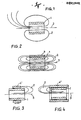
- FIG. 1 which only comprises a cylindrical choke coil 1, it can be seen that the magnetic field 2 spreads radially far with respect to the winding axis 3.
- the choke coil 1 is surrounded by an iron body 4 in the form of a jacket.
- FIG. 2 clearly shows that the radial scattering of the magnetic field can be completely avoided in this way by the tube being guided in the form of a tube and thus no magnetic field can occur radially outside the iron jacket. With this, such chokes be arranged compactly with respect to other components of an electrical circuit, without risk of influencing them.
- the jacket-shaped iron body 4 can consist in the usual way of a wound dynamo sheet or of layered sheet metal lamellae.
- the jacket-shaped iron body can consist of special iron-containing materials, such as ferrite core elements.
- the jacket-shaped iron body 4 consists of at least two shell-shaped parts which can then be attached to the side of the coil body and suitably fastened, for example by means of pipe clamps or the like.
- the axial extent of the magnetic litter can also be expanded move the field and further change the inductive resistance if, in a further embodiment of the choke according to the invention, the jacket-shaped iron body 4 'according to FIG. 3 is slidably seated on the jacket of the choke coil 1, which is not shown in more detail here.
Landscapes
- Engineering & Computer Science (AREA)
- Power Engineering (AREA)
- Microelectronics & Electronic Packaging (AREA)
- Coils Or Transformers For Communication (AREA)
Applications Claiming Priority (2)
| Application Number | Priority Date | Filing Date | Title |
|---|---|---|---|
| CH196385A CH668662A5 (de) | 1985-05-09 | 1985-05-09 | Elektromagnetische drossel. |
| CH1963/85 | 1985-05-09 |
Publications (1)
| Publication Number | Publication Date |
|---|---|
| EP0201846A1 true EP0201846A1 (fr) | 1986-11-20 |
Family
ID=4222701
Family Applications (1)
| Application Number | Title | Priority Date | Filing Date |
|---|---|---|---|
| EP19860106175 Withdrawn EP0201846A1 (fr) | 1985-05-09 | 1986-05-06 | Bobine d'inductance électromagnétique |
Country Status (2)
| Country | Link |
|---|---|
| EP (1) | EP0201846A1 (fr) |
| CH (1) | CH668662A5 (fr) |
Cited By (2)
| Publication number | Priority date | Publication date | Assignee | Title |
|---|---|---|---|---|
| WO2020239849A1 (fr) * | 2019-05-29 | 2020-12-03 | Philip Morris Products S.A. | Composant inductif et procédé de réglage d'une inductance |
| RU2809063C2 (ru) * | 2019-05-29 | 2023-12-06 | Филип Моррис Продактс С.А. | Индуктивный компонент и способ регулировки индуктивности |
Citations (3)
| Publication number | Priority date | Publication date | Assignee | Title |
|---|---|---|---|---|
| AT183841B (de) * | 1953-12-16 | 1955-11-25 | Alfred Rabl | Drossel |
| AT304690B (de) * | 1970-02-05 | 1973-01-25 | Zumtobel Walter | Transformator oder Induktionsspule |
| AT322691B (de) * | 1972-05-31 | 1975-06-10 | Siemens Ag | Elektrische drosselspule |
-
1985
- 1985-05-09 CH CH196385A patent/CH668662A5/de not_active IP Right Cessation
-
1986
- 1986-05-06 EP EP19860106175 patent/EP0201846A1/fr not_active Withdrawn
Patent Citations (3)
| Publication number | Priority date | Publication date | Assignee | Title |
|---|---|---|---|---|
| AT183841B (de) * | 1953-12-16 | 1955-11-25 | Alfred Rabl | Drossel |
| AT304690B (de) * | 1970-02-05 | 1973-01-25 | Zumtobel Walter | Transformator oder Induktionsspule |
| AT322691B (de) * | 1972-05-31 | 1975-06-10 | Siemens Ag | Elektrische drosselspule |
Cited By (6)
| Publication number | Priority date | Publication date | Assignee | Title |
|---|---|---|---|---|
| WO2020239849A1 (fr) * | 2019-05-29 | 2020-12-03 | Philip Morris Products S.A. | Composant inductif et procédé de réglage d'une inductance |
| CN113874968A (zh) * | 2019-05-29 | 2021-12-31 | 菲利普莫里斯生产公司 | 电感部件和用于调整电感的方法 |
| US20220223339A1 (en) * | 2019-05-29 | 2022-07-14 | Philip Morris Products S.A. | Inductive component and method for adjusting an inductance |
| JP2022534579A (ja) * | 2019-05-29 | 2022-08-02 | フィリップ・モーリス・プロダクツ・ソシエテ・アノニム | 誘導構成要素、およびインダクタンスを調整する方法 |
| RU2809063C2 (ru) * | 2019-05-29 | 2023-12-06 | Филип Моррис Продактс С.А. | Индуктивный компонент и способ регулировки индуктивности |
| US12315671B2 (en) * | 2019-05-29 | 2025-05-27 | Philip Morris Products S.A. | Inductive component and method for adjusting an inductance |
Also Published As
| Publication number | Publication date |
|---|---|
| CH668662A5 (de) | 1989-01-13 |
Similar Documents
| Publication | Publication Date | Title |
|---|---|---|
| DE10260246B4 (de) | Spulenanordnung mit veränderbarer Induktivität | |
| EP2614510B1 (fr) | Bobine compensée en courant ayant une inductance de fuite améliorée | |
| DE10225409B4 (de) | Stromkompensierte Drossel und Schaltungsanordnung mit der stromkompensierten Drossel | |
| EP2546842A2 (fr) | Bobine destinée à la limitation du courant | |
| DE69402403T2 (de) | Spule zur Linearitätskorrektur | |
| DE1270074B (de) | Einrichtung zum Entmagnetisieren von Farbbildroehren | |
| DE102005008302B4 (de) | Transformatorkern mit magnetischer Abschirmung | |
| EP0201846A1 (fr) | Bobine d'inductance électromagnétique | |
| DE3621573C2 (de) | Stromkompensierte Funkentstördrossel | |
| DE3417357A1 (de) | Elektromagnetische vorrichtung | |
| DE10051433A1 (de) | Ventilspule für ein Ventilsteuergerät | |
| DE202005008726U1 (de) | Transformator | |
| EP0275499A1 (fr) | Bobine de réactance à courant compensé pour suppression d'interférence d'étincelle | |
| DE4320714A1 (de) | Dioden-Split-Hochspannungstransformator | |
| DE2426255C3 (de) | Spulenanordnung für eine elektrische Induktionseinrichtung | |
| AT152171B (de) | Regeltransformator. | |
| AT310868B (de) | Geräuscharme Starkstrom-Tauchkernspule, insbesondere für Erdschlußlöschung | |
| DE3927235C2 (fr) | ||
| DE3744436C2 (fr) | ||
| EP0602528A1 (fr) | Transformateur | |
| DE3139905C2 (de) | Verfahren zum Betrieb einer Elektronenlinse mit drei Magnetpolstücken | |
| DE2256322C3 (de) | Stabkerndrossel zur Entstörung von Phasenanschnittschaltungen | |
| AT141432B (de) | Vorrichtung zur Regelung der Stromstärke und Spannung von Ein- und Mehrphasentransformatoren. | |
| DE2446583B2 (de) | Abgleichbare, abgeschirmte elektrische spule | |
| DE102015107294A1 (de) | Spulenanordnung für Spannungsregler |
Legal Events
| Date | Code | Title | Description |
|---|---|---|---|
| PUAI | Public reference made under article 153(3) epc to a published international application that has entered the european phase |
Free format text: ORIGINAL CODE: 0009012 |
|
| AK | Designated contracting states |
Kind code of ref document: A1 Designated state(s): AT DE FR GB |
|
| 17P | Request for examination filed |
Effective date: 19870427 |
|
| 17Q | First examination report despatched |
Effective date: 19880530 |
|
| STAA | Information on the status of an ep patent application or granted ep patent |
Free format text: STATUS: THE APPLICATION IS DEEMED TO BE WITHDRAWN |
|
| 18D | Application deemed to be withdrawn |
Effective date: 19890905 |