EP0201854B1 - Ringlaserwinkelgeschwindigkeitsmessvorrichtung - Google Patents
Ringlaserwinkelgeschwindigkeitsmessvorrichtung Download PDFInfo
- Publication number
- EP0201854B1 EP0201854B1 EP86106211A EP86106211A EP0201854B1 EP 0201854 B1 EP0201854 B1 EP 0201854B1 EP 86106211 A EP86106211 A EP 86106211A EP 86106211 A EP86106211 A EP 86106211A EP 0201854 B1 EP0201854 B1 EP 0201854B1
- Authority
- EP
- European Patent Office
- Prior art keywords
- block
- substrate
- sensor according
- cavity
- mirrors
- Prior art date
- Legal status (The legal status is an assumption and is not a legal conclusion. Google has not performed a legal analysis and makes no representation as to the accuracy of the status listed.)
- Expired
Links
- 239000000758 substrate Substances 0.000 claims description 18
- 239000011248 coating agent Substances 0.000 claims description 9
- 238000000576 coating method Methods 0.000 claims description 9
- 239000013078 crystal Substances 0.000 claims description 4
- XAGFODPZIPBFFR-UHFFFAOYSA-N aluminium Chemical compound [Al] XAGFODPZIPBFFR-UHFFFAOYSA-N 0.000 claims description 2
- 229910052782 aluminium Inorganic materials 0.000 claims description 2
- 239000005388 borosilicate glass Substances 0.000 claims 1
- 230000008878 coupling Effects 0.000 claims 1
- 238000010168 coupling process Methods 0.000 claims 1
- 238000005859 coupling reaction Methods 0.000 claims 1
- 238000010276 construction Methods 0.000 description 7
- 235000012431 wafers Nutrition 0.000 description 7
- 239000007789 gas Substances 0.000 description 5
- 238000002789 length control Methods 0.000 description 5
- 239000000463 material Substances 0.000 description 4
- 238000000034 method Methods 0.000 description 4
- 239000007787 solid Substances 0.000 description 4
- 239000011521 glass Substances 0.000 description 3
- 230000003287 optical effect Effects 0.000 description 3
- 239000004593 Epoxy Substances 0.000 description 2
- VYPSYNLAJGMNEJ-UHFFFAOYSA-N Silicium dioxide Chemical compound O=[Si]=O VYPSYNLAJGMNEJ-UHFFFAOYSA-N 0.000 description 2
- GWEVSGVZZGPLCZ-UHFFFAOYSA-N Titan oxide Chemical compound O=[Ti]=O GWEVSGVZZGPLCZ-UHFFFAOYSA-N 0.000 description 2
- 230000007423 decrease Effects 0.000 description 2
- 239000000203 mixture Substances 0.000 description 2
- 229910000640 Fe alloy Inorganic materials 0.000 description 1
- 229910001374 Invar Inorganic materials 0.000 description 1
- 230000001419 dependent effect Effects 0.000 description 1
- 230000000694 effects Effects 0.000 description 1
- 230000005684 electric field Effects 0.000 description 1
- 229920006335 epoxy glue Polymers 0.000 description 1
- CPBQJMYROZQQJC-UHFFFAOYSA-N helium neon Chemical compound [He].[Ne] CPBQJMYROZQQJC-UHFFFAOYSA-N 0.000 description 1
- XEEYBQQBJWHFJM-UHFFFAOYSA-N iron Substances [Fe] XEEYBQQBJWHFJM-UHFFFAOYSA-N 0.000 description 1
- 238000004519 manufacturing process Methods 0.000 description 1
- 238000007789 sealing Methods 0.000 description 1
- 239000005368 silicate glass Substances 0.000 description 1
- 235000012239 silicon dioxide Nutrition 0.000 description 1
- 239000000377 silicon dioxide Substances 0.000 description 1
- 239000004408 titanium dioxide Substances 0.000 description 1
Images
Classifications
-
- H—ELECTRICITY
- H01—ELECTRIC ELEMENTS
- H01S—DEVICES USING THE PROCESS OF LIGHT AMPLIFICATION BY STIMULATED EMISSION OF RADIATION [LASER] TO AMPLIFY OR GENERATE LIGHT; DEVICES USING STIMULATED EMISSION OF ELECTROMAGNETIC RADIATION IN WAVE RANGES OTHER THAN OPTICAL
- H01S3/00—Lasers, i.e. devices using stimulated emission of electromagnetic radiation in the infrared, visible or ultraviolet wave range
- H01S3/02—Constructional details
- H01S3/03—Constructional details of gas laser discharge tubes
- H01S3/034—Optical devices within, or forming part of, the tube, e.g. windows, mirrors
-
- G—PHYSICS
- G01—MEASURING; TESTING
- G01C—MEASURING DISTANCES, LEVELS OR BEARINGS; SURVEYING; NAVIGATION; GYROSCOPIC INSTRUMENTS; PHOTOGRAMMETRY OR VIDEOGRAMMETRY
- G01C19/00—Gyroscopes; Turn-sensitive devices using vibrating masses; Turn-sensitive devices without moving masses; Measuring angular rate using gyroscopic effects
- G01C19/58—Turn-sensitive devices without moving masses
- G01C19/64—Gyrometers using the Sagnac effect, i.e. rotation-induced shifts between counter-rotating electromagnetic beams
- G01C19/66—Ring laser gyrometers
- G01C19/661—Ring laser gyrometers details
- G01C19/665—Ring laser gyrometers details control of the cavity
-
- H—ELECTRICITY
- H01—ELECTRIC ELEMENTS
- H01S—DEVICES USING THE PROCESS OF LIGHT AMPLIFICATION BY STIMULATED EMISSION OF RADIATION [LASER] TO AMPLIFY OR GENERATE LIGHT; DEVICES USING STIMULATED EMISSION OF ELECTROMAGNETIC RADIATION IN WAVE RANGES OTHER THAN OPTICAL
- H01S3/00—Lasers, i.e. devices using stimulated emission of electromagnetic radiation in the infrared, visible or ultraviolet wave range
- H01S3/05—Construction or shape of optical resonators; Accommodation of active medium therein; Shape of active medium
- H01S3/08—Construction or shape of optical resonators or components thereof
- H01S3/081—Construction or shape of optical resonators or components thereof comprising three or more reflectors
- H01S3/083—Ring lasers
- H01S3/0835—Gas ring lasers
Definitions
- the present invention relates to a ring laser angular rate sensor according to the preamble of claim 1.
- ring laser angular rate sensors commonly referred to as ring laser gyros
- ring laser gyros have become commercially successful products and are rapidly replacing conventional mechanical angular rate sensors in many applications.
- Today, most commercial ring laser angular rate sensors use a mechanically and thermally stable block construction and mechanical dither concepts taught in U.S. Patent Numbers 3,390,606; 3,467,472; and 3,373,650.
- US-A-3,390,606 the mirrors are bonded by means of optical contact and a suitable epoxy glue.
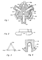
- a silicate glass block 10 more particularly a borosilicate, preferably BK-7 (letter number combinations are Schott Optical commercial designations), has bores 12a, 12b, and 12c machined therein to form a triangular lasing cavity.
- Mirrors 14ac; 14ab; and 14bc are attached to the block at the intersections of the paths 12. It will be appreciated that ring laser angular rate sensors with a rectangular lasing cavity or other cavity configurations, including a cubic. cavity, can be constructed in accordance with the teaching of this invention.
- mirror 14ac is partially transmissive for providing a readout beam signal
- mirror 14ab is curved and focuses the counter-rotating laser beams, and mirror 14bc controls the cavity path length.
- a sensor 15 attached to mirror 14ab provides path length control signals to mirror 14bc as in prior art ring laser angular rate sensors.
- An anode 16 and a pair of cathodes 18 and 20 are fixed to the block 10 and will be described in greater detail in connection with Figure 4. As will be appreciated by those skilled in the art, these electrodes couple electrical energy into a gas which fills the cavities and generates the counter-rotating laser beams.
- cylindrical passages 22a, 22b, and 22c machined into the block 10 where the cathodes and anode are attached to the block. These passages allow the lasing gas to communicate with the interior surfaces of the cathodes and anode.
- the bores 22a, 22b, and 22c extend into the block beyond the paths in order to provide reservoirs to increase the total gas volume of the system.
- the construction of the ring laser angular rate sensor in accordance with the teaching of the invention is novel, its basic operating principle is the same as those of prior art ring laser angular rate sensors.
- the cavities within the block 10 are filled with a lasing gas of helium neon mixture.
- An electric field between the anode 16 and the cathodes 18 and 20 establishes counter-rotating laser beams within the passages 12 in the block 10.
- Rotation of the block 10 causes the frequency of one of the counter-rotating beams to increase, and the other to decrease.
- the frequency difference is detected by a suitable sensor mounted to mirror 14ac.
- the photodetector output signals are procesed in a suitable manner well understood by those skilled in the art.
- the ring laser angular rate sensor block 10 is a solid block of BK-7 glass into which the lasing paths are machined, as previously explained.
- a substrate 21 for each mirror is also formed from BK-7 glass.
- a laser reflective coating 24 is formed on the surface of the substrate 22 in a suitable manner known to those skilled in the art.
- a coating comprised of a layer of titanium dioxide and a layer of silicon dioxide is suitable.
- the choice of material for the solid block 10, the substrate 21, and the coating 24 is dictated by the need to have compatible coefficients of expansion for the solid block 10, the substrate 21, and the coating 24.
- a thermally formed frit sealing process can be used to join the substrate 22 to block 10.
- the frit seal is formed with a soldered glass or frit material 26 in a process in which temperatures are raised to the range of 450°-500°C for a substantial period of time, emphasizing the need for each of the parts to have a compatible temperature coefficient of expansion.
- flat mirrors 14bc and 14ac, and a curved mirror 14ab circulate the counter-rotating beams in the cavity formed by the passages 12ab, 12ac, and 12bc machined into the block 10.
- the cavity confines the laser beam, stabilizes it against angular distortion of the block, and forces the laser to oscillate in a singular transverse mode.
- the diameter of the laser gain fuse should be chosen as to provide gain and intercavity aperture to discriminate against off-access modes. A gain tube diameter of 0.030 inches (0,762 mm) has proven satisfactory.
- a ring laser angular rate sensor constructed in accordance with the teaching of this invention have a short cavity. Applicants have determined that a cavity of approximately 2.4 inches (5,99 cm) is satisfactory. A cavity in excess of six inches (15,24 cm) in length would ordinarily be impractical.
- the focussing mirror 14ab has a curved reflecting surface with a short radius of curvature. As the radius of curvature of the mirror 14ab decreases, the amount of misalignment in the cavity which can be tolerated increases to a limit where the radius equals the path length. Beyond this, i.e., radius less than the cavity length, the lasing beams become unstable.
- the radius of curvature of mirror 14ab is 15 cm to 20 cm with a cavity length of about 6 cm.
- the radius can vary as the cavity length varies with the range of an inner limit equal to the path length and an outer limit of six times the path length.
- the electrodes provide an electrical connection to the laser gas.
- Each of the electrodes, one anode and two cathodes, is made to match the thermal coefficient of expansion of the block 10. This enables the use of a thermal bonding process to affix the electrodes to the block 10 and provide a hermetic seal 36 there between.
- a base 32 made from nickle-iron alloy and its intersurface is coated with a thin layer of aluminum 34.
- the ratio of Ni to Fe can be adjusted so that this Invar type material has a thermal coefficient of expansion which is compatible with the thermal coefficient of the block 10.
- a mixture of about Ni-49%, Fe-50% and 1% materials to improve machinery, etc. is satisfactory.
- the walls of the electrodes should be thin to provide flexibility where the electrode is attached to the block 10. This construction compensates for any relative movement between the block and the electrode due to thermally or mechanically induced stress.
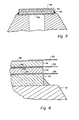
- a path length control mirror maintains the length of the cavity at an integral number of wave lengths in accordance with the techniques known to those skilled in the art.
- the construction of the path length control mirror shown in Figure 5 is novel and advantageous as it is dramatically simple and more straightforward than those employed in the prior art.
- the novel path length control comprises a substrate 42 with reflective coating 24 affixed to the block 10 all in the manner described in connection with Figure 2 with a BK-7 block 10 and a BK-7 substrate 42.
- the substrate 42 is relatively thin e.g., 0.020 inches (0,5 mm) thick, in a preferred embodiment.
- Bonded to the mirror substrate 42 are two piezoelectric wafers 44 and 46.
- the orientation of the wafers 44 and 46 relative to one another is such as to cancel the effect of temperature changes.
- Each of the wafers are preferably 1/2 the thickness of the mirror substrate.
- a conductive electrode 48 is deposited over the entire upper and lower surface of each of the piezoelectric wafers 44 and 46.
- the lower wafer 44 is bonded to mirror substrate 42 with a suitable epoxy, and similarly the upper wafer 46 is epoxy bonded to the lower wafer 44.
- Conductive tabs 52 are attached to the electrode surfaces and permitted appropriate signals to be coupled to the piezoelectric crystals in order to deflect the mirror substrate and thus alter the path length so that the path length is an integral number of wavelengths.
Landscapes
- Physics & Mathematics (AREA)
- Engineering & Computer Science (AREA)
- Electromagnetism (AREA)
- Optics & Photonics (AREA)
- Plasma & Fusion (AREA)
- Power Engineering (AREA)
- General Physics & Mathematics (AREA)
- Radar, Positioning & Navigation (AREA)
- Remote Sensing (AREA)
- Gyroscopes (AREA)
- Lasers (AREA)
Claims (8)
Applications Claiming Priority (2)
| Application Number | Priority Date | Filing Date | Title |
|---|---|---|---|
| US06/733,279 US4817112A (en) | 1985-05-10 | 1985-05-10 | Low cost ring laser angular rate sensor |
| US733279 | 1985-05-10 |
Publications (3)
| Publication Number | Publication Date |
|---|---|
| EP0201854A2 EP0201854A2 (de) | 1986-11-20 |
| EP0201854A3 EP0201854A3 (en) | 1988-07-20 |
| EP0201854B1 true EP0201854B1 (de) | 1990-12-05 |
Family
ID=24946949
Family Applications (1)
| Application Number | Title | Priority Date | Filing Date |
|---|---|---|---|
| EP86106211A Expired EP0201854B1 (de) | 1985-05-10 | 1986-05-06 | Ringlaserwinkelgeschwindigkeitsmessvorrichtung |
Country Status (7)
| Country | Link |
|---|---|
| US (1) | US4817112A (de) |
| EP (1) | EP0201854B1 (de) |
| JP (1) | JPH0691291B2 (de) |
| CN (1) | CN86103124A (de) |
| CA (1) | CA1243764A (de) |
| DE (1) | DE3675978D1 (de) |
| IL (1) | IL78397A (de) |
Families Citing this family (12)
| Publication number | Priority date | Publication date | Assignee | Title |
|---|---|---|---|---|
| CA1293793C (en) * | 1986-03-25 | 1991-12-31 | Hans P. Meyerhoff | Low cost ring laser angular rate sensor |
| GB8728829D0 (en) * | 1987-12-10 | 1988-01-27 | British Aerospace | Ring laser gyroscopes |
| US5197653A (en) * | 1992-03-27 | 1993-03-30 | Honeywell Inc. | Method of sealing two articles together with an indium preform seal |
| GB2265752B (en) * | 1992-03-31 | 1995-07-05 | British Aerospace | A lasing apparatus |
| US5517306A (en) * | 1994-06-15 | 1996-05-14 | Yakubovich; Evsey | Method and apparatus for measuring angular velocity of a transparent object |
| US6406578B1 (en) * | 1999-10-19 | 2002-06-18 | Honeywell Inc. | Seal and method of making same for gas laser |
| US8071019B2 (en) * | 2008-10-31 | 2011-12-06 | Honeywell International Inc. | Methods for introduction of a reactive material into a vacuum chamber |
| US8854146B2 (en) * | 2012-01-31 | 2014-10-07 | Honeywell International Inc. | Systems and methods for external frit mounted components |
| US8526000B1 (en) | 2012-05-29 | 2013-09-03 | Honeywell International Inc. | Atomic sensor physics package with integrated transmissive and reflective portions along light paths |
| US9285249B2 (en) | 2012-10-04 | 2016-03-15 | Honeywell International Inc. | Atomic sensor physics package with metal frame |
| US9410885B2 (en) | 2013-07-22 | 2016-08-09 | Honeywell International Inc. | Atomic sensor physics package having optically transparent panes and external wedges |
| CN114289872B (zh) * | 2022-03-07 | 2022-08-23 | 西安中科华芯测控有限公司 | 一种微型激光陀螺用超快激光反射镜的装配方法 |
Family Cites Families (21)
| Publication number | Priority date | Publication date | Assignee | Title |
|---|---|---|---|---|
| US3390606A (en) * | 1965-03-01 | 1968-07-02 | Honeywell Inc | Control apparatus |
| US3904986A (en) * | 1974-04-19 | 1975-09-09 | Rca Corp | Gas laser tube |
| US4007431A (en) * | 1975-02-03 | 1976-02-08 | Litton Systems, Inc. | Cathode construction for long life lasers |
| US4233568A (en) * | 1975-02-24 | 1980-11-11 | Xerox Corporation | Laser tube mirror assembly |
| US3997385A (en) * | 1975-08-18 | 1976-12-14 | W. R. Grace & Co. | Clamping of film-like material for radiant energy welding |
| US4203080A (en) * | 1976-05-24 | 1980-05-13 | Spectra Physics, Inc. | Method and apparatus for producing laser plasma tube and product |
| US4063803A (en) * | 1976-06-03 | 1977-12-20 | Spectra-Physics, Inc. | Transmissive end seal for laser tubes |
| US4153317A (en) * | 1977-12-02 | 1979-05-08 | The Singer Company | Indium seal for gas laser |
| US4142958A (en) * | 1978-04-13 | 1979-03-06 | Litton Systems, Inc. | Method for fabricating multi-layer optical films |
| US4383763A (en) * | 1979-09-12 | 1983-05-17 | Litton Systems, Inc. | Controllable mirrors |
| US4561780A (en) * | 1980-04-28 | 1985-12-31 | The Singer Company | Pathlength controller for ring laser gyroscope |
| US4352185A (en) * | 1980-07-18 | 1982-09-28 | Uniphase Corporation | Gas laser having improved stability against environmental conditions |
| US4392229A (en) * | 1980-12-15 | 1983-07-05 | Litton Systems, Inc. | Ring laser with plasma starter |
| US4525028A (en) * | 1981-04-23 | 1985-06-25 | Raytheon Company | Enhanced magnetic mirror |
| US4554667A (en) * | 1981-04-23 | 1985-11-19 | United Technologies Corporation | Sealed-off CO2 laser |
| US4410274A (en) * | 1981-06-08 | 1983-10-18 | The Singer Company | Ring laser gyroscope with doppler mirrors and offset actuators |
| JPS5910078A (ja) * | 1982-07-08 | 1984-01-19 | Konishiroku Photo Ind Co Ltd | テレビカメラ用レンズ鏡胴 |
| GB2126776B (en) * | 1982-08-26 | 1985-12-04 | British Aerospace | Ring laser gyroscopes |
| US4612647A (en) * | 1982-12-27 | 1986-09-16 | Litton Systems, Inc. | High performance laser and method of making same |
| AU3997785A (en) * | 1984-02-08 | 1985-08-27 | Sundstrand Optical Technologies Inc. | Ring laser gyro tilt mirror dither |
| US4595377A (en) * | 1984-12-10 | 1986-06-17 | Rockwell International Corporation | Cold cathode fabrication for ring laser gyroscope |
-
1985
- 1985-05-10 US US06/733,279 patent/US4817112A/en not_active Expired - Lifetime
-
1986
- 1986-03-31 IL IL78397A patent/IL78397A/xx unknown
- 1986-04-21 CA CA000507100A patent/CA1243764A/en not_active Expired
- 1986-05-05 CN CN198686103124A patent/CN86103124A/zh active Pending
- 1986-05-06 EP EP86106211A patent/EP0201854B1/de not_active Expired
- 1986-05-06 DE DE8686106211T patent/DE3675978D1/de not_active Expired - Lifetime
- 1986-05-09 JP JP61105020A patent/JPH0691291B2/ja not_active Expired - Lifetime
Also Published As
| Publication number | Publication date |
|---|---|
| CN86103124A (zh) | 1986-11-26 |
| US4817112A (en) | 1989-03-28 |
| CA1243764A (en) | 1988-10-25 |
| JPH0691291B2 (ja) | 1994-11-14 |
| DE3675978D1 (de) | 1991-01-17 |
| EP0201854A3 (en) | 1988-07-20 |
| EP0201854A2 (de) | 1986-11-20 |
| JPS61263293A (ja) | 1986-11-21 |
| IL78397A (en) | 1990-02-09 |
Similar Documents
| Publication | Publication Date | Title |
|---|---|---|
| EP0201854B1 (de) | Ringlaserwinkelgeschwindigkeitsmessvorrichtung | |
| US3555450A (en) | Laser window having a metallic frame arranged to permit post optical grinding and polishing | |
| US4797896A (en) | Solid state optical ring resonator and laser using same | |
| US4035081A (en) | Laser gyroscope | |
| US20030010420A1 (en) | Monolithic ceramic laser structure and method of making same | |
| EP0251128B1 (de) | Verfahren zur Herstellung eines Ringlasers | |
| EP0339543A2 (de) | Piezoelektrisch abgestimmter optischer Resonator und Laser, der diesen verwendet | |
| US3982204A (en) | Laser discharge tube assembly | |
| US5334901A (en) | Vibrating beam accelerometer | |
| US3889207A (en) | Frequency stabilized gas laser | |
| US4865436A (en) | Low cost ring laser angular rate sensor | |
| US4973161A (en) | Ring laser gyroscopes | |
| US5056920A (en) | Low cost ring laser angular rate sensor including thin fiber glass bonding of components to a laser block | |
| US4565941A (en) | Oscillatory drive mechanisms for a ring laser gyro | |
| WO1986001887A1 (en) | Stable path length control elements | |
| EP0021419B1 (de) | Vibrierender Laserkreisel | |
| US5420685A (en) | Electrostatic path length control transducer | |
| JPH0624269B2 (ja) | Tea炭酸ガスレーザ装置 | |
| US4848909A (en) | Ion beam sputtered mirrors for ring laser gyros | |
| EP0239032B1 (de) | Gasentladungsvorrichtung und Methode zu ihrer Herstellung | |
| US3936768A (en) | Molecular gas laser device with an improved output mirror means | |
| WO1988002103A1 (en) | Low cost ring laser angular rate sensor | |
| JPH0371683A (ja) | 気体レーザ装置 | |
| RU2096880C1 (ru) | Газовый лазер | |
| JPS6324688A (ja) | レ−ザブロツク組立体 |
Legal Events
| Date | Code | Title | Description |
|---|---|---|---|
| PUAI | Public reference made under article 153(3) epc to a published international application that has entered the european phase |
Free format text: ORIGINAL CODE: 0009012 |
|
| AK | Designated contracting states |
Kind code of ref document: A2 Designated state(s): DE FR GB SE |
|
| PUAL | Search report despatched |
Free format text: ORIGINAL CODE: 0009013 |
|
| AK | Designated contracting states |
Kind code of ref document: A3 Designated state(s): DE FR GB SE |
|
| 17P | Request for examination filed |
Effective date: 19890105 |
|
| 17Q | First examination report despatched |
Effective date: 19900514 |
|
| GRAA | (expected) grant |
Free format text: ORIGINAL CODE: 0009210 |
|
| AK | Designated contracting states |
Kind code of ref document: B1 Designated state(s): DE FR GB SE |
|
| ET | Fr: translation filed | ||
| REF | Corresponds to: |
Ref document number: 3675978 Country of ref document: DE Date of ref document: 19910117 |
|
| PLBE | No opposition filed within time limit |
Free format text: ORIGINAL CODE: 0009261 |
|
| STAA | Information on the status of an ep patent application or granted ep patent |
Free format text: STATUS: NO OPPOSITION FILED WITHIN TIME LIMIT |
|
| 26N | No opposition filed | ||
| EAL | Se: european patent in force in sweden |
Ref document number: 86106211.5 |
|
| REG | Reference to a national code |
Ref country code: GB Ref legal event code: IF02 |
|
| PGFP | Annual fee paid to national office [announced via postgrant information from national office to epo] |
Ref country code: GB Payment date: 20050406 Year of fee payment: 20 |
|
| PGFP | Annual fee paid to national office [announced via postgrant information from national office to epo] |
Ref country code: SE Payment date: 20050503 Year of fee payment: 20 |
|
| PGFP | Annual fee paid to national office [announced via postgrant information from national office to epo] |
Ref country code: FR Payment date: 20050517 Year of fee payment: 20 |
|
| PGFP | Annual fee paid to national office [announced via postgrant information from national office to epo] |
Ref country code: DE Payment date: 20050531 Year of fee payment: 20 |
|
| PG25 | Lapsed in a contracting state [announced via postgrant information from national office to epo] |
Ref country code: GB Free format text: LAPSE BECAUSE OF EXPIRATION OF PROTECTION Effective date: 20060505 |
|
| REG | Reference to a national code |
Ref country code: GB Ref legal event code: PE20 |
|
| EUG | Se: european patent has lapsed | ||
| P01 | Opt-out of the competence of the unified patent court (upc) registered |
Effective date: 20230525 |