EP0201857A2 - Dispositif d'éclairage basse tension - Google Patents
Dispositif d'éclairage basse tension Download PDFInfo
- Publication number
- EP0201857A2 EP0201857A2 EP86106218A EP86106218A EP0201857A2 EP 0201857 A2 EP0201857 A2 EP 0201857A2 EP 86106218 A EP86106218 A EP 86106218A EP 86106218 A EP86106218 A EP 86106218A EP 0201857 A2 EP0201857 A2 EP 0201857A2
- Authority
- EP
- European Patent Office
- Prior art keywords
- plug
- rails
- rail
- low
- lighting arrangement
- Prior art date
- Legal status (The legal status is an assumption and is not a legal conclusion. Google has not performed a legal analysis and makes no representation as to the accuracy of the status listed.)
- Ceased
Links
Images


Classifications
-
- H—ELECTRICITY
- H01—ELECTRIC ELEMENTS
- H01R—ELECTRICALLY-CONDUCTIVE CONNECTIONS; STRUCTURAL ASSOCIATIONS OF A PLURALITY OF MUTUALLY-INSULATED ELECTRICAL CONNECTING ELEMENTS; COUPLING DEVICES; CURRENT COLLECTORS
- H01R25/00—Coupling parts adapted for simultaneous co-operation with two or more identical counterparts, e.g. for distributing energy to two or more circuits
- H01R25/14—Rails or bus-bars constructed so that the counterparts can be connected thereto at any point along their length
- H01R25/147—Low voltage devices, i.e. safe to touch live conductors
-
- H—ELECTRICITY
- H01—ELECTRIC ELEMENTS
- H01R—ELECTRICALLY-CONDUCTIVE CONNECTIONS; STRUCTURAL ASSOCIATIONS OF A PLURALITY OF MUTUALLY-INSULATED ELECTRICAL CONNECTING ELEMENTS; COUPLING DEVICES; CURRENT COLLECTORS
- H01R2201/00—Connectors or connections adapted for particular applications
- H01R2201/08—Connectors or connections adapted for particular applications for halogen lamps
Definitions
- the invention relates to a low-voltage lighting arrangement with longitudinally stringable, cross-sectionally U-shaped current extraction rails, in which the current extraction rails are provided in the plug-in receptacles formed by their side legs and the central web with two contact rails, in which the contact rails of adjacent current extraction rails can be electrically connected by means of connectors and in which the connector and other connection units, such as lamp units, power supply unit, connecting plug, can be plugged into the plug-in receptacles of the power take-off rails and locked therein.
- Such low voltage lighting arrangements are expandable and adaptable to the devices to be illuminated, such as. B. DE-OSn 24 15 009 and 30 25 913 show.
- DE-OSn 24 15 009 and 30 25 913 show.
- connection units such as DE-PS 21 06 422 and DE-OS 29 08 728 show.
- connection units It is common to all these known lighting arrangements that the plug-in direction of the connection units is perpendicular to the fastening surface of the current drain rail. This inevitably results in a large overall height, which is e.g. when attaching the lighting arrangement to the underside of wall cabinets, e.g. of kitchen wall cabinets, as disadvantageous - because disruptive.
- a side leg of the power take-off rails is designed as a mounting leg with fastening receptacles, that the connection units, such as lighting units, power supply unit, connecting plug and connector, have a box-like shape and that the connecting devices inserted into the plug-in receptacles of the power take-off rails are perpendicular to the associated one Fastening legs have a dimension that corresponds approximately to the distance between the outer sides of the side legs of the current drain rails.
- the attachment of the current drain rails to the fastening surface is facilitated in one embodiment in that the side leg with the fastening receptacles projects beyond the other side leg of the current drain rail and that the fastening receptacles are introduced in the part of the one side leg protruding above the other side leg.
- the mounting receptacles can easily be designed so that the mounting screws do not protrude into the plug receptacle of the current drain rail and therefore do not interfere with the insertion of the connection units.
- An embodiment is advantageous, which is characterized by the fact that the contact rails are attached to the inside of the footbridge of the power take-off rail and are arranged symmetrically to the center plane of the plug receptacle, since then small connection units, such as connectors or plugs, can also be rotated in two positions in 180 ° the plug-in receptacle of the .current-taking rail can be inserted and locked therein.
- connection units on the current extraction rail when the contacts and the locking elements are relieved is improved in one embodiment in that the side leg of the current extraction rail forming the fastening leg has a holding flange at the free end which is set back against the outside of the fastening leg and is flush with the inside thereof. and that the connection units are provided with a receiving groove receiving the holding flange. If the connection unit can be inserted into the plug receptacle of the current drain rail in two positions rotated by 180 °, then the connection unit carries two receiving grooves for the retaining web of the current drain rail.
- connection units in the plug receptacle of the busbar For simple locking of the connection units in the plug receptacle of the busbar, one embodiment provides that the mutually facing inner sides of the side legs the power take-off rail are provided with mutually aligned, projecting locking webs, and that the connection units are provided on the connection side designed as a plug-in part with rotatably mounted locking elements which can be inserted into the plug-in receptacle in an insertion-rotation position between the locking webs and in a locked rotational position behind the Locking bars are held.
- each connection unit has two locking elements which are rotatably mounted in the outer regions of the front plug-in side of the plug-in part, and that between the two locking elements in the plug-in side the connection contacts of the connection unit are guided out and are spring-loaded and held therein .
- connection contacts are designed as U-shaped flat contacts, which are aligned parallel to the mounting leg and protrude from the connection unit with the ends of their contact arms;
- the design - is preferably such that the contacts in the connection units have a distance from one another which corresponds to the distance between the central longitudinal axes of the contact rail attached to the central web of the power take-off rail, and that the contacts are arranged symmetrically to the central axis of the plug side of the plug part, which are parallel runs to the fastening leg of the current drain rail.
- a defined plug position of the connection unit in the plug receptacle of the current drain rail is ensured in that the plug part of the connection unit passes into the connection unit via shoulders, and that the shoulders limit the insertion movement of the connection unit into the plug receptacle of the current take off rail by a stop on the locking bars of the current take off rail .
- connection unit such as e.g. a power supply unit with a transformer sufficient power for a number of lighting units
- the integration in the lighting arrangement and the required support is improved in that the retaining web of the mounting leg of the current drain rail overlaps an opposite side of a mounting plate that is perpendicular to the plug receptacle of the current drain rail Edges of the mounting plate are provided with L-shaped, outwardly open guide webs and that the connection units on the fastening side facing the mounting plate are provided with corresponding L-shaped guide receptacles for these guide webs.
- connection units have the same dimensions in the longitudinal direction of the current extraction rail and that the guide webs and the guide receptacles are set back with respect to the edges of the mounting plate and the connection units perpendicular to the current extraction rail.
- the fastening plate is provided with fastening bores for retractable fastening screws
- the fastening plate can also be connected to the fastening surface, the fastening screws not impairing the pushing of the connection unit onto the fastening plate until it is inserted into the facing plug receptacle of the current drain rail .
- FIG. 1 shows, in the low-voltage lighting arrangement, current extraction rails 10 are strung together in the longitudinal direction in a known manner.
- the mounting surface lies in the plane of the sheet and the connection units are inserted in parallel into the plug receptacle of the current drain rail 10 and locked therein, as will be shown.
- a power supply unit 26 of the usual type can be plugged into the power take-off rail 10 via the connecting cable 25 and the connecting plug 24.
- the lighting units 20 are box-shaped and are plugged in directly at any point on the current extraction rails 10 via a plug-in part 21.
- Each lamp unit 20 can carry a switch 23 in the field 22 adjoining the plug-in part 21.
- the halogen lamp used in the lamp unit 20 is covered by the pane of the lamp unit 20.
- Connector 27 electrically switch through the contact rails of adjacent power take-off rails 10.
- the structure of these connectors 27 differs from that of the connector plug 24 only in the absence of a connection for the connecting cable.
- the connector 27 and the connector 24 are similar to the structure of the plug part 21 of a connection unit and differ only in the dimension in the longitudinal direction of the current drain rails 10 of the connector 24 can be selected in the current drain rail 10.
- the connecting cable 28 connects two connecting plugs 24. This corner connector allows the connection of two rail strands of current drain rails 10 which are at right angles to one another.
- the connecting cable 28 can be of different lengths in order to be able to bridge larger distances and other angles between the rail tracks.
- a power supply unit 30 can also be designed as a flat box-like connection unit and can be connected and locked electrically and mechanically to the facing power take-off rail 10 via the plug part 31. It is crucial for the desired small overall height perpendicular to the mounting surface that all connection units, such as connector plug 27, connector 24, lamp units 20 and power supply unit 30, have an overall height which corresponds to the height of the current extraction rail 10 perpendicular to the mounting surface, i.e. corresponds to the distance between the outer sides of the side legs of the U-shaped current extraction rails 10. The power of the power supply 30 is adapted to a predetermined number of lighting units 20.
- Fig. 2 shows the current drain rail 10 in cross section as it is attached to the mounting surface B.
- the side leg 13 is designed as a fastening leg and carries fastening receptacles 14 designed as bores, which can receive fastening screws sunk.
- the central web 11 connects the two side legs 13 and 17 of the current extraction rail 10 and carries the two contact rails 12 on its inside.
- the contact rails 12 are arranged symmetrically to the central plane of the plug receptacle 19. If the side leg 13 is longer than the side leg 17, then the fastening receptacles 14 are introduced in the protruding part of the side leg 13 in order to achieve the screwing of the current extraction rail 10 onto the fastening surface B.
- the current drain rail 10 is preferably designed as a section of a plastic profile strand. The outside of the central web 11 can be flush with the front of the cabinet when attached to a wall cabinet as a panel.
- each connection unit runs, here e.g. a lamp unit 20, in the plug-in part 21, which can be inserted between the two locking webs 16 and 18 until the paragraphs 55 and 56 limit the insertion movement by abutment on the locking webs 16 and 18, as the section according to FIG. 4 shows Plug side of the plug part 21 are the two contacts 35 and 38, which are supported and held in the connection unit by means of springs 41. In the plugged position, the contacts 35 and 38 are therefore under voltage with the contact rails 12 of the current drain rail 10 in an electrically conductive connection. In the connection unit, the contacts 35 and 38 are wired in accordance with the purpose of the connection unit.
- the side leg 13 of the power take-off rail 10 runs out at the free end into the retaining web 15, which is set back from the outside of the side leg 13 and is flush with the inside thereof.
- the connection unit is connected to the plug part 21 and the paragraph 55 in the receiving groove 34 for the Retaining web 15 of the side leg 13, which is formed by the walls 32 and 33 of the housing of the connection unit. This allows the mechanical hold of the in the power take-off rail 10 inserted connection unit significantly improve, while the contacts and the locking elements are relieved.
- connector 27 and the connector 24 have similar plug parts, with spring-loaded contacts and locking elements are attached.
- the contacts 35 and 38 are designed as U-shaped flat contacts, which are aligned parallel to the mounting leg of the current extraction rail 10. Each contact 35 and 38 thus has two contact arms 36 and 37 or 39 and 40, which form separate contact points with the contact rails 12 of the current take-off rail 10. In the case of the connector 27, these contacts 35 and 38 therefore connect the contact rails 12 of the adjacent current consumption rails 10 when correctly inserted into the plug receptacles 19.
- the two plate-shaped locking elements 42 and 44 are rotatably mounted on the plug side of the plug part 21, as the axes of rotation 43 and 45 lying on the horizontal central axis of the plug part 21 show.
- the locking element 42 is brought into the locked rotational position, in which it engages behind the locking webs 16 and 18 and holds the connection unit on the power take-off rail 10, as can be seen in FIG. 4.
- the locking element 44 is in the insertion rotary position in which it can pass the bottleneck between the two locking webs 16 and 18.
- the two locking elements 42 and 44 lie outside the contacts 35 and 38 in the edge region of the box-like connection unit. A single locking element may also be sufficient for the connector plug 27 and the connector 24.
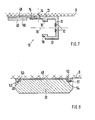
- connection unit e.g. the power supply 30 with the transformer for the low voltage, large area and heavy
- additional attachment shown in FIGS. 7 and 8 is selected with a mounting plate 48.
- the guide web 15 of the side leg 13 engages over the fastening plate 48, which can be screwed to the fastening surface B in a known manner.
- the mounting receptacles are again designed so that the mounting screws are countersunk.
- L-shaped guide webs are formed on the mounting plate 48 at the edges perpendicular to the flow extraction rail 10 and are formed from the sections 49 and 50 or 51 and 52. The guide webs are each open to the outside and set back with respect to the edge of the mounting plate 48.
- connection unit, power supply 30, carries on the underside the two L-shaped guide receptacles 53 and 54, into which the guide webs can be inserted.
- the dimensions in the longitudinal direction of the current drain rail 10 are the same for the mounting plate 48 and the connection unit, so that there is a flush closure.
- the power supply 30 has a correspondingly wide plug-in part 31 that, like the lamp unit 20, is provided with two contacts 35 and 38 and two locking elements 42 and 44.
Landscapes
- Details Of Connecting Devices For Male And Female Coupling (AREA)
- Connector Housings Or Holding Contact Members (AREA)
Applications Claiming Priority (2)
| Application Number | Priority Date | Filing Date | Title |
|---|---|---|---|
| DE19853516449 DE3516449A1 (de) | 1985-05-08 | 1985-05-08 | Niederspannungs-beleuchtungsanordnung |
| DE3516449 | 1985-05-08 |
Publications (2)
| Publication Number | Publication Date |
|---|---|
| EP0201857A2 true EP0201857A2 (fr) | 1986-11-20 |
| EP0201857A3 EP0201857A3 (fr) | 1988-09-21 |
Family
ID=6270077
Family Applications (1)
| Application Number | Title | Priority Date | Filing Date |
|---|---|---|---|
| EP86106218A Ceased EP0201857A3 (fr) | 1985-05-08 | 1986-05-06 | Dispositif d'éclairage basse tension |
Country Status (2)
| Country | Link |
|---|---|
| EP (1) | EP0201857A3 (fr) |
| DE (1) | DE3516449A1 (fr) |
Cited By (1)
| Publication number | Priority date | Publication date | Assignee | Title |
|---|---|---|---|---|
| EP0771999A3 (fr) * | 1995-11-02 | 1998-04-29 | Briloner Leuchten GmbH | Système de rails en très basse tension pour éclairage |
Family Cites Families (8)
| Publication number | Priority date | Publication date | Assignee | Title |
|---|---|---|---|---|
| DE1825183U (de) * | 1960-10-29 | 1961-01-19 | Werner Struthoff | Stromleitungsabschnitt in element der raumausstattung. |
| DE7113440U (de) * | 1971-04-07 | 1971-07-22 | Erco Leuchten Kg | Deckenbefestigung fuer eine elektrische leitungsschiene |
| DE2327078A1 (de) * | 1972-05-29 | 1973-12-13 | Staff Kg | Stromverteilerschiene fuer stromabnehmer, insbesondere adapter |
| DE2415009A1 (de) * | 1974-03-28 | 1975-10-16 | Artur Zimmermann | Elektrische kleinspannungs-installationsschiene |
| IT1062955B (it) * | 1976-05-26 | 1985-02-11 | G C Illumination S P A | Canale elettrificato con connettore ad innesto a scatto |
| DE2908728A1 (de) * | 1979-03-06 | 1980-09-11 | Peter Nawrath | Stromverteilungssystem mit beweglichen einspeise- und entnahmeadaptern |
| DE2910208A1 (de) * | 1979-03-15 | 1980-09-25 | Peter Nawrath | Stromschiene mit mehrzweckadapter |
| DE3025913A1 (de) * | 1980-07-09 | 1982-02-04 | Hans Leopold 6257 Hünfelden Schneider | Installations-kontakt-funktionssystem fuer schwachstrom und starkstrom sowie fuer fernmelde und antennenanlagen |
-
1985
- 1985-05-08 DE DE19853516449 patent/DE3516449A1/de active Granted
-
1986
- 1986-05-06 EP EP86106218A patent/EP0201857A3/fr not_active Ceased
Cited By (1)
| Publication number | Priority date | Publication date | Assignee | Title |
|---|---|---|---|---|
| EP0771999A3 (fr) * | 1995-11-02 | 1998-04-29 | Briloner Leuchten GmbH | Système de rails en très basse tension pour éclairage |
Also Published As
| Publication number | Publication date |
|---|---|
| DE3516449A1 (de) | 1986-11-13 |
| DE3516449C2 (fr) | 1987-11-26 |
| EP0201857A3 (fr) | 1988-09-21 |
Similar Documents
| Publication | Publication Date | Title |
|---|---|---|
| DE6607038U (de) | Anschlussanordnung fuer gedruckte schaltungsplatten | |
| DE19755841C1 (de) | Adaptergehäuse für elektrische Installationsgeräte | |
| EP0017124B1 (fr) | Appareil électrique, notamment appareil d'installation | |
| WO1998023001A1 (fr) | Rail de montage pour armoire de distribution | |
| DE3624883A1 (de) | Kontaktfeder | |
| DE3042029A1 (de) | Abdeckvorrichtung zur sicherung von anschlussklemmen von elektrischen installationsgeraeten | |
| DE4244238C2 (de) | Adapter zum Verbinden von Installationsgeräten, Einspeise- und/oder Abgangsleitungen mit Stromsammelschienen eines Sammelschienensystems | |
| EP0837535A2 (fr) | Canalisation de distribution pour soins intensifs | |
| EP0762583A2 (fr) | Système de barres omnibus à basse tension | |
| EP0327905A2 (fr) | Adaptateur d'alimentation pour un système de barre omnibus | |
| DE19507724C1 (de) | Vorrichtung zum Kodieren des Einschubplatzes einer Steckbaugruppe in einem Baugruppenträger | |
| DE3633668C2 (fr) | ||
| EP1193822B1 (fr) | Support de barres bus | |
| EP0201857A2 (fr) | Dispositif d'éclairage basse tension | |
| DE60016729T2 (de) | Halterungsmodule für elektrische apparate | |
| DE68905514T2 (de) | Versorgungsschachtel fuer elektrische kanalisation. | |
| DE3516446C2 (fr) | ||
| DE3811570C1 (en) | Apparatus adaptor | |
| DE69125213T2 (de) | Speisegerät für eine Kabelkanaleinrichtung | |
| DE3313113C2 (fr) | ||
| DE8910975U1 (de) | Elektrisches Vorschaltgerät für Leuchtstofflampen | |
| DE8513493U1 (de) | Bausatz für eine Niederspannungs-Beleuchtungsanlage | |
| DE3021433C2 (de) | Elektrisches Gerät mit einer mit Schaltelementen besetzten Leiterplatte | |
| DE2811204A1 (de) | Vorrichtung zum elektrischen anschluss an stromkreise einer druckschaltungskarte im bereich der vorderen, freien kante der karte | |
| DE9414033U1 (de) | Befestigungsanordnung für Lichtschienen |
Legal Events
| Date | Code | Title | Description |
|---|---|---|---|
| PUAI | Public reference made under article 153(3) epc to a published international application that has entered the european phase |
Free format text: ORIGINAL CODE: 0009012 |
|
| AK | Designated contracting states |
Kind code of ref document: A2 Designated state(s): AT BE CH DE FR GB IT LI LU NL SE |
|
| PUAL | Search report despatched |
Free format text: ORIGINAL CODE: 0009013 |
|
| AK | Designated contracting states |
Kind code of ref document: A3 Designated state(s): AT BE CH DE FR GB IT LI LU NL SE |
|
| 17P | Request for examination filed |
Effective date: 19890113 |
|
| 17Q | First examination report despatched |
Effective date: 19920117 |
|
| STAA | Information on the status of an ep patent application or granted ep patent |
Free format text: STATUS: THE APPLICATION HAS BEEN REFUSED |
|
| 18R | Application refused |
Effective date: 19920712 |
|
| RIN1 | Information on inventor provided before grant (corrected) |
Inventor name: MUELLER, JUERGEN Inventor name: KLINGBERG, HERBERT |