EP0201858A2 - Höhenfühler eines einem Elektronenstrahl ausgesetzten Substrats - Google Patents
Höhenfühler eines einem Elektronenstrahl ausgesetzten Substrats Download PDFInfo
- Publication number
- EP0201858A2 EP0201858A2 EP86106224A EP86106224A EP0201858A2 EP 0201858 A2 EP0201858 A2 EP 0201858A2 EP 86106224 A EP86106224 A EP 86106224A EP 86106224 A EP86106224 A EP 86106224A EP 0201858 A2 EP0201858 A2 EP 0201858A2
- Authority
- EP
- European Patent Office
- Prior art keywords
- deflection
- mark
- particle beam
- stage
- workpiece
- Prior art date
- Legal status (The legal status is an assumption and is not a legal conclusion. Google has not performed a legal analysis and makes no representation as to the accuracy of the status listed.)
- Withdrawn
Links
- 239000000758 substrate Substances 0.000 title claims description 4
- 238000010894 electron beam technology Methods 0.000 title 1
- 239000002245 particle Substances 0.000 claims abstract description 20
- 230000033001 locomotion Effects 0.000 claims abstract description 10
- 238000000034 method Methods 0.000 claims abstract description 9
- 238000006073 displacement reaction Methods 0.000 abstract description 6
- 238000001459 lithography Methods 0.000 description 3
- 238000004519 manufacturing process Methods 0.000 description 2
- 238000002039 particle-beam lithography Methods 0.000 description 2
- 230000026058 directional locomotion Effects 0.000 description 1
- 238000000609 electron-beam lithography Methods 0.000 description 1
- 238000005259 measurement Methods 0.000 description 1
- 238000000926 separation method Methods 0.000 description 1
Images


Classifications
-
- B—PERFORMING OPERATIONS; TRANSPORTING
- B41—PRINTING; LINING MACHINES; TYPEWRITERS; STAMPS
- B41N—PRINTING PLATES OR FOILS; MATERIALS FOR SURFACES USED IN PRINTING MACHINES FOR PRINTING, INKING, DAMPING, OR THE LIKE; PREPARING SUCH SURFACES FOR USE AND CONSERVING THEM
- B41N1/00—Printing plates or foils; Materials therefor
- B41N1/02—Printing plates or foils; Materials therefor made of stone
-
- H—ELECTRICITY
- H01—ELECTRIC ELEMENTS
- H01J—ELECTRIC DISCHARGE TUBES OR DISCHARGE LAMPS
- H01J37/00—Discharge tubes with provision for introducing objects or material to be exposed to the discharge, e.g. for the purpose of examination or processing thereof
- H01J37/30—Electron-beam or ion-beam tubes for localised treatment of objects
- H01J37/304—Controlling tubes by information coming from the objects or from the beam, e.g. correction signals
Definitions
- This invention relates to a method for determining the height of a workpiece disposed on a movable table or stage in a focused deflected particle beam lithography system.
- a resist coated workpiece (substrate or wafer), on which a pattern is to be exposed (written), is mounted on a movable stage and writing by the beam is accomplished over the entire workpiece surface by using relatively small scale beam deflections, of the order of one or two millimeters, and by moving the stage in the X and Y directions (in a plane generally perpendicular to the beam) until the entire substrate area is covered by the beam deflections, as necessary.
- such systems typically include means for measuring the position of the XY stage and the distance it travels on a given command, beam focusing means, accurate beam deflecting means, the beam signal detecting means for identifying fiducial marks on an appropriate surface (workpiece or stage), means for determining the angle of the deflected beam on the identified mark (beam landing angle 8) and system control subsystem for storing the information obtained by such means.
- a “calibration plane” or “Z reference” is also defined by the system to provide a plane of reference to which the front or top surfaces, i.e., the surfaces to be patterned by the beam of workpieces may be compared.
- the beam deflection means will have been calibrated such that commands to deflect the beam will produce a precisely known amount of beam displacement in this calibration plane.
- the use of a calibrated XY stage movement is avoided by using the beam deflection calibration and two or more fiducial marks witinin one deflection distance of each other.
- the cassette top surface 14 will have a grid, or other means of defining the top surface by use of electrical signals derived from the scanning particle beam.
- the cassette fiducial marks and the stage motion will have been adjusted so that the grid, on undergoing motion in the XY plane, via the stage, will define a precise plane, the so-called calibration plane or Z reference, denoted as C.
- the Z-locating tabs are positioned so that a flat workpiece surface will be in this plane C. See Figure 2, which illustrates the cassette with a workpiece W on the platen with the top surface 16 of the workpiece pressed by the platen against the Z-locating tabs 12, so that surface 16 is in the calibration plane C.
- the workpiece W and top surface 16 and calibration plane C will be shown only schematically, without reference to the cassette, and only the X directional movement will be used to illustrate the invention.
- the Z direction is taken to be perpendicular to the X direction and to be generally along the beam axis.
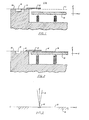
- Figure 3 shows a partial cross sectional view of the workpiece with the focused beam B having a center line CL focused on the center of a fiducial mark M in the top surface 16 of workpiece W.
- Surface 16 is shown accurately located in the calibration plane C. The beam is undeflected in this figure, and impinges perpendicularly on the workpiece.
- the beam remains undeflected, as in Figure 3, but the workpiece W and mark M have been moved a distance X 1 by movement of the XY stage.
- the distance X 1 is stored in the system's control subsystem.
- the distance X 1 is chosen to be equal to, but in any case not greater than, the maximum deflection distance of the beam.
- the beam B is deflected so as to be positioned on the mark M.
- the amount of electronic drive necessary to deflect the beam so as to be positioned on the mark is stored in the system's control subsystem.
- the beam landing angle will have been determined as a function of beam deflection. Also, as part of the system's control subsystem, the landing angle 8 for values of X and Y deflection distances are stored. Thus, with distance X 1 known, the angle 8 is also known.
- Figure 7 shows the stage having been moved a distance X2 with the workpiece thereon.
- X 2 is chosen to be approximately equal to, but in any event not greater than the maximum calibrated beam deflection distance.
- Figure 7 also shows the surface 16 still above the calibration plane by an unknown amount ⁇ Z.
- Figure 8 shows that the beam is again deflected so as to be positioned on the mark M and, if necessary, the afore-mentioned distance X 2 is adjusted by the stage movement to insure that distance X 2 is not greater than the maximum calibrated deflection distance.
- the amount of electronic deflection drive necessary to locate the mark corresponds to a distance X 1 in the calibration plane which is known because of the calibration procedure.
- Angle 6 is also a known value (corresponding to the deflection drive).
- Figure 9 shows the workpiece displaced below the calibration plane and the same procedure is followed as discussed in Figures 1-8 except the sign of the amount of ⁇ Z is reversed. This reversal can be used to determine the direction of displacement of the workpiece surface.
- the magnitude of the landing angle 6 is related to the magnitude of the distance disagreement (X 1 - X 2 ) for a given amount of ⁇ Z. Larger values of the landing angle 6 require more precise determination of ⁇ Z to correct for pattern distortion; but as can be seen from the equation, the determination of ⁇ Z is an error in direct relation to the magnitude of angle 8. Larger values of angle 0 requiring more precise determination of ⁇ Z, produce more accurate values for ⁇ Z. It should be noted also, that precise positioning of the stage is not required as long as the stage can be positioned sufficiently close to the desired location as to make the variation in angle 0 insignificant between locations.
- ⁇ Z and angle 6 are sufficiently small so as to make variations in angle 8 over a beam deflection distance
- ⁇ Z for typical situations is found to be 0.01 millimeters or less and thus
- X 1 - X 21 0.0001 millimeters approximately.
- Figure 10 illustrates another embodiment of the invention where workpiece surface displacement is measured from two fiducial marks located within the beam deflection field.
- the laser interferometer system is not needed.
- the two marks be imprinted on the workpiece surface at a precisely known separation L.
- the beam deflection system is precisely calibrated such that the beam is made to impringe at known distances in the calibration plane, on command. Further, the beam landing angles are known versus beam deflection amounts.
- the stage is moved such that X 1 - X 3 is negligibly small, by making X 1 sufficiently small. Thus, by scanning the fiducial mark M 1 , the distance X 1 is measured.
- the amount of ⁇ Z is then calibrated by placing the undeflected beam near one mark sufficiently close to the center of the field as to make the measured distance X 2 - X 3 negligibly small compared with distances X 2 or X 4 .
- X 2 is approximately equal to L a known value.
- the beam measures X 4 also a known value, hence, ⁇ Z is determined by the formula
Landscapes
- Chemical & Material Sciences (AREA)
- Analytical Chemistry (AREA)
- Electron Beam Exposure (AREA)
- Length-Measuring Devices Using Wave Or Particle Radiation (AREA)
- Exposure And Positioning Against Photoresist Photosensitive Materials (AREA)
Applications Claiming Priority (2)
| Application Number | Priority Date | Filing Date | Title |
|---|---|---|---|
| US73060885A | 1985-05-06 | 1985-05-06 | |
| US730608 | 1985-05-06 |
Publications (1)
| Publication Number | Publication Date |
|---|---|
| EP0201858A2 true EP0201858A2 (de) | 1986-11-20 |
Family
ID=24936020
Family Applications (1)
| Application Number | Title | Priority Date | Filing Date |
|---|---|---|---|
| EP86106224A Withdrawn EP0201858A2 (de) | 1985-05-06 | 1986-05-06 | Höhenfühler eines einem Elektronenstrahl ausgesetzten Substrats |
Country Status (3)
| Country | Link |
|---|---|
| EP (1) | EP0201858A2 (de) |
| JP (1) | JPS6230906A (de) |
| KR (1) | KR860008886A (de) |
Cited By (2)
| Publication number | Priority date | Publication date | Assignee | Title |
|---|---|---|---|---|
| US6407398B1 (en) | 1998-11-17 | 2002-06-18 | Advantest Corporation | Electron beam exposure apparatus and exposure method |
| CN110132204A (zh) * | 2019-06-13 | 2019-08-16 | 湖北航嘉麦格纳座椅系统有限公司 | 一种测量工件的平行面高度差的测量装置 |
-
1986
- 1986-05-06 JP JP61102241A patent/JPS6230906A/ja active Pending
- 1986-05-06 KR KR1019860003501A patent/KR860008886A/ko not_active Ceased
- 1986-05-06 EP EP86106224A patent/EP0201858A2/de not_active Withdrawn
Cited By (2)
| Publication number | Priority date | Publication date | Assignee | Title |
|---|---|---|---|---|
| US6407398B1 (en) | 1998-11-17 | 2002-06-18 | Advantest Corporation | Electron beam exposure apparatus and exposure method |
| CN110132204A (zh) * | 2019-06-13 | 2019-08-16 | 湖北航嘉麦格纳座椅系统有限公司 | 一种测量工件的平行面高度差的测量装置 |
Also Published As
| Publication number | Publication date |
|---|---|
| KR860008886A (ko) | 1986-12-18 |
| JPS6230906A (ja) | 1987-02-09 |
Similar Documents
| Publication | Publication Date | Title |
|---|---|---|
| EP0297247B1 (de) | Verfahren zur Elektronenstrahlaufzeichnung und System in Verbindung mit kontinuierlich verschiebbarem Tisch unter Verwendung von Gross-Bereichsablenkung | |
| CA1150861A (en) | Apparatus for writing patterns in a layer on a substrate by means of a beam of electrically charged particles | |
| US4443703A (en) | Method and apparatus of deflection calibration for a charged particle beam exposure apparatus | |
| US4636968A (en) | Method of positioning a beam to a specific portion of a semiconductor wafer | |
| US6392243B1 (en) | Electron beam exposure apparatus and device manufacturing method | |
| US4792693A (en) | Step-and-repeat exposure method | |
| EP0033138B1 (de) | Verfahren zur Korrektur von Ablenkungsverzerrungen in einem Lithographiegerät mit geladenen Teilchen | |
| EP0431864B1 (de) | Verfahren zur Wahrnehmung und Justierung der Belichtungsbedingungen in einem Belichtungssystem mittels Ladungsträgern und ein solches System | |
| EP0201858A2 (de) | Höhenfühler eines einem Elektronenstrahl ausgesetzten Substrats | |
| US5311026A (en) | Charged particle beam lithography system and method therefor | |
| JP2868548B2 (ja) | アライメント装置 | |
| JP2004311659A (ja) | 荷電粒子線装置の調整方法及び荷電粒子線装置 | |
| JPH08227840A (ja) | 荷電粒子線描画装置における調整方法および描画方法 | |
| US5142154A (en) | Charged-particle beam lithography and cassette for material patterned by charged-particle beam lithographic apparatus | |
| JPH0782987B2 (ja) | 電子線描画装置 | |
| JP2829649B2 (ja) | アライメント装置 | |
| JPH05243136A (ja) | 電子ビーム描画装置を用いたパターン重ね合わせ評価方法 | |
| Russell et al. | Development of SEM-based dedicated IC metrology system | |
| JP3274959B2 (ja) | 半導体露光装置 | |
| JPH09106945A (ja) | 粒子線のアライメント方法及びそれを用いた照射方法並びに装置 | |
| JPS58186009A (ja) | 測長方法 | |
| JP2629768B2 (ja) | 電子ビーム露光装置 | |
| JPH0582731B2 (de) | ||
| JPH0547646A (ja) | 電子線描画方法 | |
| JPH11204408A (ja) | 電子ビーム露光装置における電子ビーム入射角測定方法及びそれを利用した露光方法 |
Legal Events
| Date | Code | Title | Description |
|---|---|---|---|
| PUAI | Public reference made under article 153(3) epc to a published international application that has entered the european phase |
Free format text: ORIGINAL CODE: 0009012 |
|
| AK | Designated contracting states |
Kind code of ref document: A2 Designated state(s): DE GB NL |
|
| STAA | Information on the status of an ep patent application or granted ep patent |
Free format text: STATUS: THE APPLICATION HAS BEEN WITHDRAWN |
|
| 18W | Application withdrawn |
Withdrawal date: 19870302 |
|
| RIN1 | Information on inventor provided before grant (corrected) |
Inventor name: CAVAN, DANIEL L. Inventor name: WIESNER, JOHN C. |