EP0201897B1 - Rundballenpresse - Google Patents
Rundballenpresse Download PDFInfo
- Publication number
- EP0201897B1 EP0201897B1 EP86106415A EP86106415A EP0201897B1 EP 0201897 B1 EP0201897 B1 EP 0201897B1 EP 86106415 A EP86106415 A EP 86106415A EP 86106415 A EP86106415 A EP 86106415A EP 0201897 B1 EP0201897 B1 EP 0201897B1
- Authority
- EP
- European Patent Office
- Prior art keywords
- roll
- scraper
- auger
- crop
- rolls
- Prior art date
- Legal status (The legal status is an assumption and is not a legal conclusion. Google has not performed a legal analysis and makes no representation as to the accuracy of the status listed.)
- Expired
Links
Images
Classifications
-
- A—HUMAN NECESSITIES
- A01—AGRICULTURE; FORESTRY; ANIMAL HUSBANDRY; HUNTING; TRAPPING; FISHING
- A01D—HARVESTING; MOWING
- A01D75/00—Accessories for harvesters or mowers
- A01D75/18—Safety devices for parts of the machines
-
- A—HUMAN NECESSITIES
- A01—AGRICULTURE; FORESTRY; ANIMAL HUSBANDRY; HUNTING; TRAPPING; FISHING
- A01B—SOIL WORKING IN AGRICULTURE OR FORESTRY; PARTS, DETAILS, OR ACCESSORIES OF AGRICULTURAL MACHINES OR IMPLEMENTS, IN GENERAL
- A01B71/00—Construction or arrangement of setting or adjusting mechanisms, of implement or tool drive or of power take-off; Means for protecting parts against dust, or the like; Adapting machine elements to or for agricultural purposes
- A01B71/08—Means for protecting against dust or the like, or for cleaning agricultural implements
-
- A—HUMAN NECESSITIES
- A01—AGRICULTURE; FORESTRY; ANIMAL HUSBANDRY; HUNTING; TRAPPING; FISHING
- A01F—PROCESSING OF HARVESTED PRODUCE; HAY OR STRAW PRESSES; DEVICES FOR STORING AGRICULTURAL OR HORTICULTURAL PRODUCE
- A01F15/00—Baling presses for straw, hay or the like
- A01F15/07—Rotobalers, i.e. machines for forming cylindrical bales by winding and pressing
-
- B—PERFORMING OPERATIONS; TRANSPORTING
- B65—CONVEYING; PACKING; STORING; HANDLING THIN OR FILAMENTARY MATERIAL
- B65G—TRANSPORT OR STORAGE DEVICES, e.g. CONVEYORS FOR LOADING OR TIPPING, SHOP CONVEYOR SYSTEMS OR PNEUMATIC TUBE CONVEYORS
- B65G45/00—Lubricating, cleaning, or clearing devices
- B65G45/10—Cleaning devices
- B65G45/12—Cleaning devices comprising scrapers
-
- A—HUMAN NECESSITIES
- A01—AGRICULTURE; FORESTRY; ANIMAL HUSBANDRY; HUNTING; TRAPPING; FISHING
- A01F—PROCESSING OF HARVESTED PRODUCE; HAY OR STRAW PRESSES; DEVICES FOR STORING AGRICULTURAL OR HORTICULTURAL PRODUCE
- A01F15/00—Baling presses for straw, hay or the like
- A01F15/07—Rotobalers, i.e. machines for forming cylindrical bales by winding and pressing
- A01F2015/078—Pressing chamber formed exclusively by flexible elements, e.g. belts
-
- A—HUMAN NECESSITIES
- A01—AGRICULTURE; FORESTRY; ANIMAL HUSBANDRY; HUNTING; TRAPPING; FISHING
- A01F—PROCESSING OF HARVESTED PRODUCE; HAY OR STRAW PRESSES; DEVICES FOR STORING AGRICULTURAL OR HORTICULTURAL PRODUCE
- A01F15/00—Baling presses for straw, hay or the like
- A01F15/07—Rotobalers, i.e. machines for forming cylindrical bales by winding and pressing
- A01F2015/0795—Pressing chamber with variable volume
-
- A—HUMAN NECESSITIES
- A01—AGRICULTURE; FORESTRY; ANIMAL HUSBANDRY; HUNTING; TRAPPING; FISHING
- A01F—PROCESSING OF HARVESTED PRODUCE; HAY OR STRAW PRESSES; DEVICES FOR STORING AGRICULTURAL OR HORTICULTURAL PRODUCE
- A01F15/00—Baling presses for straw, hay or the like
- A01F15/08—Details
- A01F15/18—Endless belts, rolls or the like
- A01F2015/186—Constructional details of rollers or the bearings of the rollers of the press chamber
Definitions
- This invention relates to a baling machine and a roll assembly for forming cylindrical bales of crop having a frame, rotatable rolls mounted thereon and driven from a drive, and belts trained over the rolls to provide a baling chamber for the crop, a said roll having a scraper assembly which has a scraper for preventing the crop being carried round the roll.
- Machines for forming large cylindrical bales of hay (so called «round» balers) are well known.
- the crop is removed from a windrow by a pick-up mechanism and delivered rearwardly to a baling chamber where it is rolled into a bale between sets of oppositely moving belts, the growing bale rotating about a horizontal axis and the baling chamber expanding with the bale.
- the belts are trained over rolls which extend laterally of the machine and most of which are journalled at either end in the sides of the machine.
- stray crop can become entrapped in the region between the sides of the baler, the outermost belts and the rolls, whereupon the crop tends to wrap round the roll ends which can be detrimental to belt tracking on the rolls.
- the crop can also find its way into the bearings of the rolls and foul them.
- the present invention enables wrapping or build-up of crop on the scraper to be reduced.
- the scraper assembly includes an auger disposed adjacent the scraper so as to move crop away from the scraper, the auger being drivable either directly or indirectly from the drive for the rolls.
- a scraper assembly can be provided at both end regions of the roll in the vicinity of bearings therefor.
- a roll assembly for a baling machine for forming cylindrical bales of crop having a frame, rotatable rolls mounted thereon and connectible to a drive, and belts trained over the rolls, comprises a roll having a said scraper assembly or assemblies.
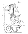
- the machine includes a main frame 10 mounted on a pair of wheels 12, 14.
- the main frame 10 has a pair of upright, opposite, fore-and-aft extending right and left side walls 16, 18 connected by transverse beams.
- a draft tongue 20 is rigid with a cross beam 21 at the front of the frame 10 and extends forwardly for attaching the baler to a tractor (not shown) which draws the machine.
- a plurality of lateral rolls extends over the width of the machine.
- One set of rolls 22, 24, 26, 28, 30, 32 is journalled in a forward fixed portion of either side wall, whilst a further set constituted by rolls 34, 36, 38 is journalled in a rearward swingable gate portion 40 of the side walls.
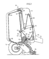
- a belt take-up and tensioning mechanism 64 is provided for this purpose at either side of the machine.
- These mechanisms include: a pair of arms 66, 68 which are mounted on a horizontal transverse pivot shaft 70 at the forward end of the main frame 10; the take-up and tensioning roll 46 which is supported at either end at an intermediate location on the arms 66, 68; and the pair of chamber restricting rolls 42, 44 supported at the free end of the arms.
- the arms are biased in an anti-clockwise direction by a pair of springs one on either side of the main frame 10 of which just the right hand spring 70 is shown and only its arrangement will be described, the other being similar.
- the spring 70 acts through a chain 72, at its lower end, on a bias arm 74 connected rigidly to the pivot shaft 70, the chain 72 being trained over a sprocket 76. At its upper end a further chain similarly connects the spring 70 to one end of a bell crank 78, and the other end of the bell crank bears one end of the take-up and tensioning roll 48.
- the bias arm 74 is also restrained by a piston and cylinder unit 80 pivotally connected at one end to the free end of the bias arm 74 and at the other to the associated right hand side wall 16 of the main frame 10.
- a similar arrangement is provided on the left hand side of the machine so that, for example, the roll - 48 is carried by bell cranks on either side.
- the rear gate portion 40 is movable by a pair of upwardly extending hydraulic piston and cylinder units on either side of the main frame 10 of which only a right hand unit 82 is shown which is pivotally connected at its lower end to the forward fixed portion of the side wall 16 and at its upper end to the gate portion 40 which is swingable upwardly and downwardly about a pivot arrangement 84 at its upper forward region.
- baling chamber 56 In operation, crop lying in a windrow 84 is lifted and conveyed to the baling chamber 56 where - the oppositely moving runs 52, 54 of the belts, - aided by the stripper roll 22, cause the crop to turn clockwise (as viewed in Figures 1 and 2) to form the bale core 62 of increasing size which eventually overcomes the tension in the belts brought about by the tensioning mechanisms, and the arms 66,68 consequently swing upwardly and thus the chamber 56 increases in size to ac- comodate as necessary the bale core 62 as its diameter grows.
- baling crop sometimes finds its way past the edges of the belts of the runs 52, 54 to the exterior of the bale chamber 56. Much stray crop forward of the baling chamber tends to escape due to the staggered array of belts as mentioned above, but some crop can nevertheless sometimes wrap round the roll 26 at its ends where it can be ingested into bearings of the roll or cause problems in belt tracking.
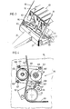
- a scraper assembly 86 is provided at the right hand end of the roll 26, a corresponding assembly 86 being located at the other end.
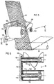
- the right hand assembly 86 illustrated includes (as shown in Figures 3 and 4) a scraper 90, and a mounting plate 92 for the scraper.
- the mounting plate 92 has a semi-circular bite taken from its lower side to accommodate the cylindrical surface of the roll 26 so that the plate straddles the roll, and it is apertured to receive the shanks of two bolts 96 which secure it to the inside face of the right side wall 16.
- the scraper 90 is attached to the plate 92 by way of a V-shaped support 97 welded to, and running at right angles from, the plate so that the scraper 90 extends horizontally over the upper surface of the right hand end portion of the roll 26.
- the scraper 90 is bolted to the support 97 which is provided with adjustment slots (not shown) for the bolts, e.g. for bolt 99.
- the scraper 90 is adjusted on the support 97 to bring the scraper into light contact, or just out of contact, with the roll 26.
- An end belt 101 of the belts 49 is trained over the roll 26, and the scraper 90 extends somewhat beyond the inner edge of this belt.
- Each scraper assembly also includes an auger arrangement 98 of which that in Figures 1 to 3 differs somewhat from that in Figures 4 to 6.
- the arrangement 98 is disposed above the scraper 90 and has an auger 100, a drive roll 102 for the auger 100, a drive chain 104 between the drive roll and the auger, and a support plate 106 for the drive roll and auger.
- the support plate 106 is attached to the right side wall 16 by bolts 107 running through adjustment slots 108 in the plate and carries rigid with it in cantilever fashion a drive roll support cylinder 110 and an auger support cylinder 112 which extend inwardly.
- Jour- nailed within cylinders 110 and 112 are a drive roll shaft 114 and an auger shaft 116 respectively which are rigid with the drive roll 102 and the auger 100.
- the inner ends of the two shafts 114, 116 carry sprockets 118 for the drive chain 104 which connects them.
- the drive chain 104 and sprockets 118 are accommodated in a recess 120 formed on the outer side of the support plate 106.
- the support plate 106 is adjusted to bring the roll 102 into firm frictional driving contact with the forward side-of the belt 101, and in order to ensure a high grip the roll 102 is provided with a rubber surface layer 122.
- the auger 100 is disposed on the rearward side of the belt 101. Viewing the scraper 90 in cross-section as in Figure 4, initially the scraper extends outwardly from the roll 26 at an angle of approximately 45° to the vertical and finally its outer end portion is vertical terminating just short of the underside of the auger 100 roughly in the vertical plane of the axis of the auger.
- the auger arrangement 98 in Figures 1 to 3 differs from that in Figures 4 to 6 in that the auger 100 is arranged to be driven not from one of the belts 49 but from a chain drive 124 for the rolls, only the left hand chain drive being shown in Figure 3.
- a sprocket 126 on a shaft 128 engages the chain drive 124 and the drive is transmitted to the auger 100 which is on the shaft 128.
- the scraper assemblies 86 at the left and rigth hand ends of the roll 26 correspond.
- the scraper assemblies 86 operate by conveying any stray crop tending to wrap round the end portion of the roll 26 away from the end.
- the augers 100 are so disposed relative to the scrapers 90 and are of such a hand that they move any crop, tending to accumulate in the region of the scrapers, away from the scrapers in an inward direction. At the exit ends of the augers the crop is free to fall through the gap between neighbouring belts.
- a single auger driven at one end only, may be used, the auger flights being of opposite hand at the end portions of the auger.
- the scraper can also extend over the full length of the roll.
- scraper assemblies have been described as being located at the end regions of the roll 26, they can alternatively or in addition be provided for other rolls wherever wrapping is likely and where the unwanted stray crop can be moved away from the site of wrapping.
Landscapes
- Life Sciences & Earth Sciences (AREA)
- Environmental Sciences (AREA)
- Engineering & Computer Science (AREA)
- Mechanical Engineering (AREA)
- Soil Sciences (AREA)
- Soil Working Implements (AREA)
- Harvesting Machines For Root Crops (AREA)
- Harvester Elements (AREA)
- Storage Of Harvested Produce (AREA)
- Harvesting Machines For Specific Crops (AREA)
- Agricultural Machines (AREA)
- Outside Dividers And Delivering Mechanisms For Harvesters (AREA)
Claims (17)
Applications Claiming Priority (2)
| Application Number | Priority Date | Filing Date | Title |
|---|---|---|---|
| GB08512087A GB2174954B (en) | 1985-05-13 | 1985-05-13 | Baling machine |
| GB8512087 | 1985-05-13 |
Publications (2)
| Publication Number | Publication Date |
|---|---|
| EP0201897A1 EP0201897A1 (de) | 1986-11-20 |
| EP0201897B1 true EP0201897B1 (de) | 1989-09-06 |
Family
ID=10579063
Family Applications (3)
| Application Number | Title | Priority Date | Filing Date |
|---|---|---|---|
| EP86106415A Expired EP0201897B1 (de) | 1985-05-13 | 1986-05-12 | Rundballenpresse |
| EP86106416A Expired EP0201898B1 (de) | 1985-05-13 | 1986-05-12 | Rundballenpresse |
| EP86106417A Expired EP0201899B1 (de) | 1985-05-13 | 1986-05-12 | Rundballenpresse |
Family Applications After (2)
| Application Number | Title | Priority Date | Filing Date |
|---|---|---|---|
| EP86106416A Expired EP0201898B1 (de) | 1985-05-13 | 1986-05-12 | Rundballenpresse |
| EP86106417A Expired EP0201899B1 (de) | 1985-05-13 | 1986-05-12 | Rundballenpresse |
Country Status (6)
| Country | Link |
|---|---|
| US (1) | US4648239A (de) |
| EP (3) | EP0201897B1 (de) |
| CA (1) | CA1258000A (de) |
| DE (3) | DE3665391D1 (de) |
| ES (6) | ES8707406A1 (de) |
| GB (1) | GB2174954B (de) |
Cited By (1)
| Publication number | Priority date | Publication date | Assignee | Title |
|---|---|---|---|---|
| DE4112774A1 (de) * | 1991-04-19 | 1992-10-22 | Deere & Co | Zugmittelfoerderer |
Families Citing this family (20)
| Publication number | Priority date | Publication date | Assignee | Title |
|---|---|---|---|---|
| DE3610970A1 (de) * | 1986-04-02 | 1987-10-08 | Zweegers & Zonen P J | Rundballenpresse fuer landwirtschaftliches halmgut |
| US4910949A (en) * | 1989-01-17 | 1990-03-27 | Vermeer Manufacturing Co. | Crop material guide means in a machine for forming cylindrical bales |
| GB2233930A (en) * | 1989-06-28 | 1991-01-23 | Deere & Co | Shield device for baling machine |
| US5138942A (en) * | 1991-01-28 | 1992-08-18 | Gehl Company | Belt type round baler with adjustable bale starting chamber |
| DE4113311A1 (de) * | 1991-04-24 | 1992-10-29 | Deere & Co | Vorrichtung zum verhindern eines materialaufbaus |
| US5191833A (en) * | 1992-04-16 | 1993-03-09 | Ford New Holland, Inc. | Roll stripping apparatus for round baler |
| US5417043A (en) * | 1994-09-08 | 1995-05-23 | Vermeer Manufacturing Company | Notched belts for a baler of large cylindrical bales |
| NL1000487C2 (nl) * | 1995-06-02 | 1996-12-03 | Greenland Geldrop Bv | Oogstmachine. |
| US5941168A (en) * | 1998-04-14 | 1999-08-24 | Agco Corporation | Silage round baler |
| US6655121B1 (en) | 2000-08-10 | 2003-12-02 | Gehl Company | Powered feed roller system for a round baler |
| US6477824B2 (en) * | 2001-01-24 | 2002-11-12 | Agco Corporation | Round baler having incoming crop deflectors |
| US6763761B1 (en) | 2003-02-28 | 2004-07-20 | New Holland North America, Inc. | Wiper for twine knife striker plate |
| DE10335883A1 (de) * | 2003-08-06 | 2005-08-18 | Deere & Company, Moline | Rundballenpresse |
| EP1520466B1 (de) * | 2003-09-30 | 2017-05-03 | Deere & Company | Rundballenpresse |
| US7124568B2 (en) * | 2004-05-27 | 2006-10-24 | Cnh America Llc | Adjustable rotor stripper mount for a round baler |
| US8037814B1 (en) * | 2010-04-27 | 2011-10-18 | Cnh America Llc | Method of staggering belts in a round baler |
| TWI535461B (zh) * | 2011-03-11 | 2016-06-01 | 諾金私人有限公司 | 結腸清潔溶液、用於製備該溶液之組成物、包含該組成物或溶液之套組、與製備該溶液之方法 |
| BE1023925B1 (nl) | 2016-03-01 | 2017-09-13 | Cnh Industrial Belgium Nv | Toevoertoestel voor maaidorser |
| DE102018207878A1 (de) * | 2018-05-18 | 2019-11-21 | Deere & Company | Pressmittelleiteinrichtung und Presse |
| CN117502000B (zh) * | 2023-11-09 | 2026-01-06 | 新疆钵施然智能农机股份有限公司 | 一种打捆机构的滚圆装置及打捆机构 |
Family Cites Families (10)
| Publication number | Priority date | Publication date | Assignee | Title |
|---|---|---|---|---|
| DE7430874U (de) * | 1974-09-13 | 1977-05-26 | Welger Geb | Aufsammel-rollballenpresse |
| FR2300023A1 (fr) * | 1975-02-05 | 1976-09-03 | Joy Sa | Dispositif de decrassage de bandes transporteuses |
| US4172354A (en) * | 1977-01-28 | 1979-10-30 | Vermeer Manufacturing Company | Machine for forming large round bales of crop material |
| US4182101A (en) * | 1977-12-01 | 1980-01-08 | Hesston Corporation | Machine for coiling fibrous crop materials into large round bales |
| GB2023525B (en) * | 1978-02-09 | 1982-08-11 | Pritchard A | Cleaning conveyors |
| US4228638A (en) * | 1978-10-26 | 1980-10-21 | Deere & Company | Preservative applicator for a round baler |
| US4422374A (en) * | 1981-12-21 | 1983-12-27 | Sperry Corporation | Baling machine with air spring means for maintaining apron tension |
| US4436027A (en) * | 1982-04-28 | 1984-03-13 | Sperry Corporation | Stripper bar for roll baling machine |
| DE3463888D1 (en) * | 1984-02-15 | 1987-07-02 | Deere & Co | Baling machine |
| US4510741A (en) * | 1984-03-19 | 1985-04-16 | Gehl Company | Rotary crop baler |
-
1985
- 1985-05-13 GB GB08512087A patent/GB2174954B/en not_active Expired
-
1986
- 1986-05-01 US US06/858,467 patent/US4648239A/en not_active Expired - Fee Related
- 1986-05-05 CA CA000508424A patent/CA1258000A/en not_active Expired
- 1986-05-12 EP EP86106415A patent/EP0201897B1/de not_active Expired
- 1986-05-12 ES ES554876A patent/ES8707406A1/es not_active Expired
- 1986-05-12 EP EP86106416A patent/EP0201898B1/de not_active Expired
- 1986-05-12 ES ES554878A patent/ES8800575A1/es not_active Expired
- 1986-05-12 DE DE8686106416T patent/DE3665391D1/de not_active Expired
- 1986-05-12 ES ES554877A patent/ES8707075A1/es not_active Expired
- 1986-05-12 DE DE8686106415T patent/DE3665389D1/de not_active Expired
- 1986-05-12 EP EP86106417A patent/EP0201899B1/de not_active Expired
- 1986-05-12 DE DE8686106417T patent/DE3665392D1/de not_active Expired
- 1986-11-24 ES ES557222A patent/ES8706364A1/es not_active Expired
- 1986-11-24 ES ES557221A patent/ES8706363A1/es not_active Expired
- 1986-12-05 ES ES557249A patent/ES8706365A1/es not_active Expired
Cited By (1)
| Publication number | Priority date | Publication date | Assignee | Title |
|---|---|---|---|---|
| DE4112774A1 (de) * | 1991-04-19 | 1992-10-22 | Deere & Co | Zugmittelfoerderer |
Also Published As
| Publication number | Publication date |
|---|---|
| ES8707075A1 (es) | 1987-07-16 |
| ES557221A0 (es) | 1987-07-01 |
| GB2174954A (en) | 1986-11-19 |
| ES8706363A1 (es) | 1987-07-01 |
| ES8800575A1 (es) | 1987-11-16 |
| ES557222A0 (es) | 1987-07-01 |
| DE3665391D1 (en) | 1989-10-12 |
| US4648239A (en) | 1987-03-10 |
| ES554876A0 (es) | 1987-08-01 |
| EP0201898B1 (de) | 1989-09-06 |
| EP0201897A1 (de) | 1986-11-20 |
| DE3665389D1 (en) | 1989-10-12 |
| EP0201898A1 (de) | 1986-11-20 |
| ES554878A0 (es) | 1987-11-16 |
| ES8706365A1 (es) | 1987-07-01 |
| GB2174954B (en) | 1988-11-30 |
| ES557249A0 (es) | 1987-07-01 |
| ES8706364A1 (es) | 1987-07-01 |
| CA1258000A (en) | 1989-08-01 |
| EP0201899A1 (de) | 1986-11-20 |
| GB8512087D0 (en) | 1985-06-19 |
| ES8707406A1 (es) | 1987-08-01 |
| ES554877A0 (es) | 1987-07-16 |
| EP0201899B1 (de) | 1989-09-06 |
| DE3665392D1 (en) | 1989-10-12 |
Similar Documents
| Publication | Publication Date | Title |
|---|---|---|
| EP0201899B1 (de) | Rundballenpresse | |
| EP0151665B1 (de) | Rundballenpresse | |
| CA2260409C (en) | Windrower specialty crop platform having right-and left-hand cantilevered augers located beneath a full-length center-feed auger | |
| GB2217253A (en) | Baling machine for forming cylindrical bales of crop | |
| US4633659A (en) | Cylindrical bale-forming press | |
| EP0286776A1 (de) | Aufnahme-Trommel und Rundballenpresse | |
| US5080009A (en) | Round baler having trash discharge mechanism | |
| GB2092086A (en) | Screw conveyor | |
| US4993217A (en) | Machine for forming cylindrical bales of crop | |
| US4425753A (en) | Clutch mechanism for baling machine | |
| EP0330975A1 (de) | Vorrichtung um Rundballen bei der Ernte zu rollen | |
| US4424662A (en) | Drive apparatus for roll baling machine | |
| EP0287704B1 (de) | Rundballenpresse | |
| EP0405129B1 (de) | Maschine zum Formen zylindrischer Ballen aus Futterpflanzen | |
| EP0381085B1 (de) | Rundballenpresse | |
| US5408925A (en) | Trash removal apparatus for a round baler | |
| EP0383076A1 (de) | Rundballenpresse | |
| GB2105644A (en) | Baling machines | |
| US20240423138A1 (en) | Consistent flow windguard for agricultural baler | |
| US5327711A (en) | Baler feeding apparatus | |
| US5417043A (en) | Notched belts for a baler of large cylindrical bales | |
| CA1206795A (en) | Drive apparatus for roll baling machine |
Legal Events
| Date | Code | Title | Description |
|---|---|---|---|
| PUAI | Public reference made under article 153(3) epc to a published international application that has entered the european phase |
Free format text: ORIGINAL CODE: 0009012 |
|
| AK | Designated contracting states |
Kind code of ref document: A1 Designated state(s): DE FR GB IT NL |
|
| 17P | Request for examination filed |
Effective date: 19861122 |
|
| 17Q | First examination report despatched |
Effective date: 19880321 |
|
| ITF | It: translation for a ep patent filed | ||
| GRAA | (expected) grant |
Free format text: ORIGINAL CODE: 0009210 |
|
| AK | Designated contracting states |
Kind code of ref document: B1 Designated state(s): DE FR GB IT NL |
|
| REF | Corresponds to: |
Ref document number: 3665389 Country of ref document: DE Date of ref document: 19891012 |
|
| ET | Fr: translation filed | ||
| PLBE | No opposition filed within time limit |
Free format text: ORIGINAL CODE: 0009261 |
|
| STAA | Information on the status of an ep patent application or granted ep patent |
Free format text: STATUS: NO OPPOSITION FILED WITHIN TIME LIMIT |
|
| 26N | No opposition filed | ||
| ITTA | It: last paid annual fee | ||
| PGFP | Annual fee paid to national office [announced via postgrant information from national office to epo] |
Ref country code: GB Payment date: 19930419 Year of fee payment: 8 |
|
| PGFP | Annual fee paid to national office [announced via postgrant information from national office to epo] |
Ref country code: FR Payment date: 19930513 Year of fee payment: 8 |
|
| PGFP | Annual fee paid to national office [announced via postgrant information from national office to epo] |
Ref country code: NL Payment date: 19930531 Year of fee payment: 8 |
|
| PGFP | Annual fee paid to national office [announced via postgrant information from national office to epo] |
Ref country code: DE Payment date: 19930703 Year of fee payment: 8 |
|
| PG25 | Lapsed in a contracting state [announced via postgrant information from national office to epo] |
Ref country code: GB Effective date: 19940512 |
|
| PG25 | Lapsed in a contracting state [announced via postgrant information from national office to epo] |
Ref country code: NL Effective date: 19941201 |
|
| GBPC | Gb: european patent ceased through non-payment of renewal fee |
Effective date: 19940512 |
|
| NLV4 | Nl: lapsed or anulled due to non-payment of the annual fee | ||
| PG25 | Lapsed in a contracting state [announced via postgrant information from national office to epo] |
Ref country code: FR Effective date: 19950131 |
|
| PG25 | Lapsed in a contracting state [announced via postgrant information from national office to epo] |
Ref country code: DE Effective date: 19950201 |
|
| REG | Reference to a national code |
Ref country code: FR Ref legal event code: ST |
|
| PGFP | Annual fee paid to national office [announced via postgrant information from national office to epo] |
Ref country code: IT Payment date: 20050528 Year of fee payment: 20 |