EP0201911A1 - Vorrichtung zur Orientierung der Führungsköpfe einer Drahtelektrode für Elektroerosionsschneiden - Google Patents
Vorrichtung zur Orientierung der Führungsköpfe einer Drahtelektrode für Elektroerosionsschneiden Download PDFInfo
- Publication number
- EP0201911A1 EP0201911A1 EP86106466A EP86106466A EP0201911A1 EP 0201911 A1 EP0201911 A1 EP 0201911A1 EP 86106466 A EP86106466 A EP 86106466A EP 86106466 A EP86106466 A EP 86106466A EP 0201911 A1 EP0201911 A1 EP 0201911A1
- Authority
- EP
- European Patent Office
- Prior art keywords
- heads
- wire
- cylinders
- guide
- orienting
- Prior art date
- Legal status (The legal status is an assumption and is not a legal conclusion. Google has not performed a legal analysis and makes no representation as to the accuracy of the status listed.)
- Granted
Links
- 238000006073 displacement reaction Methods 0.000 claims abstract description 3
- 238000000034 method Methods 0.000 claims description 3
- 238000013519 translation Methods 0.000 claims 1
- 230000014616 translation Effects 0.000 claims 1
- 238000009434 installation Methods 0.000 description 4
- 238000002347 injection Methods 0.000 description 2
- 239000007924 injection Substances 0.000 description 2
- 238000003754 machining Methods 0.000 description 2
- 238000005452 bending Methods 0.000 description 1
- 230000007547 defect Effects 0.000 description 1
- 239000012530 fluid Substances 0.000 description 1
- 239000007788 liquid Substances 0.000 description 1
- 239000000243 solution Substances 0.000 description 1
Images

Classifications
-
- B—PERFORMING OPERATIONS; TRANSPORTING
- B23—MACHINE TOOLS; METAL-WORKING NOT OTHERWISE PROVIDED FOR
- B23H—WORKING OF METAL BY THE ACTION OF A HIGH CONCENTRATION OF ELECTRIC CURRENT ON A WORKPIECE USING AN ELECTRODE WHICH TAKES THE PLACE OF A TOOL; SUCH WORKING COMBINED WITH OTHER FORMS OF WORKING OF METAL
- B23H7/00—Processes or apparatus applicable to both electrical discharge machining and electrochemical machining
- B23H7/02—Wire-cutting
- B23H7/06—Control of the travel curve of the relative movement between electrode and workpiece
Definitions
- the object of the invention is to provide an installation fulfilling the same functions as those of known systems but with simpler and less bulky means.
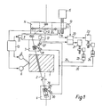
- FIG. 1 which very schematically shows different parts of an electroerosion cutting installation using the invention
- 1 designates the part to be cut
- 2 the wire electrode
- 3 the upper guide head
- 4 the lower guide head
- 5 and 6 two motors used to move the part 1 in the direction x, respectively y.
- the upper guide head 3 is carried by a cross table, the plates 7 and 8 of which are driven by the motors 11 and 12 in two different directions u and v, parallel to the cutting plane.
- These motors, as well as motors 5 and 6, are controlled by a digital control unit 13.
- the cross table is itself supported by a base 14 which can be moved vertically under the action of a motor 15 to adapt the spacing between the guide heads to of reference for identical parts.
- the numbers 31 and 32 designate the upper part and the lower part of a housing in which the guide head proper 33 is mounted, which comprises a tube 34 doubled at one end of a sheath 35 and comprising near its other end a guide 36 whose orifice is used for centering the wire electrode (not shown in Figures 2-4) passing through the tube.
- This is held in a lower ball 37 centered on the guide hole and slides in an upper ball 38 which surrounds the tube approximately in the middle.
- the lower ball 37 is mounted in a lower cage 41 secured to the lower part 32 of the housing.
- the upper ball joint 38 is mounted in an upper cage 42 driven by an upper plate 44 which can slide in direction v (FIG. 2) under the action of a receiving cylinder 46 and driven by a lower plate 43 which can slide in direction u under the action of a receiving cylinder 45.
- Each plate 43 and 44 has a slot 49, 50 respectively perpendicular to the direction of its movement so as to ensure the independence of the movements of these plates.
- the pistons of the receiving cylinders 45 and 46 are recalled that this arrangement makes it possible to orient the guide head 33 with precision by the action of a pressurized fluid acting on the receiving cylinders 45 and 46.
- Figure 3 shows this guide head in an upright position and Figure 4 shows the same guide head in an inclined position.
Landscapes
- Chemical & Material Sciences (AREA)
- Chemical Kinetics & Catalysis (AREA)
- Electrochemistry (AREA)
- Engineering & Computer Science (AREA)
- Mechanical Engineering (AREA)
- Electrical Discharge Machining, Electrochemical Machining, And Combined Machining (AREA)
Applications Claiming Priority (2)
| Application Number | Priority Date | Filing Date | Title |
|---|---|---|---|
| CH2122/85A CH666431A5 (fr) | 1985-05-17 | 1985-05-17 | Dispositif pour orienter les tetes de guidage d'un fil-electrode pour decoupage par electroerosion. |
| CH2122/85 | 1985-05-17 |
Publications (2)
| Publication Number | Publication Date |
|---|---|
| EP0201911A1 true EP0201911A1 (de) | 1986-11-20 |
| EP0201911B1 EP0201911B1 (de) | 1989-04-19 |
Family
ID=4226393
Family Applications (1)
| Application Number | Title | Priority Date | Filing Date |
|---|---|---|---|
| EP86106466A Expired EP0201911B1 (de) | 1985-05-17 | 1986-05-13 | Vorrichtung zur Orientierung der Führungsköpfe einer Drahtelektrode für Elektroerosionsschneiden |
Country Status (5)
| Country | Link |
|---|---|
| US (1) | US4751362A (de) |
| EP (1) | EP0201911B1 (de) |
| JP (1) | JPS61265215A (de) |
| CH (1) | CH666431A5 (de) |
| DE (2) | DE3662848D1 (de) |
Families Citing this family (12)
| Publication number | Priority date | Publication date | Assignee | Title |
|---|---|---|---|---|
| CH670590A5 (de) * | 1987-04-03 | 1989-06-30 | Charmilles Technologies | |
| JPH0692047B2 (ja) * | 1988-10-05 | 1994-11-16 | ブラザー工業株式会社 | ワイヤ放電加工機のテーパ加工装置 |
| US5214260A (en) * | 1991-04-03 | 1993-05-25 | Fort Wayne Wire Die, Inc. | Electrical discharge machine wire electrode guiding device |
| DE4222186C2 (de) * | 1992-07-06 | 1996-06-20 | Agie Ag Ind Elektronik | Verfahren zum funkenerosiven Feinbearbeiten mittels drahtförmiger Elektroden und funkenerosive Schneidevorrichtung |
| US5519181A (en) * | 1994-07-06 | 1996-05-21 | Hsu; Wan-I | Apparatus for guiding a wire electrode on a machine tool |
| DE19506775C2 (de) * | 1995-02-27 | 1997-09-25 | Agie Ag Ind Elektronik | Vorrichtung zum Führen einer Bearbeitungselektrode an einer Funkenerosionsmaschine |
| DE19715687A1 (de) * | 1997-04-15 | 1998-10-22 | Agie Ag Ind Elektronik | Funkenerosionsmaschine mit wenigstens einer Drahtelektrode und Verfahren zur Bearbeitung eines Werkstückes in einer Funkenerosionsmaschine |
| JP3453380B2 (ja) * | 2002-01-23 | 2003-10-06 | 後藤電子 株式会社 | 線条体の水中搬送装置および線条体の水中搬送方法 |
| US7273994B2 (en) * | 2004-11-03 | 2007-09-25 | Castek Mechatron Industry Co., Ltd. | Electrical discharge machine for improving the guide alignment base structure |
| JP5220111B2 (ja) | 2008-07-29 | 2013-06-26 | 三菱電機株式会社 | 細孔放電加工装置及び放電加工方法 |
| US9452482B2 (en) * | 2011-04-19 | 2016-09-27 | Kurashiki System Design Co., Ltd. | Electrical discharge machine |
| JP2015136767A (ja) * | 2014-01-23 | 2015-07-30 | ファナック株式会社 | ワイヤ放電加工機の加工液噴出装置 |
Citations (2)
| Publication number | Priority date | Publication date | Assignee | Title |
|---|---|---|---|---|
| EP0084083A2 (de) * | 1982-01-04 | 1983-07-27 | Erowa AG | Drahtführungseinrichtung für elektroerosive Bearbeitungsmaschinen |
| US4431896A (en) * | 1979-04-26 | 1984-02-14 | A.G. Fur Industrielle Elektronik Agie | Method and apparatus for orienting the wire guidance heads on spark erosion cutting equipment for eroding with a great wire slope |
Family Cites Families (6)
| Publication number | Priority date | Publication date | Assignee | Title |
|---|---|---|---|---|
| US3731045A (en) * | 1971-07-01 | 1973-05-01 | Agie Ag Ind Elektronik | Circuit for an electro-eroding machine for the control of the relative movement between at least one electrode and at least one workpiece |
| US3946189A (en) * | 1971-11-09 | 1976-03-23 | Ing. C. Olivetti & C., S.P.A. | Electroerosion apparatus having a cyclically movable and variably inclined wire electrode |
| US4114015A (en) * | 1974-05-27 | 1978-09-12 | Vladimir Sergeevich Vasiliev | Electric discharge machine with a program copier and a tool support head carried by a longitudinally and transversely driven carriage |
| US4386248A (en) * | 1978-10-06 | 1983-05-31 | Inoue-Japax Research Incorporated | Electrical machining method and apparatus for forming a 3D surface contour in a workpiece with a traveling-wire electrode |
| JPS5639832A (en) * | 1979-09-06 | 1981-04-15 | Fanuc Ltd | Wire cut electric discharge machining method |
| DE3511929A1 (de) * | 1985-04-01 | 1986-10-02 | Aktiengesellschaft für Industrielle Elektronik Agie, Losone/Locarno | Elektroerosionsmaschine |
-
1985
- 1985-05-17 CH CH2122/85A patent/CH666431A5/fr not_active IP Right Cessation
-
1986
- 1986-05-12 JP JP61108387A patent/JPS61265215A/ja active Pending
- 1986-05-13 EP EP86106466A patent/EP0201911B1/de not_active Expired
- 1986-05-13 DE DE8686106466T patent/DE3662848D1/de not_active Expired
- 1986-05-15 DE DE8613193U patent/DE8613193U1/de not_active Expired
- 1986-05-16 US US06/863,958 patent/US4751362A/en not_active Expired - Lifetime
Patent Citations (2)
| Publication number | Priority date | Publication date | Assignee | Title |
|---|---|---|---|---|
| US4431896A (en) * | 1979-04-26 | 1984-02-14 | A.G. Fur Industrielle Elektronik Agie | Method and apparatus for orienting the wire guidance heads on spark erosion cutting equipment for eroding with a great wire slope |
| EP0084083A2 (de) * | 1982-01-04 | 1983-07-27 | Erowa AG | Drahtführungseinrichtung für elektroerosive Bearbeitungsmaschinen |
Also Published As
| Publication number | Publication date |
|---|---|
| US4751362A (en) | 1988-06-14 |
| DE8613193U1 (de) | 1986-11-20 |
| JPS61265215A (ja) | 1986-11-25 |
| CH666431A5 (fr) | 1988-07-29 |
| EP0201911B1 (de) | 1989-04-19 |
| DE3662848D1 (en) | 1989-05-24 |
Similar Documents
| Publication | Publication Date | Title |
|---|---|---|
| EP0201911A1 (de) | Vorrichtung zur Orientierung der Führungsköpfe einer Drahtelektrode für Elektroerosionsschneiden | |
| FR2537029A1 (fr) | Appareil a laser pour traiter des materiaux | |
| EP0210080B1 (de) | Verfahren und Einrichtung zur Bearbeitung eines hohlen Werkstückes durch Fräsung entlang einer vorbestimmten Linie | |
| EP0371896A1 (de) | Mikroschlaggerät für Markierung | |
| CA2058881A1 (fr) | Microsoudeuse pour fibres optiques et procede de soudage a l'aide de cette microsoudeuse | |
| EP0036376A1 (de) | Automatisch verstellbare Vorschub- und Spannvorrichtung für die genaue Position einer Stange, z.B. anwendbar bei Abschneidmaschinen | |
| WO1999061198A2 (fr) | Structure kinematique parallele d'une machine-outil | |
| EP0819504B1 (de) | Stanzvorrichtung zum Bohren von Leiterplatten | |
| EP0399925B1 (de) | Vorrichtung zum Bearbeiten des Kurbelwellenlagers einer thermischen Maschine | |
| EP0348534B1 (de) | Drahtschneidemaschine für Elektroerosionsbearbeitung | |
| FR2548941A1 (fr) | Robot a bras coude pour le decoupage | |
| EP0003930A1 (de) | Vorrichtung zum gleichzeitigen Einlegen mehrerer optischer Fasern in mehrere schraubenförmig auf einem zylindrischen Träger verlaufenden Nuten | |
| CH659605A5 (fr) | Machine d'electroerosion pour l'etincelage par fil et pour l'enfoncage. | |
| US4453070A (en) | Apparatus for orienting the wire electrode support and guide member and the machining fluid nozzle of a travelling wire EDM apparatus | |
| CH652334A5 (fr) | Machine a rectifier. | |
| FR2611155A1 (fr) | Dispositif de soudage aux ultrasons notamment pour des composants semi-conducteurs avec un guidage axial et radial de la tete de soudage rotative | |
| FR2612826A1 (fr) | Machine-outil pour le travail de pieces de bois | |
| AU613054B2 (en) | Perfected robot | |
| EP0064068B1 (de) | Einrichtung zum orientieren eines führungskopfes einer funkenerosionsschneidemaschine | |
| FR2544239A1 (fr) | Dispositif destine au fraisage de rainures | |
| FR2535637A1 (fr) | Procede et dispositif d'usinage par decharges electriques avec un support de soutien du fil mobile | |
| EP0554629B1 (de) | Honmaschine mit ausdehnbarem Werkzeug | |
| EP0171763B1 (de) | Selbsttätige Zentriervorrichtung zur Führung eines Messinstrumentes oder eines Werkzeuges bezüglich eines länglichen Werkstückes | |
| EP0007462B1 (de) | Vorrichtung zum Kopieren nach einer Schablone | |
| SU1170638A1 (ru) | Устройство дл изготовлени печатных схем из фольгированных материалов |
Legal Events
| Date | Code | Title | Description |
|---|---|---|---|
| PUAI | Public reference made under article 153(3) epc to a published international application that has entered the european phase |
Free format text: ORIGINAL CODE: 0009012 |
|
| AK | Designated contracting states |
Kind code of ref document: A1 Designated state(s): DE FR GB IT |
|
| 17P | Request for examination filed |
Effective date: 19870514 |
|
| 17Q | First examination report despatched |
Effective date: 19870911 |
|
| RAP1 | Party data changed (applicant data changed or rights of an application transferred) |
Owner name: CHARMILLES TECHNOLOGIES S.A. |
|
| ITF | It: translation for a ep patent filed | ||
| GRAA | (expected) grant |
Free format text: ORIGINAL CODE: 0009210 |
|
| AK | Designated contracting states |
Kind code of ref document: B1 Designated state(s): DE FR GB IT |
|
| GBT | Gb: translation of ep patent filed (gb section 77(6)(a)/1977) | ||
| REF | Corresponds to: |
Ref document number: 3662848 Country of ref document: DE Date of ref document: 19890524 |
|
| PLBE | No opposition filed within time limit |
Free format text: ORIGINAL CODE: 0009261 |
|
| STAA | Information on the status of an ep patent application or granted ep patent |
Free format text: STATUS: NO OPPOSITION FILED WITHIN TIME LIMIT |
|
| 26N | No opposition filed | ||
| ITTA | It: last paid annual fee | ||
| REG | Reference to a national code |
Ref country code: GB Ref legal event code: IF02 |
|
| PGFP | Annual fee paid to national office [announced via postgrant information from national office to epo] |
Ref country code: GB Payment date: 20030428 Year of fee payment: 18 |
|
| PGFP | Annual fee paid to national office [announced via postgrant information from national office to epo] |
Ref country code: FR Payment date: 20030512 Year of fee payment: 18 |
|
| PGFP | Annual fee paid to national office [announced via postgrant information from national office to epo] |
Ref country code: DE Payment date: 20030514 Year of fee payment: 18 |
|
| PG25 | Lapsed in a contracting state [announced via postgrant information from national office to epo] |
Ref country code: GB Free format text: LAPSE BECAUSE OF NON-PAYMENT OF DUE FEES Effective date: 20040513 |
|
| PG25 | Lapsed in a contracting state [announced via postgrant information from national office to epo] |
Ref country code: DE Free format text: LAPSE BECAUSE OF NON-PAYMENT OF DUE FEES Effective date: 20041201 |
|
| GBPC | Gb: european patent ceased through non-payment of renewal fee |
Effective date: 20040513 |
|
| PG25 | Lapsed in a contracting state [announced via postgrant information from national office to epo] |
Ref country code: FR Free format text: LAPSE BECAUSE OF NON-PAYMENT OF DUE FEES Effective date: 20050131 |
|
| REG | Reference to a national code |
Ref country code: FR Ref legal event code: ST |
|
| PG25 | Lapsed in a contracting state [announced via postgrant information from national office to epo] |
Ref country code: IT Free format text: LAPSE BECAUSE OF NON-PAYMENT OF DUE FEES;WARNING: LAPSES OF ITALIAN PATENTS WITH EFFECTIVE DATE BEFORE 2007 MAY HAVE OCCURRED AT ANY TIME BEFORE 2007. THE CORRECT EFFECTIVE DATE MAY BE DIFFERENT FROM THE ONE RECORDED. Effective date: 20050513 |