EP0201923B1 - Verfahren zum Beschichten fester Körper mit Schmiermitteln - Google Patents
Verfahren zum Beschichten fester Körper mit Schmiermitteln Download PDFInfo
- Publication number
- EP0201923B1 EP0201923B1 EP19860106571 EP86106571A EP0201923B1 EP 0201923 B1 EP0201923 B1 EP 0201923B1 EP 19860106571 EP19860106571 EP 19860106571 EP 86106571 A EP86106571 A EP 86106571A EP 0201923 B1 EP0201923 B1 EP 0201923B1
- Authority
- EP
- European Patent Office
- Prior art keywords
- lubricant
- lubricants
- solid
- process according
- coating
- Prior art date
- Legal status (The legal status is an assumption and is not a legal conclusion. Google has not performed a legal analysis and makes no representation as to the accuracy of the status listed.)
- Expired - Lifetime
Links
- 239000000314 lubricant Substances 0.000 title claims abstract description 54
- 238000000034 method Methods 0.000 title claims abstract description 27
- 239000007787 solid Substances 0.000 title claims abstract description 18
- 238000000576 coating method Methods 0.000 title claims abstract description 16
- 239000011248 coating agent Substances 0.000 title claims abstract description 13
- 230000005686 electrostatic field Effects 0.000 claims description 13
- 229910052751 metal Inorganic materials 0.000 claims description 13
- 239000002184 metal Substances 0.000 claims description 13
- 239000007788 liquid Substances 0.000 claims description 9
- 239000007921 spray Substances 0.000 claims description 3
- 150000002739 metals Chemical class 0.000 claims description 2
- 238000000465 moulding Methods 0.000 claims 1
- 239000010410 layer Substances 0.000 description 7
- 238000005461 lubrication Methods 0.000 description 6
- 239000003973 paint Substances 0.000 description 5
- 239000004033 plastic Substances 0.000 description 5
- 229920003023 plastic Polymers 0.000 description 5
- 239000003795 chemical substances by application Substances 0.000 description 4
- 239000000843 powder Substances 0.000 description 4
- 239000001993 wax Substances 0.000 description 3
- OKTJSMMVPCPJKN-UHFFFAOYSA-N Carbon Chemical compound [C] OKTJSMMVPCPJKN-UHFFFAOYSA-N 0.000 description 2
- 235000008733 Citrus aurantifolia Nutrition 0.000 description 2
- RTZKZFJDLAIYFH-UHFFFAOYSA-N Diethyl ether Chemical compound CCOCC RTZKZFJDLAIYFH-UHFFFAOYSA-N 0.000 description 2
- 235000011941 Tilia x europaea Nutrition 0.000 description 2
- 239000000853 adhesive Substances 0.000 description 2
- 230000001070 adhesive effect Effects 0.000 description 2
- KGBXLFKZBHKPEV-UHFFFAOYSA-N boric acid Chemical compound OB(O)O KGBXLFKZBHKPEV-UHFFFAOYSA-N 0.000 description 2
- 239000004327 boric acid Substances 0.000 description 2
- 238000004140 cleaning Methods 0.000 description 2
- 230000005684 electric field Effects 0.000 description 2
- 239000011521 glass Substances 0.000 description 2
- 239000010439 graphite Substances 0.000 description 2
- 229910002804 graphite Inorganic materials 0.000 description 2
- 239000004571 lime Substances 0.000 description 2
- 239000010687 lubricating oil Substances 0.000 description 2
- 239000000463 material Substances 0.000 description 2
- CWQXQMHSOZUFJS-UHFFFAOYSA-N molybdenum disulfide Chemical compound S=[Mo]=S CWQXQMHSOZUFJS-UHFFFAOYSA-N 0.000 description 2
- 239000000725 suspension Substances 0.000 description 2
- 239000000454 talc Substances 0.000 description 2
- 229910052623 talc Inorganic materials 0.000 description 2
- 229920002367 Polyisobutene Polymers 0.000 description 1
- 239000000654 additive Substances 0.000 description 1
- 238000004026 adhesive bonding Methods 0.000 description 1
- 150000001298 alcohols Chemical class 0.000 description 1
- 150000001408 amides Chemical class 0.000 description 1
- 239000010775 animal oil Substances 0.000 description 1
- 238000009835 boiling Methods 0.000 description 1
- 239000003990 capacitor Substances 0.000 description 1
- 238000000641 cold extrusion Methods 0.000 description 1
- 238000010276 construction Methods 0.000 description 1
- 230000007797 corrosion Effects 0.000 description 1
- 238000005260 corrosion Methods 0.000 description 1
- 230000007812 deficiency Effects 0.000 description 1
- 238000004090 dissolution Methods 0.000 description 1
- 238000005516 engineering process Methods 0.000 description 1
- 238000003912 environmental pollution Methods 0.000 description 1
- 150000002148 esters Chemical class 0.000 description 1
- 239000004744 fabric Substances 0.000 description 1
- 239000003925 fat Substances 0.000 description 1
- 235000019197 fats Nutrition 0.000 description 1
- 239000006260 foam Substances 0.000 description 1
- 239000011888 foil Substances 0.000 description 1
- 238000005242 forging Methods 0.000 description 1
- 229930195733 hydrocarbon Natural products 0.000 description 1
- 150000002430 hydrocarbons Chemical class 0.000 description 1
- 239000003112 inhibitor Substances 0.000 description 1
- 239000001023 inorganic pigment Substances 0.000 description 1
- 229920000592 inorganic polymer Polymers 0.000 description 1
- 150000002576 ketones Chemical class 0.000 description 1
- 239000004922 lacquer Substances 0.000 description 1
- 238000005555 metalworking Methods 0.000 description 1
- 239000003094 microcapsule Substances 0.000 description 1
- 239000003595 mist Substances 0.000 description 1
- 239000012170 montan wax Substances 0.000 description 1
- 239000003921 oil Substances 0.000 description 1
- 235000019198 oils Nutrition 0.000 description 1
- 150000007524 organic acids Chemical class 0.000 description 1
- 235000005985 organic acids Nutrition 0.000 description 1
- 239000012860 organic pigment Substances 0.000 description 1
- 229920000620 organic polymer Polymers 0.000 description 1
- 238000004806 packaging method and process Methods 0.000 description 1
- 238000010422 painting Methods 0.000 description 1
- 239000000049 pigment Substances 0.000 description 1
- 239000006223 plastic coating Substances 0.000 description 1
- 229920001296 polysiloxane Polymers 0.000 description 1
- 239000011814 protection agent Substances 0.000 description 1
- 239000011241 protective layer Substances 0.000 description 1
- 230000000717 retained effect Effects 0.000 description 1
- 229920002545 silicone oil Polymers 0.000 description 1
- 239000002904 solvent Substances 0.000 description 1
- 238000005507 spraying Methods 0.000 description 1
- 238000009785 tube rolling Methods 0.000 description 1
- 238000009827 uniform distribution Methods 0.000 description 1
- 235000015112 vegetable and seed oil Nutrition 0.000 description 1
- 235000019871 vegetable fat Nutrition 0.000 description 1
- 239000008158 vegetable oil Substances 0.000 description 1
- 238000003466 welding Methods 0.000 description 1
- 238000005491 wire drawing Methods 0.000 description 1
Images
Classifications
-
- F—MECHANICAL ENGINEERING; LIGHTING; HEATING; WEAPONS; BLASTING
- F16—ENGINEERING ELEMENTS AND UNITS; GENERAL MEASURES FOR PRODUCING AND MAINTAINING EFFECTIVE FUNCTIONING OF MACHINES OR INSTALLATIONS; THERMAL INSULATION IN GENERAL
- F16N—LUBRICATING
- F16N15/00—Lubrication with substances other than oil or grease; Lubrication characterised by the use of particular lubricants in particular apparatus or conditions
-
- B—PERFORMING OPERATIONS; TRANSPORTING
- B05—SPRAYING OR ATOMISING IN GENERAL; APPLYING FLUENT MATERIALS TO SURFACES, IN GENERAL
- B05D—PROCESSES FOR APPLYING FLUENT MATERIALS TO SURFACES, IN GENERAL
- B05D1/00—Processes for applying liquids or other fluent materials
- B05D1/30—Processes for applying liquids or other fluent materials performed by gravity only, i.e. flow coating
-
- B—PERFORMING OPERATIONS; TRANSPORTING
- B05—SPRAYING OR ATOMISING IN GENERAL; APPLYING FLUENT MATERIALS TO SURFACES, IN GENERAL
- B05D—PROCESSES FOR APPLYING FLUENT MATERIALS TO SURFACES, IN GENERAL
- B05D5/00—Processes for applying liquids or other fluent materials to surfaces to obtain special surface effects, finishes or structures
- B05D5/08—Processes for applying liquids or other fluent materials to surfaces to obtain special surface effects, finishes or structures to obtain an anti-friction or anti-adhesive surface
-
- F—MECHANICAL ENGINEERING; LIGHTING; HEATING; WEAPONS; BLASTING
- F16—ENGINEERING ELEMENTS AND UNITS; GENERAL MEASURES FOR PRODUCING AND MAINTAINING EFFECTIVE FUNCTIONING OF MACHINES OR INSTALLATIONS; THERMAL INSULATION IN GENERAL
- F16N—LUBRICATING
- F16N7/00—Arrangements for supplying oil or unspecified lubricant from a stationary reservoir or the equivalent in or on the machine or member to be lubricated
-
- B—PERFORMING OPERATIONS; TRANSPORTING
- B05—SPRAYING OR ATOMISING IN GENERAL; APPLYING FLUENT MATERIALS TO SURFACES, IN GENERAL
- B05D—PROCESSES FOR APPLYING FLUENT MATERIALS TO SURFACES, IN GENERAL
- B05D1/00—Processes for applying liquids or other fluent materials
- B05D1/007—Processes for applying liquids or other fluent materials using an electrostatic field
-
- B—PERFORMING OPERATIONS; TRANSPORTING
- B05—SPRAYING OR ATOMISING IN GENERAL; APPLYING FLUENT MATERIALS TO SURFACES, IN GENERAL
- B05D—PROCESSES FOR APPLYING FLUENT MATERIALS TO SURFACES, IN GENERAL
- B05D2401/00—Form of the coating product, e.g. solution, water dispersion, powders or the like
- B05D2401/30—Form of the coating product, e.g. solution, water dispersion, powders or the like the coating being applied in other forms than involving eliminable solvent, diluent or dispersant
- B05D2401/32—Form of the coating product, e.g. solution, water dispersion, powders or the like the coating being applied in other forms than involving eliminable solvent, diluent or dispersant applied as powders
Definitions
- the present invention relates to a method for quantitative and locally selective coating of solid bodies with lubricants by using electrostatic methods.
- Coating by electrostatic methods is known. Numerous processes have been described according to which paint, lacquer, plastic and other coatings can be applied using electrostatic fields.
- DE-OS 28 04 633 describes a device for the electrostatic application of a liquid paint, foam and blisters being avoided in the applied paint layer.
- DE-OS 28 41 400 describes a method for applying a plastic coating in an electrostatic field in a thin, uniform layer on a body. For this purpose, a molten plastic located on a carrier is guided past a body to be coated in the electrostatic field, the liquid plastic being deposited on the body.
- an electrically charged liquid mist of a lubricant can be deposited in an electrostatic chamber on a metal sheet, a metal strip or a metal plate.
- DE-OS 27 32 009 describes a process for covering sheet metal with a physiologically harmless, thin, protective layer for packaging purposes.
- the sheet is coated in strip form at a certain strip speed electrostatically. With this method, too, the entire strip surface is coated.
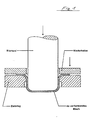
- FIG. 1 explains where there is very good lubrication and where there is no lubricant.
- good lubrication is required to deform the sheet in the area of the inside of the drawing ring and sheet metal, while that in the area of the stamp base is undesirable.
- no lubrication is required in the area outside the points to be deformed.
- Deep drawing plays an important role in body construction, for example. It is state of the art that deep-drawn and stretch-drawn body parts are assembled directly to a body-in-white without intermediate cleaning. The assembly is carried out both by welding and gluing. For both processes, residues of drawing greases are of great disadvantage. Among other things, drawing greases are required to be compatible with the adhesive. However, this requirement is often difficult to meet given the large number of available adhesives. Remaining excess lubricant leads to a further disadvantage, namely the dissolution of drawing agent in the paint bath, which is used to paint the body. This results in an incorrect painting.
- Lubricants such as graphite, certain pigments, talc, chalk, molybdenum sulfide, boric acid, lime, glass powder, etc., which may be present in powder form or as a suspension in various carrier liquids, are also used for deformation processes in the temperature range above 1000 ° C. These agents serve both as lubricants and as release agents and are sprayed onto the area to be deformed and its surroundings, as already described above, according to the prior art. Due to the high temperature, part of the forming lubricant is evaporated and reaches the work area as an emission. Here too there is a need for a method which eliminates the disadvantages of the prior art.
- a method which represents a satisfactory solution to the described problem, namely a method for the quantitative and locally selective application of lubricants to solid bodies, according to which the lubricant is in liquid, atomized or solid form. applies powdery form to the solid body using an electrostatic field, characterized in that the areas of the solid body to be treated with the lubricant are limited in time and location, exposed to an electrostatic field and / or a change in an electrostatic field.
- the lubricant can be applied using known electrostatically operating devices.
- a spraying device can be used in which the solid or liquid lubricant to be applied is electrically charged and applied to a body on which an opposite charge is produced locally and for a limited time, so that the lubricant is only retained in the area of the charge.
- excess lubricant can be removed from the application device immediately after the application of the lubricant. aspirated and reused. After passing through the application device, the body can now be sent for further processing, e.g. deep-drawing and stretch-drawing, with lubricant now only available at the points where it is needed.
- the metering used makes it possible to apply a uniform lubricant coating in the desired thickness at the desired points.
- the desired coating can also be carried out according to the invention by applying an electrostatic field of the required strength, limited in space and quantity, with largely avoiding emissions.
- Electrostatic feeders can also be located on multiple locations or sides of the body that is to be lubricated. It is essential that the areas of the body to be treated with the lubricant are exposed to an electric field and / or a change in an electrostatic field, for a limited time and place.
- a method as described in DE-OS 28 41400 can also be used according to the invention, for example, under the conditions mentioned. Localized coatings can, however, also be applied by inserting shutters.
- the lubricants are generally solid lubricants, such as. e.g. Paraffins, further waxes, e.g. Ester, amide, ether wax, montan wax, etc., chlorinated paraffins, higher-boiling organic acids, alcohols, ketones, etc., as well as polyisobutenes, silicones, animal, etc. Vegetable fats, synthetic fats, etc., also organic or inorganic pigments, boric acid, lime, talc, chalk, organic and inorganic polymers, molybdenum sulfide, graphite, glass, etc., these solids preferably being used as powders. However, the solids can also e.g. in the form of suspensions.
- the lubricants may also contain additives such as e.g. Corrosion protection agents, inhibitors, etc.
- the lubricants can also be liquid lubricants enclosed in microcapsules.
- the lubricants can also be liquid, and consist, for example, of hydrocarbons, as well as silicone oils, animal and vegetable oils, synthetic oils, liquid waxes and others.
- lubricants mentioned are examples, but are not to be considered as limiting.
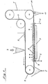
- a material layer corresponding to the charge of the carrier tape remains on the Carrier tape. This can be divided into segments by dividers (4) in order to create zones of different charges and to separate them from one another.
- a sheet (7) to be coated selectively with lubricant locally and in quantity moves perpendicular to the direction of movement of the carrier tape.
- Discharge elements (6) are located above the carrier tape.
- the plate is switched as a counter pole by means of opposing pole brushes (8).
- an electrostatic field can be selectively generated or changed locally, which leads to lubricant reaching the sheet metal at these points from the carrier strip.
- both the carrier tape and the sheet can basically move during the application, the control of the discharge elements (6) having to be adapted accordingly.
- the standstill cycles are generally between 0.1 and 30 seconds, preferably between 0.5 and 10 seconds.
- the electrostatic field can be generated both by direct current and by alternating current.
- the voltage to be applied must be varied according to the distance between the carrier tape and the sheet metal, the amount of lubricant to be applied and the type of carrier tape material.
- Carrier belt speed and layer thickness on the carrier belt must be adapted to the lubricant layer thickness on the sheet to be coated.
- a voltage of 4000 volts was set for a sheet metal coating, with a distance between the sheet metal and the carrier tape of 1 mm.
- Corresponding clamping devices and guide aids can also be used to selectively coat curved sheets or bodies with lubricant locally and in terms of quantity.
- Another embodiment is the coating with spray electrode elements instead of the capacitor plates shown in FIG. 2.
- Electrostatically operating spray guns or certain grids can also be used according to the invention instead of the carrier tape shown in FIG.
- the described deficiencies of the prior art can be overcome for the first time in the lubricant area, in particular in the cold and hot deformation area.
Landscapes
- Engineering & Computer Science (AREA)
- General Engineering & Computer Science (AREA)
- Mechanical Engineering (AREA)
- Application Of Or Painting With Fluid Materials (AREA)
- Lubricants (AREA)
Description
- Die vorliegende Erfindung betrifft ein Verfahren zum mengen-mäßig und örtlich selektiven Beschichten fester Körper mit Schmierstoffen durch Anwendung elektrostatischer Verfahren.
- Das Beschichten durch elektrostatische Verfahren ist bekannt. Es sind zahlreiche Verfahren beschrieben worden, nach denen Farb-, Lack-, Kunststoff- und andere Beschichtungen mittels elektrostatischer Felder aufgebracht werden können.
- So wird in DE-OS 28 04 633 eine Vorrichtung zum elektrostatischen Aufbringen einer flüssigen Farbe beschrieben, wobei Schaum- und Bläschenbildung in der aufgebrachten Farbschicht vermieden werden sollen.
- In DE-OS 28 41 400 wird ein Verfahren beschrieben, um eine Kunststoffbeschichtung im elektrostatischen Feld in dünner gleichmäßiger Schicht auf einem Körper aufzubringen. Hierzu wird ein auf einem Träger befindlicher geschmolzener Kunststoff an einem zu beschichtenden Körper im elektrostatischen Feld vorbeigeführt, wobei sich der flüssige Kunststoff auf dem Körper ablagert.
- Auch das elektrostatische Aufbringen flüssiger, organischer Schmierstoffe ist bereits beschrieben worden.
- So kann man nach der Offenbarung der DE-OS 24 33 006, die dem Oberbegriff des Hauptanspruchs der vorliegenden Erfindung zugrunde liegt, einen elektrisch aufgeladenen Flüssigkeitsnebel eines Schmierstoffs in einer elektrostatischen Kammer auf einem Blech, einem Metallband oder einer Metallplatte abscheiden. Bei diesem Verfahren ist zwar eine mengenmässige Dosierung in gewissem Umfang möglich, jedoch wird die gesamte in der Kammer befindliche Metallfläche von dem angewendeten Schmiermittel bedeckt.
- In DE-OS 27 32 009 wird ein Verfahren beschrieben, um für Verpackungszwecke Feinstblech mit einer physiologisch unbedenklichen, dünnen, schützenden Schicht zu bedecken. Hierbei wird das Blech in Bandform bei einer bestimmten Bandgeschwindigkeit elektrostatisch beschichtet. Auch bei diesem Verfahren erfolgt die Beschichtung der gesamten Bandfläche.
- Über den geschilderten Stand der Technik hinaus besteht in zahlreichen Technologien, in denen eine Schmierung der zu verarbeitenden festen Körper erforderlich ist, ein Bedürfnis des Fachmanns, nicht nur Oberflächenbeschichtungen in fein verteilter, gleichmäßiger Schicht, sondern eine solche Beschichtung auch örtlich begrenzt vornehmen zu können, nämlich nur an den Stellen, an denen die Schmierung tatsächlich erforderlich ist. Nach dem Stand der Technik verwendet man zum örtlich begrenzten Aufbringen von Schmiermitteln übliche nicht elektrostatisch arbeitende Schmiermittelpistolen, welche an bestimmten Stellen zu bestimmten Zeitpunkten eine nicht genau dosierbare Schmiermittelmenge auf den zu schmierenden Körper abgeben. Das Schmiermittel wird hierbei punktförmig aufgebracht oder auf einen in der Größe nicht eakt eingrenzbaren Bereich aufgesprüht. Mit diesen Maßnahmen sind erhebliche Mängel verbunden, wie z.B. das Vorliegen des Schmiermittels in Bereichen, auf denen dieses unerwünscht oder von Nachteil ist, wobei gegebenenfalls das Schmiermittel von diesen Stellen vorderWeiterverarbeitung durch Reinigen mit Lösungsmitteln wieder entfernt werden muß. Nachteilig ist ferner ein zu großer Verbrauch an Schmiermitteln, die Emission des Schmiermittels in den Arbeitsraum, verbunden mit entsprechender Umweltbelastung, oder Verschmierungen und Verharzungen des nicht entfernbaren überschüssigen Schmiermittels, welche die Weiterverarbeitung der zu schmierenden Körper erschweren.
- Die geschilderten Schwierigkeiten treten insbesondere in technischen Bereichen auf, in denen Schmiermittel als Ziehmittel z.B. beim Tief- und Streckziehen oder als Umformschmierstoffe, z.B. beim Schmieden, Kaltfließpressen, Drahtziehen und Rohrwalzen eingesetzt werden.
- Figur 1 stellt als Beispiel einen zu schmierenden Tiefziehvorgang dar.
- Figur 2 stellt ein Beispiel einer erfindungsgemäßen örtlich und zeitlich begrenzten Schmierung eines ebenen Bleches dar.
- In Figur 1 ist erläutert, wo räumlich begrenzt eine sehr gute Schmierung und wo kein Schmiermittel vorliegen soll. So ist im Bereich von Ziehringinnenseite und Blech eine gute Schmierung zur Verformung des Bleches erforderlich, während eine solche im Bereich des Stempelbodens unerwünscht ist. Natürlich wird auch keine Schmierung im Bereich außerhalb der zu verformenden Stellen benötigt. Das Tiefziehen spielt eine bedeutende Rolle beispielsweise im Karosseriebau. Es ist Stand der Technik, daß tiefgezogene und streckgezogene Karosserieteile ohne zwischengeschaltete Reinigung direktzuRohkarosserie zusammengebaut werden. Der Zusammenbau erfolgt sowohl durch Schweißen als auch Kleben. Für beide Verarbeitungen sind Reste von Ziehfetten von großem Nachteil. An Ziehfette wird daher unter anderem die Forderung der Verträglichkeit mit dem Kleber gestellt. Diese Forderung ist jedoch bei der Vielzahl vorhandener Kleber häufig schwer zu erfüllen. Verbleibendes überschüssiges Schm-eirmittel führt zu einem weiteren Nachteil, nämlich zur Auflösung von Ziehmittel im Lackbad, das zur Lackierung der Karosserie dient. Dies hat eine nicht einwandfreie Lackierung zur Folge.
- Figur 1 macht deutlich, daß ein großes Bedürfnis für ein Losung der Aufgabenstellung besteht, Schmierstoffe nicht nur in der erforderlichen dünnen Schicht und gleichmäßigen Verteilung, sondern auch in der erforderlichen räumlichen Begrenzung auf feste, weiter zu verarbeitende Körper aufzubringen. Obgleich gerade in der metallverarbeitenden Industrie, insbesondere im Autobau weltweit in riesigem Umfang Verformungen mit Hilfe von Ziehmitteln vorgenommen werden, steht zu Zeit noch keine befriedigende Lösung der genannten Aufgabe zu Verfügung.
- Auf einem eiteren Gebiet ist die oben genannte Aufgabe ebenfalls nicht zufriedenstellend gelöst, nämlich im Bereich von in heißem Zustand um oder zu verformenden Gegenständen. Auch bei Verformungsvorgängen im Temperaturbereich von über 1000°C werden Schmiermittel eingesetzt, wie z.B. Graphit, gewisse Pigmente, Talkum, Kreide, Molybdänsulfid, Borsäure, Kalk, Glaspulver u.a. die ggfs. in Pulverform oder als Suspension in verschiedenen Trägerflüssigkeiten vorliegen können. Diese Mittel dienen sowohl als Schmier- als auch als Trennmittel und werden nach dem Stand der Technik auf die zu verformende Stelle und deren Umgebung - wie bereits oben beschrieben - aufgesprüht. Durch die hohe Temperatur wird ein Teil des Umformschmierstoffs verdampft und gelangt in den Arbeitsraum als Emission. Auch hier besteht ein Bedürfnis nach einem Verfahren, das die Nachteile des Standes der Technik ausschaltet.
- Gemäß vorliegender Erfindung wird nunmehr ein Verfahren zur Verfügung gestellt, daß eine befriedigende Lösung der geschilderten Aufgabe darstellt, nämlich ein Verfahren zum mengen- mäßig und örtlich selektiven Aufbringen von Schmiermitteln auf feste Körper, gemäss dem man das Schmiermittel in flüssiger, zerstäubter Form oder fester, pulverförmiger Form unter Verwendung eines elektrostatischen Feldes auf den festen Körper aufbringt, dadurch gekennzeichnet, dass die mit dem Schmiermittel zu behandelnden Stellen des festen Körpers zeitlich und örtlich begrenzt, einem elektrostatischen Feld und/oder einer Änderung eines elektrostatischen Feldes ausgesetzt werden.
- Im Rahmen der vorliegenden Erfindung kann das Schmiermittel mit an sich bekannten elektrostatisch arbeitenden Vorrichtungen aufgebracht werden. So kann eine Spritzvorrichtung eingesetzt werden, in der das aufzubringende feste oder flüssige Schmiermittel elektrisch aufgeladen wird und auf einen Körper aufgebracht wird auf dem örtlich und zeitlich begrenzt eine entgegengesetzte Ladung hervorgebracht wird, so daß nur im Bereich der Ladung das Schmiermittel festgehalten wird.
- Nach dem Einsatz eines räumlich begrenzten elektrischen Feldes kann erfindungsgemäß unmittelbar nach dem Aufbringen des Schmiermittels überschüssiges Schmiermittel von der Aufgabevorrichtung. abgesaugt und der Wiederverwendung zugeführt werden. Nach Durchlaufen der Aufbringvorrichtung kann nunmehr der Körper der Weiterverarbeitung zugeführt werden, z.B. dem Tief- und Streckziehen, wobei nunmehr nur an den Stellen Schmiermittel vorhanden ist, an denen es benötigt wird. Durch die angewendete Dosierung läßt sich an den gewünschten Stellen eine gleichmäßige Schmiermittelbeschichtung aufbringen in der gewünschten Dicke.
- Auch im Falle der heißen Verformung kann erfindungsgemäß ebenfalls durch Anlegen eines elektrostatischen Feldes in der erforderlichen Stärke, räumlich und mengenmäßig begrenzt, unter weitgehender Vermeidung von Emissionen die gewünschte Beschichtung vorgenommen werden.
- Elektrostatische Aufgabevorrichtungen können sich auch an mehreren Stellen bzw. Seiten des Körpers befinden, der mit Schmiermittel zu behandeln ist. Wesentlich ist, daß die mit dem Schmiermittel zu behandelnden Stellen des Körpers, örtlich und zeitlich begrenzt, einem elektrischen Feld und/oder einer Anderung eines elektrostatischen Feldes ausgesetzt werden. Auch ein Verfahren, wie es in der DE-OS 28 41400 beschrieben ist, kann beispielsweise unter den genannten Vorraussetzungen erfindungsgemäß angewandt werden. Örtlich begrenzte Beschichtungen können jedoch auch durch Vorschalten von Blenden vorgenommen werden.
- Die geschilderten Verfahren sind beispielhaft, jedoch nicht als einschränkend anzusehen.
- Als zu beschichtende Körper seien beispielhaft, jedoch nicht einschränkend genannt:
- Bleche, Platten, wobei diese beispielsweise in Form von Folien und Bändern, jedoch auch in vorgestanzter Form vorliegen können, Karosserieteile, Drähte, Blöcke, sonstige Körper, Behälter, Rohre, Töpfe, Bestecke u.a. Die Körper können aus Metallen angefertigt sein, jedoch auch beispielsweise aus Kunststoffen.
- Bei den Schmierstoffen handelt es sich erfindungsgemäß im allgemeinen um feste Schmierstoffe, wie. z.B. Paraffine, ferner Wachse, wie z.B. Ester-, Amid-, Etherwachs, Montanwachs u.a., Chlorparaffine, höher siedende organische Säuren, Alkohole, Ketone u.a., ferner Polyisobutene, Silicone, tierische u. pflanzliche Fette, synthetische Fette u.a., ferner organische oder anorganische Pigmente, Borsäure, Kalk, Talkum, Kreide, organische und anorganische polymere, Molybdänsulfid, Graphit, Glas u.a., wobei diese Feststoffe bevorzugt als Pulver angewendet werden. Die Feststoffe können jedoch auch z.B. in Form von Suspensionen angewendet werden. Ferner können die Schmiermittel Zusätze enthalten, wie z.B. Korrosionsschutzmittel, Inhibitoren u.a.
- Die Schmierstoffe können jedoch auch in Mikrokapseln eingeschlossene flüssige Schmierstoffe sein.
- Die Schmierstoffe können jedoch auch flüssig sein, und beispielsweise aus Konlenwasserstoffen bestehen, ferner aus Siliconölen, tierischen und pflanzlichen Ölen, synthetischen Ölen, Flüssigwachsen u.a.
- Die genannten Schmiermittel sind beispielhaft, jedoch nicht limitierend anzusehen.
- Mit Hilfe der Figur 2 soll beispielhaft das erfindungsgemäße Verfahren näher erläutert werden.
- Ein Trägerband (1) aus elektrostatisch gut aufladbarem Kunststoff, beispielsweise einer Folie oder einem Gewebe, wird bei Vorrichtung (2) elektrostatisch aufgeladen. Anschließend wird bei (3) pulverförmiges oder granulatförmiges Schmiermittel aufgegeben.
- Überschüssiges Schmiermittel fällt an der ersten Umlenkrolle des Trägerbandes ab und wird über Auffangund Rückfördereinheit (5) zurückgewonnen.
- Es verbleibt eine der Aufladung des Trägerbandes entsprechend starke Materialschicht auf dem Trägerband. Dieses kann durch Trennstücke (4) in Segmente unterteilt werden, um Zonen unterschiedlicher Ladung zu erzeugen und diese voneinander zu trennen.
- Senkrecht zur Bewegungsrichtung des Trägerbandes bewegt sich ein mit Schmiermittel örtlich und mengenmäßig selektiv zu beschichtendes Blech (7). Oberhalb des Trägerbandes befinden sich Entladungselemente (6). Das Blech ist durch Gegenpolbrüsten (8) als Gegenpol geschaltet. Durch entsprechende Umpolung der einzelnen Entladungselemente kann örtlich selektiv ein elektrostatisches Feld erzeugt oder geändert werden, das dazu führt, daß an diesen Stellen Schmiermittel von dem Trägerband auf das Blech gelangt.
- Überschüssiges Pulver kann an Vorrichtung (11) abgestreift werden. (9) stellt eine Blechtransporteinheit dar.
- Im allgemeinen kommt das Blech während des Aufbringtaktes zum Stillstand. Es können sich jedoch sowohl das Trägerband als auch das Blech grundsätzlich während des Aufbringens bewegen, wobei die Steuerung der Entladungselemente (6) entsprechend angepasst sein muß.
- Die Stillstandtakte liegen im allgemeinen zwischen 0,1 bis 30 sec., vorzugsweise zwischen 0,5 bis 10 sec.
- Das elektrostatische Feld kann erfindungsgemäß sowohl durch Gleichstrom als auch durch Wechselstrom erzeugt werden. Die anzulegende Spannung muß entsprechend dem Abstand zwischen Trägerband und Blech, aufzubringender Schmiermittelmenge und Art des Trägerbandmaterials variiert werden. Trägerbandgeschwindigkeit und Schichtdicke auf dem Trägerband sind dem Bedarf an Schmiermittel-Schichtdicke auf dem zu beschichtenden Blech anzupassen.
- Beispielhaft wurde bei einer Blechbeschichtung eine Spannung von 4000 Volt eingestellt, bei einem Abstand zwischen Blech und Trägerband von 1 mm.
- Durch entsprechende Spannvorrichtungen und Führungshilfen können auch gewölbte Bleche oder Körper, mit Schmiermittel örtlich und mengenmäßig selektiv beschichtet werden.
- Ein weiteres Ausführungsbeispiel ist die Beschichtung mit Sprühelektrodenelementen anstelle der in Figur 2 dargestellten Kondensatorplatten.
- Auch elektrostatisch arbeitende Spritzpistolen oder bestimmte Raster können anstelle des in Figur 2 dargestellen Trägerbandes erfindungsgemäß eingesetzt werden.
- Durch das erfindungsgemäße Verfahren können erstmals im Schmiermittelbereich, insbesondere im Kalt- und Heißverformungsbereich die geschilderten Mängel des Standes der Technik überwunden werden.
Claims (6)
Priority Applications (1)
| Application Number | Priority Date | Filing Date | Title |
|---|---|---|---|
| AT86106571T ATE59586T1 (de) | 1985-05-15 | 1986-05-14 | Verfahren zum beschichten fester koerper mit schmiermitteln. |
Applications Claiming Priority (2)
| Application Number | Priority Date | Filing Date | Title |
|---|---|---|---|
| DE19853517553 DE3517553A1 (de) | 1985-05-15 | 1985-05-15 | Verfahren zum beschichten fester koerper mit schmiermitteln |
| DE3517553 | 1985-05-15 |
Publications (3)
| Publication Number | Publication Date |
|---|---|
| EP0201923A2 EP0201923A2 (de) | 1986-11-20 |
| EP0201923A3 EP0201923A3 (en) | 1988-01-27 |
| EP0201923B1 true EP0201923B1 (de) | 1991-01-02 |
Family
ID=6270831
Family Applications (1)
| Application Number | Title | Priority Date | Filing Date |
|---|---|---|---|
| EP19860106571 Expired - Lifetime EP0201923B1 (de) | 1985-05-15 | 1986-05-14 | Verfahren zum Beschichten fester Körper mit Schmiermitteln |
Country Status (3)
| Country | Link |
|---|---|
| EP (1) | EP0201923B1 (de) |
| AT (1) | ATE59586T1 (de) |
| DE (2) | DE3517553A1 (de) |
Families Citing this family (6)
| Publication number | Priority date | Publication date | Assignee | Title |
|---|---|---|---|---|
| US4692988A (en) * | 1986-08-19 | 1987-09-15 | Nowsco Well Service (U.K.) Limited | Screw thread protection |
| DE59009959D1 (de) * | 1989-05-31 | 1996-01-25 | Sfb Spezialfilter Und Anlagenb | Anlage und Verfahren zur Herstellung von pulverbeschicheten, flachen Teilen, insbesondere flachen Blechteilen |
| JPH0350298A (ja) * | 1989-06-16 | 1991-03-04 | Castrol Ind Inc | キャリアー―フリー鍛造用潤滑剤およびその使用方法 |
| DE4017362A1 (de) * | 1989-12-23 | 1991-06-27 | Columbus System Patent Ag | Verfahren zur vorbehandlung von blech |
| DE4313752A1 (de) * | 1993-04-27 | 1994-11-03 | Karl Naumann Gmbh | Verfahren zur formgebenden Bearbeitung von Metallteilen mit anschließender Lackierung |
| EP2298456A1 (de) | 2009-09-10 | 2011-03-23 | Bharat Forge Aluminiumtechnik GMBH & CO. KG | Verfahren zum Schmiermittelauftrag auf Schmiedematerial |
Family Cites Families (5)
| Publication number | Priority date | Publication date | Assignee | Title |
|---|---|---|---|---|
| US2297691A (en) * | 1939-04-04 | 1942-10-06 | Chester F Carlson | Electrophotography |
| AU473798B2 (en) * | 1973-07-26 | 1976-07-01 | Ball Corporation | Method and apparatus for applying lubricating materials to metallic substrates |
| AU517923B2 (en) * | 1977-02-07 | 1981-09-03 | Ransburg Japan Ltd. | Rotary paint atomizing device |
| DE2732009C3 (de) * | 1977-07-15 | 1982-03-25 | Estel Hoesch Werke Ag, 4600 Dortmund | Verfahren zum elektrostatischen Aufbringen einer ölhaltigen Oberflächenschutzschicht auf bandförmiges Feinstblech |
| SE7809653L (sv) * | 1977-09-23 | 1979-03-24 | Scal Gp Condit Aluminium | Beleggning av plastmaterial |
-
1985
- 1985-05-15 DE DE19853517553 patent/DE3517553A1/de active Granted
-
1986
- 1986-05-14 EP EP19860106571 patent/EP0201923B1/de not_active Expired - Lifetime
- 1986-05-14 DE DE8686106571T patent/DE3676340D1/de not_active Expired - Fee Related
- 1986-05-14 AT AT86106571T patent/ATE59586T1/de not_active IP Right Cessation
Also Published As
| Publication number | Publication date |
|---|---|
| DE3676340D1 (de) | 1991-02-07 |
| EP0201923A2 (de) | 1986-11-20 |
| DE3517553A1 (de) | 1986-11-20 |
| ATE59586T1 (de) | 1991-01-15 |
| DE3517553C2 (de) | 1989-06-29 |
| EP0201923A3 (en) | 1988-01-27 |
Similar Documents
| Publication | Publication Date | Title |
|---|---|---|
| DE2750372A1 (de) | Elektrostatisches beschichtungsverfahren | |
| DE3440381A1 (de) | Verfahren und vorrichtung zum automatischen elektrostatischen spruehbeschichten | |
| EP0675770A1 (de) | Verfahren und vorrichtung zum aufbringen einer schmierstoffträgerschicht insbesondere auf ein im ziehverfahren zu verformendes drahtmaterial | |
| DE3606678C2 (de) | Kabine für die elektrostatische Pulverlackierung | |
| EP0201923B1 (de) | Verfahren zum Beschichten fester Körper mit Schmiermitteln | |
| WO1986001747A1 (en) | Method for applying solid suspensions capable of being fired on ceramic or glass substrates, and device for implementing such method | |
| DE10115087A1 (de) | Verfahren und Vorrichtung zum Beschichten eines Kunststoffbehälters | |
| WO2000038874A1 (de) | Verfahren zur partiellen oder vollständigen beschichtung der oberflächen von bauteilen aus aluminium und seinen legierungen mit lot, fluss- und bindemittel zur hartverlötung | |
| DE2704302A1 (de) | Metalltube und verfahren und vorrichtung zum erzeugen einer oberflaechenpulverschicht auf der metalltube | |
| EP1321197A2 (de) | Verfahren und Vorrichtung zur Beschichtung von bewegten Substraten | |
| EP2512697B1 (de) | Verfahren zum entfernen von überschüssigem klebstoff | |
| EP1186361A2 (de) | Verfahren zum Schmieren von Umform- und Urformwerkzeugen, von Formen zum Druck-, Automatik- und Stranggiessen und Brikettieren, insbesondere zum Schmieren von Warmschmiedewerkzeugen, und Vorrichtung zum Durchführen des Verfahrens | |
| EP2055809A2 (de) | Verfahren und Vorrichtung zum Erzeugen einer Konversionsschicht | |
| DE102018115622A1 (de) | Verbindungsverfahren für Karosseriedichtungselemente | |
| DE1671527C3 (de) | Verfahren und Vorrichtung zum elektrostatischen Bedrucken einer Unterlage geringer elektrischer Leitfähigkeit | |
| DE2030595A1 (de) | Verfahren und Vorrichtung zum Beschichten von Bandmaterialien mit pulverförmigen Überzugsmitteln | |
| DE2433006A1 (de) | Verfahren und vorrichtung zum aufbringen eines schmiermittels auf ein metallsubstrat | |
| DE102018110496A1 (de) | Verbindungsverfahren für Karosseriedichtungselemente | |
| DE2633179A1 (de) | Verfahren und vorrichtung zum elektrophoretischen beschichten | |
| EP1949969B1 (de) | Lackiereinrichtung | |
| DE102022113575B4 (de) | Beschichtungsvorrichtung und Verfahren zum Beschichten eines flächigen Werkstückes mit der Beschichtungsvorrichtung | |
| DE19625789B4 (de) | Verfahren zum Beschichten einer Karosserie | |
| EP3713747B1 (de) | Verbindungsverfahren für karosseriedichtungselemente | |
| DE10250471B3 (de) | Anlage zur Antikorrosionsbehandlung von Ventiltellern für Spenderbehälter | |
| DE3015969C2 (de) | Vorrichtung zum Schmieren eines Werkzeuges, insbesondere einer Schmiedepresse |
Legal Events
| Date | Code | Title | Description |
|---|---|---|---|
| PUAI | Public reference made under article 153(3) epc to a published international application that has entered the european phase |
Free format text: ORIGINAL CODE: 0009012 |
|
| 17P | Request for examination filed |
Effective date: 19860514 |
|
| AK | Designated contracting states |
Kind code of ref document: A2 Designated state(s): AT BE CH DE FR GB IT LI LU NL SE |
|
| PUAL | Search report despatched |
Free format text: ORIGINAL CODE: 0009013 |
|
| AK | Designated contracting states |
Kind code of ref document: A3 Designated state(s): AT BE CH DE FR GB IT LI LU NL SE |
|
| 17Q | First examination report despatched |
Effective date: 19890209 |
|
| GRAA | (expected) grant |
Free format text: ORIGINAL CODE: 0009210 |
|
| AK | Designated contracting states |
Kind code of ref document: B1 Designated state(s): AT BE CH DE FR GB IT LI LU NL SE |
|
| REF | Corresponds to: |
Ref document number: 59586 Country of ref document: AT Date of ref document: 19910115 Kind code of ref document: T |
|
| REF | Corresponds to: |
Ref document number: 3676340 Country of ref document: DE Date of ref document: 19910207 |
|
| ITF | It: translation for a ep patent filed | ||
| GBT | Gb: translation of ep patent filed (gb section 77(6)(a)/1977) | ||
| ET | Fr: translation filed | ||
| PGFP | Annual fee paid to national office [announced via postgrant information from national office to epo] |
Ref country code: GB Payment date: 19910513 Year of fee payment: 6 |
|
| PG25 | Lapsed in a contracting state [announced via postgrant information from national office to epo] |
Ref country code: AT Effective date: 19910514 |
|
| PG25 | Lapsed in a contracting state [announced via postgrant information from national office to epo] |
Ref country code: LU Free format text: LAPSE BECAUSE OF NON-PAYMENT OF DUE FEES Effective date: 19910531 |
|
| PGFP | Annual fee paid to national office [announced via postgrant information from national office to epo] |
Ref country code: SE Payment date: 19910531 Year of fee payment: 6 Ref country code: NL Payment date: 19910531 Year of fee payment: 6 |
|
| PGFP | Annual fee paid to national office [announced via postgrant information from national office to epo] |
Ref country code: FR Payment date: 19910607 Year of fee payment: 6 |
|
| PGFP | Annual fee paid to national office [announced via postgrant information from national office to epo] |
Ref country code: BE Payment date: 19910612 Year of fee payment: 6 |
|
| PGFP | Annual fee paid to national office [announced via postgrant information from national office to epo] |
Ref country code: CH Payment date: 19910819 Year of fee payment: 6 |
|
| PLBE | No opposition filed within time limit |
Free format text: ORIGINAL CODE: 0009261 |
|
| STAA | Information on the status of an ep patent application or granted ep patent |
Free format text: STATUS: NO OPPOSITION FILED WITHIN TIME LIMIT |
|
| 26N | No opposition filed | ||
| PG25 | Lapsed in a contracting state [announced via postgrant information from national office to epo] |
Ref country code: GB Effective date: 19920514 |
|
| PG25 | Lapsed in a contracting state [announced via postgrant information from national office to epo] |
Ref country code: SE Effective date: 19920515 |
|
| PG25 | Lapsed in a contracting state [announced via postgrant information from national office to epo] |
Ref country code: LI Effective date: 19920531 Ref country code: CH Effective date: 19920531 Ref country code: BE Effective date: 19920531 |
|
| PG25 | Lapsed in a contracting state [announced via postgrant information from national office to epo] |
Ref country code: DE Effective date: 19920602 |
|
| BERE | Be: lapsed |
Owner name: LICHTENBERG & CO. CHEMISCHE FABRIK ZWEIGNIEDERLAS Effective date: 19920531 |
|
| PG25 | Lapsed in a contracting state [announced via postgrant information from national office to epo] |
Ref country code: NL Effective date: 19921201 |
|
| GBPC | Gb: european patent ceased through non-payment of renewal fee |
Effective date: 19920514 |
|
| NLV4 | Nl: lapsed or anulled due to non-payment of the annual fee | ||
| PG25 | Lapsed in a contracting state [announced via postgrant information from national office to epo] |
Ref country code: FR Effective date: 19930129 |
|
| REG | Reference to a national code |
Ref country code: CH Ref legal event code: PL |
|
| REG | Reference to a national code |
Ref country code: FR Ref legal event code: ST |
|
| EUG | Se: european patent has lapsed |
Ref document number: 86106571.2 Effective date: 19921204 |
|
| PG25 | Lapsed in a contracting state [announced via postgrant information from national office to epo] |
Ref country code: IT Free format text: LAPSE BECAUSE OF NON-PAYMENT OF DUE FEES;WARNING: LAPSES OF ITALIAN PATENTS WITH EFFECTIVE DATE BEFORE 2007 MAY HAVE OCCURRED AT ANY TIME BEFORE 2007. THE CORRECT EFFECTIVE DATE MAY BE DIFFERENT FROM THE ONE RECORDED. Effective date: 20050514 |