EP0201936B1 - Element zur Erfassung von Kohlendioxidgas und Verfahren zur Herstellung des Elements - Google Patents
Element zur Erfassung von Kohlendioxidgas und Verfahren zur Herstellung des Elements Download PDFInfo
- Publication number
- EP0201936B1 EP0201936B1 EP86106730A EP86106730A EP0201936B1 EP 0201936 B1 EP0201936 B1 EP 0201936B1 EP 86106730 A EP86106730 A EP 86106730A EP 86106730 A EP86106730 A EP 86106730A EP 0201936 B1 EP0201936 B1 EP 0201936B1
- Authority
- EP
- European Patent Office
- Prior art keywords
- carbon dioxide
- hydroxyapatite
- dioxide gas
- detection element
- electrical resistance
- Prior art date
- Legal status (The legal status is an assumption and is not a legal conclusion. Google has not performed a legal analysis and makes no representation as to the accuracy of the status listed.)
- Expired - Lifetime
Links
Images


Classifications
-
- G—PHYSICS
- G01—MEASURING; TESTING
- G01N—INVESTIGATING OR ANALYSING MATERIALS BY DETERMINING THEIR CHEMICAL OR PHYSICAL PROPERTIES
- G01N33/00—Investigating or analysing materials by specific methods not covered by groups G01N1/00 - G01N31/00
- G01N33/0004—Gaseous mixtures, e.g. polluted air
- G01N33/0009—General constructional details of gas analysers, e.g. portable test equipment
- G01N33/0027—General constructional details of gas analysers, e.g. portable test equipment concerning the detector
- G01N33/0036—General constructional details of gas analysers, e.g. portable test equipment concerning the detector specially adapted to detect a particular component
- G01N33/004—CO or CO2
-
- G—PHYSICS
- G01—MEASURING; TESTING
- G01N—INVESTIGATING OR ANALYSING MATERIALS BY DETERMINING THEIR CHEMICAL OR PHYSICAL PROPERTIES
- G01N27/00—Investigating or analysing materials by the use of electric, electrochemical, or magnetic means
- G01N27/02—Investigating or analysing materials by the use of electric, electrochemical, or magnetic means by investigating impedance
- G01N27/04—Investigating or analysing materials by the use of electric, electrochemical, or magnetic means by investigating impedance by investigating resistance
- G01N27/12—Investigating or analysing materials by the use of electric, electrochemical, or magnetic means by investigating impedance by investigating resistance of a solid body in dependence upon absorption of a fluid; of a solid body in dependence upon reaction with a fluid, for detecting components in the fluid
-
- Y—GENERAL TAGGING OF NEW TECHNOLOGICAL DEVELOPMENTS; GENERAL TAGGING OF CROSS-SECTIONAL TECHNOLOGIES SPANNING OVER SEVERAL SECTIONS OF THE IPC; TECHNICAL SUBJECTS COVERED BY FORMER USPC CROSS-REFERENCE ART COLLECTIONS [XRACs] AND DIGESTS
- Y10—TECHNICAL SUBJECTS COVERED BY FORMER USPC
- Y10T—TECHNICAL SUBJECTS COVERED BY FORMER US CLASSIFICATION
- Y10T436/00—Chemistry: analytical and immunological testing
- Y10T436/20—Oxygen containing
- Y10T436/204998—Inorganic carbon compounds
Definitions
- the present invention relates to an element for detecting carbon dioxide gas, and a process for producing the same.
- the present invention can be utilized in various fields, such as, for example, for the control of the concentration of carbon dioxide gas in a hothouse for agricultural cultivation (agricultural use), for the monitoring of exhaust gases (industrial use), for the control of living environments (use for environmental sanitation), for the early detection of fires (use for the prevention of disasters), and the like.
- a method utilizing the characteristic absorption of carbon dioxide gas in the infrared region of the spectrum consists of an IR ray Generation section from which an IR beam with a wavelength of 4.25 ⁇ m, is emitted, a cell having a path length of several meters, an IR detector, and a fan which draws air through the cell.
- An apparatus utilizing the method therefore, is expensive and could hardly be small in size.
- measurements utilising the method are susceptible to the influence of dusts and other contaminants.
- FR-A-2383440 discloses that the products of a combustion reaction, including carbon dioxide, may in general be detected by virtue of their effect on the electrical resistance of a porphyrin semiconductor substrate.
- US-A-4157378 discloses a process for producing fluorapatite by reacting dicalcium phosphate dihydrate with hydrogen fluoride in an aqueous solution.
- the fluorapatite obtained is used as part of a dental preparation.
- DE-A-2724972 discloses a sintered apatite body having increased mechanical strength for use as a prosthetic tooth or bone. This is formed by calcining of a calcium compound, a magnesium compound and an amorphous apatite. In the calcining process, the apatite powder and the magnesium containing compound react chemically with each other producing an end product which is different from the initial formulation.
- a hydroxyapatite which so far is known to be a porous ceramic usable as a moisture sensor since its electrical resistance changes in response to the change in moisture (see Japanese Patent Application (OPI) No. 166,249/83).
- OPI Japanese Patent Application
- the moisture sensor of a hydroxyapatite utilises the physical phenomenon that water absorbed on the surface of a hydroxyapatite penetrates into the pores of the porous ceramic and condenses therein.
- the present invention provides a detection element specific for carbon dioxide gas formed from a composite material comprising:
- the present invention provides a process for producing a detection element for carbon dioxide gas comprising immersing a hydroxyapatite into an aqueous solution of an inorganic halide, followed by drying; said hydroxyapatite being represented by formula (I).
- the detection of the presence of carbon dioxide gas can be effected with an increased sensitivity by bringing a carbon dioxide gas detection element comprising a composite of a hydroxy- apatite represented by the above formula (I) and an inorganic carbonate into contact with a gas containing carbon dioxide in order to attain an increased change in its electrical resistance upon contact with carbon dioxide.
- the detection of the presence of carbon dioxide gas can be effected with a much increased sensitivity even at a low temperature by using a carbon dioxide gas detection element which comprises a composite of a hydroxyapatite represented by the above formula (I) and an inorganic halide and bringing it into contact with carbon dioxide in order to enhance the change in its electrical resistance.
- the hydroxyapatite represented by formula (I); wherein M is an element selected from the group consisting of Ca, Ba, Sr, Pb and Cd; and Z is an element selected from the group consisting of P, As and V, may be prepared by known methods, including e.g., wet dry and hydrothermal processes. Any hydroxyapaptite having formula (I) can be used in the present invention. However, it is preferable to use a hydroxyapatite represented by formula (I) wherein M is Ca and Z is P.
- compounds of formula (I) may also contain small amounts of the elements Sc, Y, TI, Bi, V, Ni, Mn, Fe, Sn, Rb, Na, K, and Cs in addition to those elements listed for element M and small amounts of the elements Si, Ge, Cr, Mn, Al, and B in addition those elements listed for element Z.
- a porous sintered material of a hydroxyapatite can be obtained by molding powders of a hydroxyapatite in a mold of, such as a pellet molding machine with the application of pressure and then sintering the molded product in an electric furnace at a temperature of from 800 to 1,000°C, preferably from 850 to 950°C, for a period of 1 hour or more, preferably from 1.5 to 2.5 hours.
- the hydroxyapatite may be mixed with water and an organic binder, e.g., a methyl cellulose, to form a slurry, which can be coated on a refractory substrate or base in the form of a thin layer.
- the coated product may then be sintered at a temperature of from 800 to 1,000°C, preferably from 800 to 950°C, for a period of 1 hour or more, preferably from 1.5 to 2.5 hours.
- the thus prepared porous sintered product can be immersed in an aqueous inorganic carbonate solution and then dried to allow the inorganic carbonate to attach on the surface of the hydroxy- apatite, thereby forming a composite of a hydroxyapatite and an inorganic carbonate according to the invention.
- any inorganic carbonate which increases the variation in electrical resistance due to the contact of the hydroxyapatite with carbon dioxide gas can be used in the present invention. It is preferred to use a sodium carbonate or calcium carbonate.
- a hydroxyapatite-inorganic halide composite material of a carbon dioxide gas detection element according to the invention can be produced by immersing a porous sintered product of a hydroxyapatite in an aqueous inorganic halide solution and drying it to thereby deposit the inorganic halide on a surface of the hydroxy- apatite.
- any inorganic halide which is capable of enhancing the change in the electrical resistance of the hydroxyapatite upon contact with gaseous carbon dioxide. It is, however, preferable to use calcium chloride, ammonium chloride or mixtures thereof.
- a carbon dioxide gas detection element can be produced by providing electrodes and wire leads at the both ends of the material comprising the hydroxyapatite-inorganic carbonate composite or the hydroxyapatite-inorganic halide composite according to the invention.
- a carbon dioxide gas detection element according to the invention can also be produced by providing electrodes and wire leads at both ends of a porous sintered product of a hydraxyapatite and then immersing it in an aqueous inorganic carbonate solution, followed by drying it to form a composite of the hydroxyapatite and the inorganic carbonate.
- a hydroxyapatite-inorganic halide composite material of a carbon dioxide gas detection element can be produced by immersing a porous, sintered product of a hydroxyapatite, which is provided with electrodes and wire leads, in an aqueous inorganic halide solution and drying it to thereby deposit the inorganic halide on a surface of the hydroxyapatite.
- the immersion of the sintered hydroxyapatite into the aqueous solution of an inorganic carbonate or of an inorganic halide may be carried out in two stages: firstly under a reduced pressure, e.g., 1/10 of atmospheric pressure in the first stage, and then at atmospheric pressure in the second stage.
- the inorganic carbonate or the inorganic halide contained in the aqueous solution of the carbonate or the halide can be distributed throughout the pores of the sintered product to form a hydroxyapatite-inorganic carbonate composite or a hydroxyapatite-inorganic halide composite on the entire suface of the hydroxyapatite.
- the amount of the composites formed by the immersion can be increased by using in the immersing treatment an aqueous inorganic carbonate or halide solution containing the carbonate or halide in an increased amount.
- the electrical resistance of the detection element decreases with the increase in the amount of the composite contained therein. This makes the increase in the electrical resistance of the composites observed upon contact with gaseous carbon dioxide greater, i.e., makes the element more sensitive to gaseous carbon dioxide. Accordingly, the presence of carbon dioxide contained in a gas can be detected by the use of the detection element according to the invention even at a relatively low temperature, e.g., at around room temperature.
- the electrical resistance is increased by the presence of carbon dioxide in a gas, but it is slightly decreased when moisture is present in the gas. Accordingly, in order to completely remove the influence by the moisture in the gas, it is required to remove the moisture in the gas in advance, or the detection may be carried out at an elevated temperature, e.g., as high as 500°C or above, so as to make the sensitivity of the element higher and, at the same time, to make the relative humidity of the gas low enough not to disturb the detection of gaseous carbon dioxide.
- an elevated temperature e.g., as high as 500°C or above
- the detection element comprising the hydroxyapatite-carbonate or hydroxyapatite-halide composite according to the invention has a sufficiently high sensitivity to carbon dioxide gas, it can detect the carbon dioxide gas in the presence of moisture at a relatively low temperature, e.g., at a temperature around room temperature, or at a temperature around 300°C.
- a carbon dioxide gas detection element can be prepared by providing electrodes and wire leads at the both ends of the composite of a hydroxyapatite, or by forming a thin layer of the hydroxyapatite or composites thereof on an insulating base, followed by bonding electrodes and wire leads to both ends of the thin layer.
- the thin layer formed on an insulating base can be mounted on or above a heater positioned on a refractory substrate or base to give a detection element that can be used at elevated temperatures.
- a pair of plates of electrodes can be provided on an alumina substrate or base, and then a platinum paste can be coated and dried thereon.
- a platinum paste can be coated and dried thereon.
- On the electrodes of the alumina substrate or base can be placed the thin layer of the hydroxy- apatite prepared as above, and then sintered at a temperature not lower than 500°C, preferably from 700°C to 1,000°C, to give a detection element for carbon dioxide gas with platinum as a noble metal positioned between the hydroxyapatite and the electrodes.
- the thus prepared detection element material can then be immersed in an aqueous solution of an inorganic carbonate or halide, in order to impregnate the halide into the porous hydroxy- apatite. Thereafter, it can be taken out of the solution and dried to give a detection element comprising composites of the carbonate apatite and the noble metal, or of the halide apatite and the noble metal.
- the resulting material can then be heated at a constant temperature in the range of from 100°C to 600°C, preferably at 400°C, for at least 30 minutes, preferably from 1 to 3 hours, and cooled to give a highly sensitive detection element material according to the invention.
- a noble metal such as platinum, palladium, rhodium, gold, or silver or a salt thereof and an inorganic carbonate or an inorganic halide can jointly form a composite with a hydroxyapatite.
- Any noble metal or salt thereof, or a mixture thereof which makes the variation in electrical resistance due to the contact of the hydroxyapatite with carbon dioxide gas great can be used in the present invention. It is, however, preferable to use platinum, palladium chloride or mixtures thereof.
- a composite between the hydroxyapatite and palladium chloride as a noble metal can be formed by immersing the former in an aqueous solution of the latter, as in the case of the inorganic carbonate or the halide.
- the element comprising the composite with an inorganic halide can be brought, during the heating at a constant temperature in the range of from 100°C to 600°C (e.g., at a working temperature of 400°C), into contact with a conditioning gas which contains carbon dioxide gas, so as to further enhance its sensitivity to gaseous carbon dioxide.
- a conditioning gas which contains carbon dioxide gas can be lower than in a sample gas to be actually examined. It can be preferable to use a conditioning gas which contains carbon dioxide gas in a concentration as close as possible to that in a sample gas to be actually examined.
- the contact between the composite apatites and a sample gas or a conditioning gas can be effected as a pretreatment just before the use of a carbon dioxide detection element prepared from the material according to the invention.
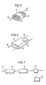
- 1 is a thin layer of the hydroxyapatite or the composites thereof; 2 are electrodes provided at the both ends of the thin layer 1 for measuring its electrical resistance (impedance); 3 are wire leads to connect the electrodes 2 to an apparatus 16 (not shown in Figs. 1, 2, 3 and 4) for measuring electrical resistance (impedance); and 4 and 41 are a refractory substrate or base to support the thin layer 1.
- Fig. 3, 5 is a heater provided on the refractory substrate or base 4 and having provided thereon the thin layer 1.
- Figs. 5 and 6 11 and 12 are a porous hydroxyapatite or composites thereof; 21 and 22 are electrodes; and 31 and 32 are wire leads.
- the electrodes 22 and 22 function as a heater and, at the same time, as an electrode.
- the hydroxy- apatite changes to a carbonate apatite with a significant change in its electrical resistance, which can be utilized for the detection of the presence of carbon dioxide.
- the sensitivity for detecting the carbon dioxide gas can be increased by an increase in temperature at which it is brought into contact with the gas. Accordingly, since the thin layer 1 is used by heating or in a heating atmosphere, it is installed on the refractory substrate or base 4.
- the thin layer 1 has a thickness not greater than 300 pm (most preferably not greater than 200 um) and is in a porous state.
- the wire leads may function as a support, as well. In this case, it is necessary that the wire leads have a sufficient strength and durability.
- the element according to the invention is used at an elevated temperature and, hence, the wire leads, as well as the substrate or base, to be used therein are preferably made of a material which can withstand a high temperature at which the detection is to be effected.
- Fig. 7 shows an example of a preferable flow chart illustrating a case where a gas to be examined is heated.
- 13 is a dehumidifier
- 14 is a heater for a gas to be examined
- 15 is a sensor for detecting the presence of carbon dioxide in which a detection element, which may be any of the types shown by Figs. 1,3,4,5 and 6, is housed
- 16 is an apparatus for measuring electrical resistance (impedance) which is connected to the wire leads 3, 31, and 32
- 17 is a line through which the gas flows.
- the gas to be analyzed is passed through the line 17 and is allowed to enter into the dehumidifier 13, in which the moisture contained in the gas is removed. Thereafter, it is introduced into the heater 14 and then into the sensor 15 for the detection of the presence of carbon dioxide. If carbon dioxide is present in the gas, the measuring apparatus 16 will record a significant increase in the electrical resistance of the detection element, indicating the presence of carbon dioxide. In the case where the gas is heated to a sufficiently high temperature by the heater 14, the relative humidity of the gas could be reduced to an extremely low level even when a substantial amount of moisture is contained therein. In such a case, the influence of the moisture can be limited to a virtually negligible level and, therefore, the dehumifier 13 may not be required.
- Fig. 3 shows an example of a carbon dioxide detection element provided with the thin layer 1 which is to be heated upon measurement.
- the heater 5 is provided in the refractory substrate or base 4, and the thin layer 1 provided with the electrodes 2 at the both ends thereof is formed on the heater 5.
- the thin layer 1 is heated by the heater 5 and is brought into contact with a gas to be examined. If the gas contains carbon dioxide, the electrical resistance of the thin layer 1 increases significantly to indicate the presence of carbon dioxide in the gas examined.
- Fig. 4 shows an example in which a heat-resistant electrical insulator 6 is provided between the thin layer 1 and the heater 5 which is provided on the heat-resistant substrate or base 41.
- the heater 14 shown in Fig. 7 need not be used.
- the electrical resistance increases with the increase in the concentration of carbon dioxide contained in the gas, irrespective of the type of the element used therefor. It is therefore possible to measure the concentration of the carbon dioxide.
- the hydroxyapatite used therefor is represented by the following formula (I): wherein M is an element selected from the group consisting of Ca, Ba, Sr, Pb and Cd; and Z is an element selected from the group consisting of P, As and V, and is incorporated with a compound (a minor component) represented by the formula (I), wherein M is an element selected from the group consisting of Sc, Y, TI, Bi, V, Ni, Mn, Fe, Sn, Rb, Na, K and Cs; and Z is an element selected from the group consisting of Si, Ge, Cr, Mn, AI and B.
- a simpler electrical circuit can be applied to the detection element, irrespective of the type of the element used.
- the thus obtained sintered material was cut into sections with a size of 15 mm (in length) by 10 mm (in width) and then polished.
- a ruthenium oxide paste was coated on the cut piece to form an electrode, and a platinum wire lead was bonded thereto.
- the paste was allowed to dry in a drier at a temperature of from 90 to 100°C. Thereafter, the wired piece was baked in air at a temperature of 850°C for a period of 15 minutes to give a carbon dioxide gas detection element provided with electrodes as shown in Fig. 5.
- Aqueous sodium carbonate solutions having different sodium carbonate concentrations were prepared.
- Carbon dioxide detection elements prepared as in 1-1) above were immersed in one of the sodium carbonate solutions and treated in the same manner as above to a give carbon dioxide gas detection elements incorporated with different amounts of sodium carbonate.
- Aqueous calcium carbonate solutions containing different amounts of calcium carbonate were prepared in the same manner as above.
- the carbon dioxide detection element prepared in 1-1) above was immersed in each of the calcium carbonate solutions and treated in the same manner as above to give a carbon dioxide gas detection element incorporated with a different amount of calcium carbonate.
- the sample incorporated with sodium carbonate prepared in 1-2) above was placed in the electric furnace, in place of the reference sample, and its electrical resistance (R) was measured under the same conditions as in (i) above. The ratio of the electrical resistance (R/Ro) was calculated.
- the ratio R/Ro was measured for each of the samples incorporated with calcium carbonate prepared in 1-3) above, in the same manner as in (ii) above.
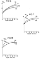
- a reference sample was placed in an electric furnance maintained at 500°C, and its electrical resistance (Ro) in air was measured. Thereafter, the air in the electric furnace was replaced with a pure carbon dioxide gas heated to the same temperature. The change in the electrical resistance of the sample was measured for the period of time shown in Figs. 8 and 9, and the ratio R/Ro was calculated.
- the ordinate indicates the ratio (R/Ro) of the electrical resistance (R) of the sample incorporated with sodium carbonate to that (Ro) of the reference sample; and the abscissa indicates the amount of sodium carbonate used in the immersing treatment in the preparation (indicated as grams of sodium carbonate contained in 100 ml of water used for the treatment).
- the ordinate indicates the ratio (R/Ro) of the electrical resistance (R) of the sample incorporated with calcium carbonate to that (Ro) of the reference sample; and the abscissa indicates the amount of calcium carbonate used in the immersing treatment in the preparation (indicated as grams of calcium carbonate used therefor).
- the ordinate indicates the ratio (R/Ro) of the electrical resistance (R) in carbon dioxide gas to that (Ro) in air; and the abscissa indicates the time (in minutes) elapsed between the measurement and the time when the air in the furnace was replaced with a pure carbon dioxide gas.
- the continuous curves 101 and 111 show the results with the reference sample; the dotted curves 102 and 112 show the results with the sample incorporated with sodium carbonate; and the chained curves 103 and 113 show the results with the sample incorporated with calcium carbonate.
- a carbon dioxide gas detection element (Ca-2) was prepared in the same manner as above, except that a solution containing 0.02 mol/I of calcium chloride was used instead of the solution containing 0.2 mol/I of calcium chloride.
- a carbon dioxide gas detection element (Ca-3) was prepared in the same manner as above, except that a solution containing 0.002 mol/I of calcium chloride was used instead of the solution containing 0.2 mol/I of calcium chloride.
- the reference carbon dioxide detection element prepared in 1-1) above was placed in an electric furnace maintained at 400°C by a temperature controller and filled with air, and the electrical resistance (Ro) of the reference element in air was measured. Thereafter, the air in the electric furnace was replaced with air containing 0.1 %, 1.0% or 10% of carbon dioxide, and the electrical resistance (R) of the reference element was measured in each of the gases.
- the ratio R/Ro i.e., [electrical resistance of the reference element measured in air containing carbon dioxide gas]/ [electrical resistance of the reference element measured in air], was calculated for each case.
- the carbon dioxide detection element (Ca-1) was placed in an electric furnace maintained at 400°C by a temperature controller and filled with air, and the electrical resistance (Ro) of the element in air was measured. Thereafter, the air in the electric furnace was replaced with air containing 1% of carbon dioxide, the electrical resistance (R) of the element was measured, and the ratio R/Ro was calculated therefrom.
- the carbon dioxide gas detection elements (Ca-2) and (Ca-3) were subjected to the same measurement as above to measure their electrical resistances Ro and R, and the ratio R/Ro was calculated therefrom.
- the ordinate indicates the ratio R/Ro, i.e., [electrical resistance of the reference sample measured in air containing carbon dioxide gas]/ [electrical resistance of the reference sample measured in air]; and the abscissa indicates the period of time elapsed after the replacement of the air in the electric furnace with air containing carbon dioxide.
- the continuous curve 201 shows the results obtained in the air containing 0.1% of carbon dioxide; the dotted curve 202 the results in the air containing 1% of carbon dioxide; and the chained curve 203 the results in the air containing 10% of carbon dioxide.
- the ordinate indicates the ratio R/Ro, i.e., (electrical resistance of the sample incorpo-. rated with calcium chloride measured in air containing carbon dioxide]/[electrical resistance of the sample incorporated with calcium chloride measured in air]; and the abscissa indicates the period of time elapsed after the replacement of the air in the electric furnace with air containing carbon dioxide.
- the continuous curve 301 shows the results obtained by the carbon dioxide detection element (Ca-3); the dotted curve 302 the results by the carbon dioxide detection element (Ca-2); and the chained curve 303 the results by the carbon dioxide detection element (Ca-1).
- Ruthenium oxide electrodes were formed by means of a screeen printing on the same alumina substrate as in Example 2 having a size of 2.5 cm x 2.5 cm, and a platinum paste was coated on the electrodes.
- a piece of the hydroxyapatite sheet prepared in 1-1) in Example 2 was placed on the electrodes and treated in the same manner as in 1-1) in Example 2 to give a thin plate sample. Wire leads were attached to the electrodes of the thin plate sample to give a carbon dioxide gas detection element incorporated with platinum.
- Example 2 The thus prepared element was immersed in a solution containing 0.2 mol/I of calcium chloride in the same manner as in 1-2) in Example 2 to give a carbon dioxide gas detection element (Ca-Pt-1).
- Carbon dioxide gas detection elements (Ca-Pt-2) and (Ca-Pt-3) were prepared in the same manner as above, except that a solutions containing 0.02 mol/I and 0.002 mol/I of calcium chloride was used, respectively, instead of the solution containing 0.2 mol/I of calcium chloride.
- the electrical resistances Ro and R of the carbon dioxide gas detection elements (Ca-Pt-1), (Ca-Pt-2) and (Ca-Pt-3) were measured in the same manner as in 2-2) in Example 2, and the ratio R/Ro of the electrical resistance was calculated therefrom.
- the ordinate indicates the ratio R/Ro, i.e., [electrical resistance of the sample incorporated with calcium chloride and platinum measured in the air containing carbon dioxide gas]/[electrical resistance of the sample incorporated with calcium chloride and platinum measured in air]; and the abscissa indicates the period of time elapsed afterthe replacement of the air in the electric furnace with the air containing 1.0% of carbon dioxide.
- the continuous curve 401 shows the results obtained by the carbon dioxide gas detection element (Ca-Pt-3); the dotted curve 402 the results by the element (Ca-Pt-2); and the chained curve 403 the results by the element (Ca-Pt-1).
- a carbon dioxide gas detection element (Ca-Pd-Pt-2) was prepared in the same manner as above, except that a solution containing 0.2 mol/I of calcium chloride and 5 x 10⁻⁴ mol/I of palladium chloride was used instead of the solution containing 0.2 mol/I of calcium chloride and 5 x 10- 3 mol/I of palladium chloride.
- a carbon dioxide gas detection element (Ca-Pd-Pt-3) was prepared in the same manner as above, except that a solution containing 0.2 mol/I of calcium chloride and 5 x 10- 5 mol/I of palladium chloride was used instead of the solution containing 0.2 mol/I of calcium chloride and 5 x 10- 3 mol/I of palladium chloride.
- the electrical resistances Ro and R of the carbon dioxide gas detection elements (Ca-Pd-Pt-1), (Ca-Pd-Pt-2) and (Ca-Pd-Pt-2) were measured in the same manner as in 2-2) in Example 2, and the ratio R/Ro of the electrical resistance was calculated therefrom.
- the ordinate indicates the ratio R/Ro, i.e., [electrical resistance of the sample incorporated with calcium chloride, palladium chloride and platinum measured in air containing carbon dioxide gas]/[electrical resistance of the sample incorporated with calcium chloride, palladium chloride and platinum in air]; and the abscissa indicates the period of time elapsed after the replacement of the air in the electric furnace with the air containing carbon dioxide.
- the continuous curve 501 shows the results obtained by the carbon dioxide gas detection element (Ca-Pd-Pt-3); the dotted curve 502 the results by the element (Ca-Pd-Pt-2); and the chained curve 503 by the element (Ca-Pd-Pt-1).
- a carbon dioxide gas detection element (Ca-Pd-Pt-1) was prepared in the same manner as in (1) in Example 4, using a solution containing 0.2 mol/I of calcium chloride and 5 x 10- 3 mol/I of palladium chloride.
- the carbon dioxide gas detection element (Ca-Pd-Pt-I) was placed in an electric furnace maintained at 400°C by means of a temperature controller, and the electrical resistance (Ro) of the element in air was measured. Thereafter, the air in the electric furnace was replaced with air containing 0.1% of carbon dioxide, and the change in the electrical resistance (R 1 ) of the element was measured with a lapse of time.
- the carbon dioxide gas detection element (Ca-Pd-Pt-1) was placed in an electric furnace maintained at 400°C by means of a temperature controller, and the electrical- resistance (Ro) of the element in air was measured. The element was taken out of the furnace and allowed to cool to room temperature. The element was again placed in the electric furnace, and the air in the furnace was replaced with air containing 0.1 % of carbon dioxide. The change in the electrical resistance (R 2 ) of the element was measured with a lapse of time.
- the ordinate indicates the ratio R i /Ro or R2/Ro, i.e., [electrical resistance of the element measured in air containing carbon dioxide]/[electrical resistance of the element measured in air]; and the abscissa indicates the period of time elapsed after the replacement of the air in the electric furnace with the air containing carbon dioxide gas.
- the continuous curve 601 shows the results obtained with respect to the detection element in which the heating-and-cooling treatment was not carried out; and the dotted curve 602 shows the results obtained with respect to the detection element in which the heating-and-cooling treatment was carried out.
- a carbon dioxide gas detection element (Cd-Pd-Pt-1) was prepared in the same manner as in (1) in Example 4, using a solution containing 0.2 g mol/I of calcium chloride and 5 x 10- 3 mol/I of palladium chloride.
- the carbon dioxide gas detection element (Ca-Pd-Pt-1) was placed in an electric furnace maintained at 400°C by means of a temperature controller, and the electrical resistance (Ro) of the element in air was measured. Thereafter, the air in the electric furnace was replaced with an air containing 0.1% of carbon dioxide, and the change in the electrical resistance (R 3 ) of the element was measured with a lapse of time. The element was taken out of the furnace and allowed to cool to room temperature. The element was again placed in the electric furnace, and the air in the furnace was replaced with air containing 0.1% of carbon dioxide. The change in the electrical resistance (R 4 ) of the element was measured with a lapse of time.
- the ordinate indicates the ratio RjRo or R 4 /Ro, i.e., [electrical resistance of the element measured in air containing carbon dioxide gas]/ [electrical resistance of the element measured in air]; and the abscissa indicates the period of time elapsed after the replacement of the air in the electric furnace with the air containing carbon dioxide gas.
- the continuous curve 701 shows the results obtained with respect to the detection element in which the treatment with carbon dioxide gas was not carried out; and the dotted curve 702 shows the results obtained with respect to the detection element in which the treatment with carbon dioxide gas was carried out.
Landscapes
- Chemical & Material Sciences (AREA)
- Health & Medical Sciences (AREA)
- Life Sciences & Earth Sciences (AREA)
- General Health & Medical Sciences (AREA)
- Immunology (AREA)
- Engineering & Computer Science (AREA)
- Analytical Chemistry (AREA)
- Biochemistry (AREA)
- Pathology (AREA)
- General Physics & Mathematics (AREA)
- Physics & Mathematics (AREA)
- Chemical Kinetics & Catalysis (AREA)
- Electrochemistry (AREA)
- Combustion & Propulsion (AREA)
- Food Science & Technology (AREA)
- Medicinal Chemistry (AREA)
- Investigating Or Analyzing Materials By The Use Of Fluid Adsorption Or Reactions (AREA)
Claims (14)
Priority Applications (1)
| Application Number | Priority Date | Filing Date | Title |
|---|---|---|---|
| AT86106730T ATE55834T1 (de) | 1985-05-16 | 1986-05-16 | Element zur erfassung von kohlendioxidgas und verfahren zur herstellung des elements. |
Applications Claiming Priority (4)
| Application Number | Priority Date | Filing Date | Title |
|---|---|---|---|
| JP10266685A JPS61262647A (ja) | 1985-05-16 | 1985-05-16 | 炭酸ガスの検出素子材料およびその製造法 |
| JP102666/85 | 1985-05-16 | ||
| JP85126/86 | 1986-04-15 | ||
| JP8512686A JPS62242847A (ja) | 1986-04-15 | 1986-04-15 | 高感度の炭酸ガスの検出素子材料およびその製造法 |
Publications (3)
| Publication Number | Publication Date |
|---|---|
| EP0201936A2 EP0201936A2 (de) | 1986-11-20 |
| EP0201936A3 EP0201936A3 (en) | 1987-06-16 |
| EP0201936B1 true EP0201936B1 (de) | 1990-08-22 |
Family
ID=26426156
Family Applications (1)
| Application Number | Title | Priority Date | Filing Date |
|---|---|---|---|
| EP86106730A Expired - Lifetime EP0201936B1 (de) | 1985-05-16 | 1986-05-16 | Element zur Erfassung von Kohlendioxidgas und Verfahren zur Herstellung des Elements |
Country Status (5)
| Country | Link |
|---|---|
| US (1) | US4755473A (de) |
| EP (1) | EP0201936B1 (de) |
| AU (1) | AU583621B2 (de) |
| CA (1) | CA1256358A (de) |
| DE (1) | DE3673556D1 (de) |
Families Citing this family (12)
| Publication number | Priority date | Publication date | Assignee | Title |
|---|---|---|---|---|
| JPH01109250A (ja) * | 1987-10-22 | 1989-04-26 | Toshiba Corp | ガスセンサ |
| US5057436A (en) * | 1989-10-02 | 1991-10-15 | Agmaster, Inc. | Method and apparatus for detecting toxic gases |
| US5215498A (en) * | 1991-03-04 | 1993-06-01 | Gaztech International Corporation | Ventilation controller |
| US5222388A (en) * | 1991-03-19 | 1993-06-29 | University Of California Patent, Trademark & Copyright Office | Nitrogen dioxide detection |
| DE4334410C3 (de) * | 1993-10-08 | 2002-05-29 | Fraunhofer Ges Forschung | Dünnschicht-Gassensor |
| US5993624A (en) * | 1995-12-07 | 1999-11-30 | Matsushita Electric Industrial Co., Ltd. | Carbon dioxide gas sensor |
| DE19617297A1 (de) * | 1996-04-30 | 1997-11-13 | Brand Gerhart Rosemarie | Simultane Detektion von oxidierbaren und reduzierbaren Gasen mit Metalloxidsensoren unter Einsatz von Impedanzspektroskopie |
| CA2527498C (en) * | 2002-06-10 | 2015-12-29 | Trustees Of Tufts College | Total organic carbon (toc) analyzer |
| US20070183929A1 (en) * | 2006-02-09 | 2007-08-09 | OI Analytical | Total organic carbon analysis |
| DE102009054435A1 (de) * | 2009-11-25 | 2011-05-26 | Kechter, Andreas, Dipl.-Ing. | Heizbarer Gassensor und Verfahren zu dessen Herstellung |
| US9170193B2 (en) | 2013-06-06 | 2015-10-27 | General Electric Company | Detecting coolant leaks in turbine generators |
| US9097657B2 (en) | 2013-07-23 | 2015-08-04 | General Electric Company | Leak detection of stator liquid cooling system |
Family Cites Families (6)
| Publication number | Priority date | Publication date | Assignee | Title |
|---|---|---|---|---|
| NL278407A (de) * | 1961-05-15 | |||
| US4157378A (en) * | 1973-01-11 | 1979-06-05 | Colgate Palmolive Company | Process for preparing fluorapatite |
| JPS6050743B2 (ja) * | 1976-06-02 | 1985-11-09 | 旭光学工業株式会社 | アパタイト焼結体及びその製造方法 |
| LU76937A1 (de) * | 1977-03-11 | 1978-10-18 | ||
| JPS602761B2 (ja) * | 1979-08-10 | 1985-01-23 | 三菱電機株式会社 | 感湿素子 |
| US4419889A (en) * | 1981-03-27 | 1983-12-13 | Mitsubishi Denki Kabushiki Kaisha | Moisture sensitive device |
-
1986
- 1986-05-16 CA CA000509323A patent/CA1256358A/en not_active Expired
- 1986-05-16 AU AU57509/86A patent/AU583621B2/en not_active Ceased
- 1986-05-16 DE DE8686106730T patent/DE3673556D1/de not_active Expired - Lifetime
- 1986-05-16 US US06/863,891 patent/US4755473A/en not_active Expired - Fee Related
- 1986-05-16 EP EP86106730A patent/EP0201936B1/de not_active Expired - Lifetime
Also Published As
| Publication number | Publication date |
|---|---|
| US4755473A (en) | 1988-07-05 |
| AU583621B2 (en) | 1989-05-04 |
| EP0201936A2 (de) | 1986-11-20 |
| CA1256358A (en) | 1989-06-27 |
| AU5750986A (en) | 1986-11-20 |
| EP0201936A3 (en) | 1987-06-16 |
| DE3673556D1 (de) | 1990-09-27 |
Similar Documents
| Publication | Publication Date | Title |
|---|---|---|
| EP0201936B1 (de) | Element zur Erfassung von Kohlendioxidgas und Verfahren zur Herstellung des Elements | |
| US9164080B2 (en) | System and method for sensing NO | |
| JP2001318069A (ja) | 呼気ガス分析装置 | |
| US4723439A (en) | Humidity detector | |
| WO2008047115A1 (en) | Gas sensor | |
| JP2789522B2 (ja) | 基板上に黄緑石型酸化タングステン層を形成する方法および該黄緑石型酸化タングステン層含有湿度センサ素子 | |
| JPS60228949A (ja) | 被検混合ガス中の還元ガスを検知する方法及びそのための装置 | |
| WO2008009951A1 (en) | Electrochemical gas sensor comprising mesoporous layer between working and counter electrodes | |
| US4280115A (en) | Humidity sensor | |
| AU688069B2 (en) | Ion selective ceramic membrane | |
| Torvela et al. | Dual response of tin dioxide gas sensors characteristic of gaseous carbon tetrachloride | |
| JPH0418260B2 (de) | ||
| JPH0580021A (ja) | 炭酸ガス検知センサ | |
| JPH0570785B2 (de) | ||
| JPH11174023A (ja) | 固体電解質型炭酸ガスセンサ素子 | |
| JPH01290552A (ja) | 炭酸ガスの検出素子材料およびその製造法 | |
| JPH06186193A (ja) | 炭酸ガスセンサ素子および炭酸ガス濃度測定方法 | |
| RU2119695C1 (ru) | Полупроводниковый материал для адсорбционных сенсоров низкомолекулярных органических соединений и способ его изготовления | |
| Nagai et al. | Fabrication and evaluation of porous β/β ″ Al2O3 ceramics prepared by the sol-gel process | |
| SU1133537A1 (ru) | Гигрометрический датчик | |
| JPS61262647A (ja) | 炭酸ガスの検出素子材料およびその製造法 | |
| JPH0413957A (ja) | 炭酸ガス検知素子およびそれを用いる炭酸ガスの検知方法 | |
| KR100210572B1 (ko) | 활성이온의 측정방법 및 측정장치 | |
| AU586836B2 (en) | Sensors and method for the measurement of oxygen partial pressures in hot gases | |
| JP2001141693A (ja) | 固体電解質型窒素酸化物ガスセンサ素子 |
Legal Events
| Date | Code | Title | Description |
|---|---|---|---|
| PUAI | Public reference made under article 153(3) epc to a published international application that has entered the european phase |
Free format text: ORIGINAL CODE: 0009012 |
|
| AK | Designated contracting states |
Kind code of ref document: A2 Designated state(s): AT BE CH DE FR GB IT LI NL SE |
|
| PUAL | Search report despatched |
Free format text: ORIGINAL CODE: 0009013 |
|
| AK | Designated contracting states |
Kind code of ref document: A3 Designated state(s): AT BE CH DE FR GB IT LI NL SE |
|
| 17P | Request for examination filed |
Effective date: 19870602 |
|
| 17Q | First examination report despatched |
Effective date: 19890201 |
|
| GRAA | (expected) grant |
Free format text: ORIGINAL CODE: 0009210 |
|
| AK | Designated contracting states |
Kind code of ref document: B1 Designated state(s): AT BE CH DE FR GB IT LI NL SE |
|
| PG25 | Lapsed in a contracting state [announced via postgrant information from national office to epo] |
Ref country code: SE Free format text: THE PATENT HAS BEEN ANNULLED BY A DECISION OF A NATIONAL AUTHORITY Effective date: 19900822 Ref country code: NL Effective date: 19900822 Ref country code: IT Free format text: LAPSE BECAUSE OF FAILURE TO SUBMIT A TRANSLATION OF THE DESCRIPTION OR TO PAY THE FEE WITHIN THE PRE;WARNING: LAPSES OF ITALIAN PATENTS WITH EFFECTIVE DATE BEFORE 2007 MAY HAVE OCCURRED AT ANY TIME BEFORE 2007. THE CORRECT EFFECTIVE DATE MAY BE DIFFERENT FROM THE ONE RECORDED.SCRIBED TIME-LIMIT Effective date: 19900822 Ref country code: AT Effective date: 19900822 |
|
| REF | Corresponds to: |
Ref document number: 55834 Country of ref document: AT Date of ref document: 19900915 Kind code of ref document: T |
|
| REF | Corresponds to: |
Ref document number: 3673556 Country of ref document: DE Date of ref document: 19900927 |
|
| ET | Fr: translation filed | ||
| NLV1 | Nl: lapsed or annulled due to failure to fulfill the requirements of art. 29p and 29m of the patents act | ||
| PLBE | No opposition filed within time limit |
Free format text: ORIGINAL CODE: 0009261 |
|
| STAA | Information on the status of an ep patent application or granted ep patent |
Free format text: STATUS: NO OPPOSITION FILED WITHIN TIME LIMIT |
|
| 26N | No opposition filed | ||
| PGFP | Annual fee paid to national office [announced via postgrant information from national office to epo] |
Ref country code: CH Payment date: 19940516 Year of fee payment: 9 |
|
| PGFP | Annual fee paid to national office [announced via postgrant information from national office to epo] |
Ref country code: BE Payment date: 19940711 Year of fee payment: 9 |
|
| PGFP | Annual fee paid to national office [announced via postgrant information from national office to epo] |
Ref country code: GB Payment date: 19950505 Year of fee payment: 10 |
|
| PGFP | Annual fee paid to national office [announced via postgrant information from national office to epo] |
Ref country code: FR Payment date: 19950510 Year of fee payment: 10 |
|
| PGFP | Annual fee paid to national office [announced via postgrant information from national office to epo] |
Ref country code: DE Payment date: 19950511 Year of fee payment: 10 |
|
| PG25 | Lapsed in a contracting state [announced via postgrant information from national office to epo] |
Ref country code: LI Effective date: 19950531 Ref country code: BE Effective date: 19950531 Ref country code: CH Effective date: 19950531 |
|
| BERE | Be: lapsed |
Owner name: SEKISUI KASEIHIN KOGYO K.K. Effective date: 19950531 |
|
| REG | Reference to a national code |
Ref country code: CH Ref legal event code: PL |
|
| PG25 | Lapsed in a contracting state [announced via postgrant information from national office to epo] |
Ref country code: GB Effective date: 19960516 |
|
| GBPC | Gb: european patent ceased through non-payment of renewal fee |
Effective date: 19960516 |
|
| PG25 | Lapsed in a contracting state [announced via postgrant information from national office to epo] |
Ref country code: FR Effective date: 19970131 |
|
| PG25 | Lapsed in a contracting state [announced via postgrant information from national office to epo] |
Ref country code: DE Effective date: 19970201 |
|
| REG | Reference to a national code |
Ref country code: FR Ref legal event code: ST |