EP0201939B1 - Amortisseur de vibrations de torsion à amortissement variable - Google Patents
Amortisseur de vibrations de torsion à amortissement variable Download PDFInfo
- Publication number
- EP0201939B1 EP0201939B1 EP86106788A EP86106788A EP0201939B1 EP 0201939 B1 EP0201939 B1 EP 0201939B1 EP 86106788 A EP86106788 A EP 86106788A EP 86106788 A EP86106788 A EP 86106788A EP 0201939 B1 EP0201939 B1 EP 0201939B1
- Authority
- EP
- European Patent Office
- Prior art keywords
- assembly
- clutch
- damping
- driveline
- viscous
- Prior art date
- Legal status (The legal status is an assumption and is not a legal conclusion. Google has not performed a legal analysis and makes no representation as to the accuracy of the status listed.)
- Expired
Links
Images


Classifications
-
- F—MECHANICAL ENGINEERING; LIGHTING; HEATING; WEAPONS; BLASTING
- F16—ENGINEERING ELEMENTS AND UNITS; GENERAL MEASURES FOR PRODUCING AND MAINTAINING EFFECTIVE FUNCTIONING OF MACHINES OR INSTALLATIONS; THERMAL INSULATION IN GENERAL
- F16D—COUPLINGS FOR TRANSMITTING ROTATION; CLUTCHES; BRAKES
- F16D47/00—Systems of clutches, or clutches and couplings, comprising devices of types grouped under at least two of the following sets of groups: F16D1/00 - F16D9/00, F16D11/00 - F16D23/00, F16D25/00 - F16D29/00, F16D31/00 - F16D39/00, F16D41/00 - F16D45/00
-
- F—MECHANICAL ENGINEERING; LIGHTING; HEATING; WEAPONS; BLASTING
- F16—ENGINEERING ELEMENTS AND UNITS; GENERAL MEASURES FOR PRODUCING AND MAINTAINING EFFECTIVE FUNCTIONING OF MACHINES OR INSTALLATIONS; THERMAL INSULATION IN GENERAL
- F16D—COUPLINGS FOR TRANSMITTING ROTATION; CLUTCHES; BRAKES
- F16D13/00—Friction clutches
- F16D13/12—Friction clutches with an expansible band or coil co-operating with the inner surface of a drum or the like
-
- F—MECHANICAL ENGINEERING; LIGHTING; HEATING; WEAPONS; BLASTING
- F16—ENGINEERING ELEMENTS AND UNITS; GENERAL MEASURES FOR PRODUCING AND MAINTAINING EFFECTIVE FUNCTIONING OF MACHINES OR INSTALLATIONS; THERMAL INSULATION IN GENERAL
- F16F—SPRINGS; SHOCK-ABSORBERS; MEANS FOR DAMPING VIBRATION
- F16F15/00—Suppression of vibrations in systems; Means or arrangements for avoiding or reducing out-of-balance forces, e.g. due to motion
- F16F15/10—Suppression of vibrations in rotating systems by making use of members moving with the system
- F16F15/12—Suppression of vibrations in rotating systems by making use of members moving with the system using elastic members or friction-damping members, e.g. between a rotating shaft and a gyratory mass mounted thereon
- F16F15/121—Suppression of vibrations in rotating systems by making use of members moving with the system using elastic members or friction-damping members, e.g. between a rotating shaft and a gyratory mass mounted thereon using springs as elastic members, e.g. metallic springs
- F16F15/1213—Spiral springs, e.g. lying in one plane, around axis of rotation
-
- F—MECHANICAL ENGINEERING; LIGHTING; HEATING; WEAPONS; BLASTING
- F16—ENGINEERING ELEMENTS AND UNITS; GENERAL MEASURES FOR PRODUCING AND MAINTAINING EFFECTIVE FUNCTIONING OF MACHINES OR INSTALLATIONS; THERMAL INSULATION IN GENERAL
- F16H—GEARING
- F16H45/00—Combinations of fluid gearings for conveying rotary motion with couplings or clutches
- F16H45/02—Combinations of fluid gearings for conveying rotary motion with couplings or clutches with mechanical clutches for bridging a fluid gearing of the hydrokinetic type
-
- F—MECHANICAL ENGINEERING; LIGHTING; HEATING; WEAPONS; BLASTING
- F02—COMBUSTION ENGINES; HOT-GAS OR COMBUSTION-PRODUCT ENGINE PLANTS
- F02B—INTERNAL-COMBUSTION PISTON ENGINES; COMBUSTION ENGINES IN GENERAL
- F02B1/00—Engines characterised by fuel-air mixture compression
- F02B1/02—Engines characterised by fuel-air mixture compression with positive ignition
- F02B1/04—Engines characterised by fuel-air mixture compression with positive ignition with fuel-air mixture admission into cylinder
Definitions
- This invention relates to driveline torsion damping mechanisms operable over the entire operational range of a driveline. More specifically, the invention relates to such mechanisms for vehicle drivelines.
- the speed of an Otto or Diesel engine output or crankshaft varies even during so-called steady-state operation of the engine, i.e., the shaft continuously accelerates and decelerates about the average speed of the shaft.
- the accelerations and decelerations are, of course for the most part, a result of power pulses from the engine cylinders.
- the pulses may be of uniform frequency and amplitude when cylinder charge density, air/fuel ratio, and ignition are uniform. However, such uniformity does not always occur, thereby producing pulses which vary substantially in frequency and amplitude.
- the pulses which are herein referred to torsionals, are transmitted through vehicle drivelines and to passengers in vehicles.
- torsionals which manifest themselves as vibrations, are detrimental to drivelines and derogate passenger-ride quality. Further, when an engine is abruptly accelerated and/or decelerated by accelerator pedal movement, torque pulses ring through the driveline and also derogate ride quality, such pulses are herein also referred to as torsionals.
- torsion damping devices or schemes have been proposed and used to isolate and dampen driveline torsionals.
- master clutches used in combination with mechanical transmissions, have long employed springs and secondary mechanical friction devices to respectively isolate and dampen torsionals.
- torsionals are isolated or absorbed by a plurality of circumferentially spaced, coil springs disposed in parallel between the master clutch primary friction input and splined output. Damping is provided by secondary mechanical friction surfaces disposed in parallel with the springs and biased together with a predetermined force. Damping occurs when the amplitude of the torsionals exceeds the breakaway or slip torque of the secondary friction surfaces.
- portions of the torsionals less than the slip torque of the secondary friction surfaces are transmitted directly through the clutch without flexing or isolation by the springs, i.e., the arrangement provides neither torsion isolation nor damping. If the slip torque of the secondary friction surfaces is reduced by design or wear of the secondary surfaces, damping is reduced. Further, any portions of the torsionals greater than the spring energy absorption or storage capacity are also transmitted directly through the clutch. If the spring rate is increased to provide greater storage capacity and prevent spring collapse, the springs transmit lesser amplitude torsionals directly through with little or no effective isolation or absorption of the torsionals.
- torque converters have many advantages, one being torsional damping, they embody inherent slip and, therefore, inherent losses in vehicle fuel economy.
- various efforts have been made to bypass the torque converter with some manner of direct drive which is typically brought into play when a vehicle is operating in the higher speed ratios of the transmission. While these direct-drive bypass arrangements have resulted in fuel economy improvement, they have also brought back driveline vibration with resultant derogation in the vehicle ride quality that passengers have become accustomed to over the years.
- the direct drive bypasses have been in the form of master type friction clutches with torsion damping devices similar to the previously mentioned devices.
- One example of such a bypass is disclosed in U.S. Patent 4 194 604.
- Two further examples of bypass drives are disclosed in U.S. Patents 3 977 502 and 4 317 510.
- the master type clutch engagement force is such that the clutch primary friction surface continuously slips or slips in response to torsionals above a predetermined amount. This arrangement is difficult to control since the engagement force must vary with driveline torque.
- a third bypass arrangement includes the master type clutch in combination with low-rate torsion isolation springs which may be of the helical torsion type or of the torsion bar type analogous to the arrangement disclosed in previously mentioned Patent 1 978 922. It is also known to use flat torsion springs in vibration dampers, as disclosed in U.S. Patent 4 181 208.
- EP-A 154 088 discloses the use of a viscous coupling in lieu of the secondary mechanical friction surfaces used in the prior art torsional damping mechanisms. Since the clutching medium therein is a viscous liquid, breakaway torque associated with the mechanical friction surfaces is eliminated. Hence, the coupling provides damping over the entire operational or torque range of the assembly. The coupling has a constant damping factor and has provided excellent results in tested vehicles.
- the torsion damping mechanism disclosed herein improves the assembly of the EP-A 154 088 by varying the damping factor of the viscous coupling therein.
- Another object of the present invention is to provide such a mechanism which varies the damping factor of the mechanism as a function of driveline torque.
- the torsion damping mechanism of the present invention is defined in Claim 1, and is adapted for installation in a driveline, featuring an input drive and an output drive respectively driven by an engine and driving a load.
- the torsion damping mechanism is disposed between the drives and includes a torsional energy isolating spring(s) and a torsional energy damping device disposed in parallel with the spring; the spring is connected at its opposite ends to the drives and allows limited relative rotation between the drives.
- the torsion damping mechanism includes first and second members mounted for relative rotation about a common axis for clutching coaction therebetween to damp driveline torsionals, and spring(s) interconnecting the members in parallel with the clutching coaction for transmitting steady-state driveline between the input and output drives and for isolating driveline torsionals.
- the improvement comprises clutching surfaces defined by the members and retained against axial and radial movement relative to each other; the surfaces are operative to effect the clutching coaction between the members, and the surfaces are shaped to vary the amount of clutching coaction for varying the amount of damping of the driveline torsionals in response to the level of steady-state driveline torque being transmitted by the spring(s).
- the first member forms part of an annular housing assembly defining an annular chamber containing a viscous shear liquid
- the second member forms part of an annular clutch assembly disposed within the chamber
- the surfaces are operative to vary the amount of viscous clutching coaction and accordingly the amount of damping of the driveline torsionals in response to relative rotational positions of the surfaces.
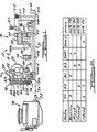
- the motor vehicle driveline seen schematically in FIGURE 1, includes an internal combustion engine 10 and an automatic transmission 12 having an output drive or gear 14 for driving a load, such as unshown rear and/or front wheels of a vehicle.
- the transmission 12 comprises a hydrokinetic fluid coupling or torque converter 16, a ratio section 18, and a torsion damping mechanism 19 including a spring assembly 20 and a viscous coupling assembly 22.
- Components 16-22 are substantially symmetrical about a rotational axis defined by a shaft 21 of the transmission and are shown only above the axis for simplicity and brevity.
- Torque converter 16 is disposed within a torque converter housing 24 rotationally driven by an input drive 26 connected directly to an output or crankshaft 28 of the engine.
- Converter 16 may be of any well-known type and includes an impeller 30 driven by housing 24, a turbine 32 driven hydroki- netically by the impeller, and a stator 34 connectable by a one-way roller clutch 36 to a ground such as a nonrotatable portion of the unshown transmission housing.
- Transmission 12 is a modified form of the general known class of split input torque transmissions disclosed in U.S. Patent 4,398, 436 and British Patent Application 2,099,091A, both of which are incorporated herein by reference.
- Ratio section 18 comprises a planetary gear set 38 controlled by friction clutches C-1, C-2, one -way clutch OWC-1 and brakes B-1, B-2 to provide a reverse and three forward speed ratio modes of operation.
- Planetary gear set 38 includes a first sun gear 40, first and second sets of planetary gears 42, 44 supported by a common planet carrier 46, a ring gear 48, and a second sun gear 50.
- Sun gear 40 is connectable to a first quill or torque converter driven shaft 52 via clutch C-1 or clutch OWG1.
- the first and second sets of planetary gears are in constant mesh with each other, with sun gear 40, and with ring gear 48, respectively.
- Planet carrier 46 is in constant or direct driving relation with output gear 14.
- Ring gear 48 is connectable to ground via brake B-1 or to a second quill shaft 54 via clutch C-2.
- Shafts 21, 54 are fixedly interconnected at 56, and shaft 54 is connected to clutch C-2 via a radially extending flange 58.
- Sun gear 50 is in constant mesh with planetary gears 42 and is connectable to ground via brake B-2.
- Ratio section 18 further includes an oil pump 60 driven by shaft 21.
- spring assembly 20 includes two flat torsion springs 61, 62, more clearly seen in FIGURE 4;
- the viscous coupling assembly 22 includes an annular housing assembly 64 and an annular clutch assembly 66.
- Housing assembly 64 includes an annular radially extending sidewall member 24a defined by the left wall of torque converter housing 24 and an annular radially extending wall member 68 fixed at its radially outer periphery to housing 24. Walls 24a, 68 define an annular chamber 70 containing a viscous liquid.
- Annular clutch assembly 66 includes an annular clutch member 72 disposed for limited rotation in the chamber relative to the housing and fixed to a hub assembly 74.
- the hub assembly is, in turn, fixed to transmission shafts 21, 54, at 56 and to the inner race of a one-way clutch OWC-2 having its outer race fixed to turbine 32.
- Springs 61, 62 are fixed at their radially outer ends 61a, 62a to housing 24 and at their radially inner ends 61 b, 62b to hub assembly 74 in FIGURE 1.
- Hub assembly 74 is clutchable to turbine 32 and quill shaft 52 via one-way clutch OWC-2.
- Clutches OWC-1 and OWC-2 are preferably of the roller type. Only spring ends 61 a and 62b are visable in FIGURE 1.
- Springs 61, 62 resiliently connect torque converter housing 24 directly to transmission shafts 21, 54.
- the springs also resiliently interconnect coupling assemblies 64, 66 for allowing relative rotational positioning of the assemblies in response to variations in the steady-state driveline torque being transmitted by the springs, and for allowing relative to-and-fro rotation of the assemblies about the steady-state positions of the assemblies in response to driveline torsionals and in response to abrupt changes in driveline torque.
- transmission 12 Operation of transmission 12 is in accordance with the figure 2 chart, showing clutch and brake engagements to effect the reverse and forward speed ratio modes of operation.
- 100% of driveline torque is transmitted to the ratio section via the torque converter (T/C).
- 100% of the driveline torque is transmitted via torsion spring assembly (T/S) 20.
- clutch OWC-2 engages to provide a torque reaction for sun gear 40.
- driveline torsionals emanating from the engine are isolated by torsion spring assembly 20 between members 24a, 68, 72 of the viscous coupling.
- the damping occurs independent of the steady-state torque in the driveline and independent of the magnitude of the torsionals, since the viscous clutching coaction between members 24a, 68, 72 of the viscous coupling is always proportional to the magnitude of the torsionals. That is, since the members are viscously interconnected, the members will always slip and dampen pulses or torsionals capable of deflecting the torsion springs of spring assembly 20.
- torsion damping mechanism 19 is substantially the same as the torsion damping mechanism disclosed in the previously mentioned EP-A 154 088.
- This viscous coupling provides a constant damping factor (viscous clutching coaction) and provides excellent results over the entire driveline torque range of tested vehicles. These results may be further improved by varying the damping factor of the viscous coupling.
- Figures 3-6 herein illustrate a viscous coupling having a variable damping factor as a function of driveline torque.
- Mechanism 19 of this application may employ a torsion shaft or helical coil springs such as disclosed in EP-A 0 154 088 in lieu of the flat torsion springs disclosed herein.
- viscous coupling 22 herein may employ concentric interdigitally arranged rings defining viscous clutching surfaces such as disclosed in the copending application in lieu of the flat viscous clutching surfaces disclosed herein.
- this embodiment includes means providing the viscous coupling with the variable damping factor feature.
- the coupling is otherwise substantially the same as schematically illustrated in figure 1.
- coupling 22 includes several other advantageous features: 1) the left sidewall 24a of the coupling housing assembly 64 is defined by the torque converter housing, thereby (a) negating the cost of one sidewall, (b) reducing the thickness of the coupling which, at best, is difficult to fit into the available space within the torque converter housing, and (c) negating the need for a second dynamic seal to prevent fluid leakage into and out of the coupling; 2) the flat plate structure of the viscous clutching surfaces further reduces the coupling thickness and additionally reduces the coupling cost since the housing and clutching members 24a, 68, 72 may be formed of stampings requiring little or no machining; and 3) the reduced thickness provided by features 1 and 2 provides space in the torque converter housing for spring assembly 20.
- the annular housing assembly 64 is composed of the sidewall members 24a, 68 spaced apart by an annular ring 76 to define chamber 70 and to establish the axial distance between inner surfaces 24b, 68a of the members. Surfaces 24b, 68a are substantially parallel and cooperate with clutch member 72 to define the viscous clutching or working portion of the coupling.
- Ring 76 is secured to housing 24 by an unshown weld and sidewall member 68 is secured to ring 76 by a plurality of circumferentially spaced screws 78.
- the outer periphery of chamber 70 is sealed by the weld and a static seal 80.
- the radially outer portion of sidewall member 68 includes a cylindrical flange 68b having spring ends 61 a and 62a secured thereto by screws 82, as may be seen in FIGURE 4.
- the radially inner portion of member 68 includes a cylindrical flange 68c extending axially to the left and defining a bearing surface on its inner surface.
- Hub assembly 74 of clutch assembly 66 includes a hub member 84 and an annular radially extending flange member 86 secured to the inner race of clutch OWC-2 by a plurality of circumferentially spaced screws 88. Two radially extending slots in the radially outer portion of flange 86 receive tangs or ends 61 b, 62b of springs 61, 62, as fully shown in FIGURE 4.
- Hub member 84 includes a radially inner hub portion 84a, an annular intermediate hub portion 84b, and a cylindrical outer flange 84c.
- Hub portion 84a includes a blind hexagonal opening mating with a hexagonal portion 21 a at the left end of shaft 21.
- the right end of shaft 21 includes a hexagonal portion 21 b received in a mating hexagonal opening in a bracket 60a.
- the bracket drives oil pump 60, shown schematically only in FIGURE 1.
- the inner surface of hub portion 84b includes a portion 84d receiving a smooth outer surface on the left end of quill shaft 54 and a splined portion 84e mating with splines 54a on the outer surface of the quill shaft. Flow of pressurized transmission fluid along the interface of hub portion 84b and quill shaft 54 is prevented by a static seal 90.
- a bearing sleeve 92 pressed on the outer surface of hub portion 84b, provides a journal for the bearing surface defined by cylindrical flange 68c of sidewall member 68.
- Fluid leakage into and out of chamber 70 at the hub is prevented by a single dynamic seal 94 of the double lip elastomer-type pressed at its outer periphery on the inner periphery of cylindrical flange 84c and running on its inner periphery against a sleeve 96 pressed on the outer periphery of cylindrical flange 68c of sidewall member 68.
- a snap ring 98 prevents axial movement of the seal.
- Transmission fluid leakage along the journal surface of bearing 92 is directed to an oil return via one or more radially inwardly extending holes 99.
- Metal-to-metal contact between housing wall 24a and hub member 84 is prevented by an annular thrust bearing 100.
- the outer periphery of hub member 84 or flange portion 84c includes a plurality of circumferentially spaced teeth or splines 84f.
- Clutch member 72 is substantially annular and includes an inner periphery having a plurality of circumferentially spaced splines 72a mating with splines 84f of hub member 84, an intermediate or working portion having oppositely facing surfaces 72b, 72c, and a radially outer portion 72d.
- Outer portion 72d includes a plurality of circumferentially spaced throughholes each receiving from opposite sides a round antifriction material 102 of T-shaped cross section for centering clutch member 72 in chamber 70.
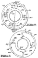
- surface 24b includes arcuate recesses 24c, 24d each of about 100 arc degrees in length and defining therebetween arcuate clutching surfaces 24e, 24f each of about 80 arc degrees in length.
- Clutching surfaces 24e, 24f are fully visible in FIGURE 5 and partly visible in FIGURE 6.
- the leading/trailing edges of recess 24c, 24d are designated 24g, 24h, 24i, 24j. These edges also define the leading/trailing edges of clutching surfaces 24e, 24f.
- Surface 68a of sidewall member 68 includes identical arcuate recesses disposed directly opposite recesses 24c, 24d and arcuate clutching surfaces disposed directly opposite clutch surfaces 24e, 24f.
- the recesses and clutching surfaces of sidewall surface 68a are not shown in FIGURES 5 and 6; one recess designated 68d is visible in FIGURE 3.
- the oppositely facing recesses and arcuate clutching surfaces in sidewall surfaces 24b, 68a provide chamber 70 with axial widths which change stepwise from a maximum to a minimum.
- the recesses are machined into the sidewalls.
- the recesses may be formed in other ways, e.g., the recesses may be made by deforming the sidewalls outward.
- Surfaces 72b, 72c also include arcuate recesses or throughopenings 72f, 72g of about 100 arc degrees in length and defining therebetween, on the oppositely facing surfaces 72b, 72c of the clutch member 72, arcuate clutching surfaces of about 80 arc degrees in length.
- the arcuate clutching surfaces on surface 72b are not shown in the drawing.
- the arcuate clutching surfaces on surface 72c are designated 72h, 72i, and both are fully visible in FIGURES 5 and 6.
- the leading/trailing edges of throughopenings 72f, 72g are designated 72j, 72k, 72m, and 72n. These edges also define the leading/trailing edges of the clutching surfaces on the oppositely facing surfaces 72b, 72c.
- FIGURE 5 depicts recess 24c extending between the 270° and 10 ° positions, recess 24d extending between the 90 ° and 190 ° positions, throughopening 72f extending between the 355° and 95° positions, and throughopening 72g extending between the 175 ° and 275 ° positions.
- FIGURE 6 the rotational position of clutch member 72 is unchanged and housing assembly 64 is rotated 80 arc degrees clockwise. If housing assembly 64 were rotated an additional 5 arc degrees, each of the recess- es/throughopenings would be completely disposed opposite each other and likewise each of the arcuate clutching surfaces would be completely disposed opposite each other.
- the recess/throughopening and arcuate clutching surface arrangement provides viscous coupling 22 with a clutching or damping factor which varies in response to variations in the relative rotational positions of the arcuate clutch surfaces.
- the damping factor of the coupling is a minimum.
- the arcuate clutching surfaces overlie each other, as substantially shown in FIGURE 6, the damping factor of the coupling is a maximum.
- torsion damping mechanism 19 may be assembled such that the arcuate clutching surfaces are as shown in FIGURE 5 when a land vehicle having transmission 12 disposed therein is stopped with the transmission in gear and the engine at the idle throttle position. Under such conditions, the damping factor of the coupling, as shown in the graph of FIGURE 7, is at a minimum and varies along curve G in response to driveline torsionals.
- spring assembly 20 yields and establishes a new position on curve G about which the damping factor varies in response to driveline torsionals.
- the damping factor is constant for torsionals which cause relative rotations between - 5 ° and +15 ° .
- the damping factor increases for relative rotations greater than the -5° and +15°.
- new relative rotational positions of the arcuate clutching surfaces are established. For example, a 60 ° relative rotation effected by a steady-state torque, establishes damping factors which vary about a point B on curve G.
- Spring assembly 20 may be sized such that, under normal operating conditions, 90° of relative rotation occurs. Stops for limiting the amount of relative rotation of housing assembly 64 relative clutch assembly 66 may also be used or in the alternative, greater amounts of relative rotation may be allowed, in which case the damping factor of the disclosed arrangement would then decrease from a peak along a path or curve defined by phantom line G'.
- leading/trailing edges of the recesses and/or the throughopenings in the sidewalls and clutch member may be curved or slanted relative to each other to provide other than the linear damping factor curve of FIGURE 7.
- the viscous coupling housing assembly may be made in a more conventional manner wherein sidewall 24a is not part of the torque converter housing.
- the torsion damping mechanism may also be used to damp torsionals of many different types of drivelines.
- the abrupt stepwise shape of the leading/trailing edges of the recesses/throughopening may be tapered.
- the sidewalls and clutching member may each have any number of arcuate clutching surfaces, e.g., each may have one arcuate clutching surface of about 180 arc degrees or more than the two arcuate clutching surfaces disclosed herein.
Landscapes
- Engineering & Computer Science (AREA)
- General Engineering & Computer Science (AREA)
- Mechanical Engineering (AREA)
- Physics & Mathematics (AREA)
- Acoustics & Sound (AREA)
- Aviation & Aerospace Engineering (AREA)
- Mechanical Operated Clutches (AREA)
- Fluid-Damping Devices (AREA)
- Measuring Pulse, Heart Rate, Blood Pressure Or Blood Flow (AREA)
- Surgical Instruments (AREA)
Claims (4)
Applications Claiming Priority (2)
| Application Number | Priority Date | Filing Date | Title |
|---|---|---|---|
| US615017 | 1984-05-29 | ||
| US06/615,017 US4576259A (en) | 1984-05-29 | 1984-05-29 | Torsion damping mechanism with variable damping |
Related Parent Applications (1)
| Application Number | Title | Priority Date | Filing Date |
|---|---|---|---|
| EP85303408.0 Division | 1985-05-15 |
Publications (2)
| Publication Number | Publication Date |
|---|---|
| EP0201939A1 EP0201939A1 (fr) | 1986-11-20 |
| EP0201939B1 true EP0201939B1 (fr) | 1990-01-17 |
Family
ID=24463665
Family Applications (2)
| Application Number | Title | Priority Date | Filing Date |
|---|---|---|---|
| EP85303408A Expired EP0167250B1 (fr) | 1984-05-29 | 1985-05-15 | Amortisseur de vibrations de torsion à amortissement variable |
| EP86106788A Expired EP0201939B1 (fr) | 1984-05-29 | 1985-05-15 | Amortisseur de vibrations de torsion à amortissement variable |
Family Applications Before (1)
| Application Number | Title | Priority Date | Filing Date |
|---|---|---|---|
| EP85303408A Expired EP0167250B1 (fr) | 1984-05-29 | 1985-05-15 | Amortisseur de vibrations de torsion à amortissement variable |
Country Status (4)
| Country | Link |
|---|---|
| US (1) | US4576259A (fr) |
| EP (2) | EP0167250B1 (fr) |
| JP (1) | JPS60260760A (fr) |
| DE (2) | DE3567257D1 (fr) |
Families Citing this family (21)
| Publication number | Priority date | Publication date | Assignee | Title |
|---|---|---|---|---|
| US4703840A (en) * | 1984-05-29 | 1987-11-03 | Eaton Corporation | Torsion damping mechanism |
| DE3645392B4 (de) * | 1985-09-07 | 2009-11-26 | Luk Lamellen Und Kupplungsbau Beteiligungs Kg | Drehstoßmindernde Einrichtung |
| US4782932A (en) * | 1985-11-01 | 1988-11-08 | Eaton Corporation | Torsion damping mechanism |
| US4989713A (en) * | 1985-11-01 | 1991-02-05 | Eaton Corporation | Torisonal damping mechanism |
| EP0238235A3 (fr) * | 1986-03-21 | 1989-01-25 | Eaton Corporation | Amortisseur de torsion |
| FR2611013B1 (fr) * | 1987-02-16 | 1991-10-04 | Valeo | Dispositif amortisseur de torsion comprenant au moins un bras elastiquement deformable |
| US4782936A (en) * | 1987-06-05 | 1988-11-08 | Eaton Corporation | Two mass flywheel assembly with torsional damping means |
| US4777843A (en) * | 1987-06-05 | 1988-10-18 | Eaton Corporation | Two mass flywheel assembly with viscous damping assembly |
| US4892178A (en) * | 1987-08-20 | 1990-01-09 | Eaton Corporation | Viscous damper module for torsional vibration damping mechanism |
| US4874074A (en) * | 1987-08-20 | 1989-10-17 | Eaton Corporation | Torsional vibration damping mechanism |
| US5085617A (en) * | 1989-06-22 | 1992-02-04 | Eaton Corporation | Vane damper assembly for a torque converter |
| US5078648A (en) * | 1990-04-02 | 1992-01-07 | Eaton Corporation | Driveline isolator with hydraulic damper and spiral springs |
| US5078649A (en) * | 1990-04-02 | 1992-01-07 | Eaton Corporation | Hydraulic coupling for torsion isolator |
| JPH04114149U (ja) * | 1991-03-26 | 1992-10-07 | 株式会社アツギユニシア | 自動変速機の動力伝達装置 |
| JP3219834B2 (ja) * | 1991-05-02 | 2001-10-15 | ルーク ラメレン ウント クツプルングスバウ ゲゼルシヤフト ミツト ベシユレンクテル ハフツング | トルク伝達装置 |
| US5172796A (en) * | 1992-03-18 | 1992-12-22 | Eaton Corporation | Reduced cost viscous coupling by-pass element for a torque converter |
| US5360090A (en) * | 1992-04-23 | 1994-11-01 | Eaton Corporation | Valving for vane damper |
| US5226514A (en) * | 1992-04-23 | 1993-07-13 | Eaton Corporation | Mounting for rotating spiral spring |
| WO2001004507A1 (fr) * | 1999-07-10 | 2001-01-18 | GAT Gesellschaft für Antriebstechnik mbH | Ressort a torsion, amortisseur de vibrations torsionnelles, et dispositif comportant un ressort a torsion |
| DE102006059880A1 (de) * | 2006-12-19 | 2008-06-26 | Zf Friedrichshafen Ag | Torsionssschwingungsdämpferanordnung |
| US10221930B2 (en) * | 2016-12-21 | 2019-03-05 | Valeo Embrayages | Torque-coupling device with one-way turbine clutch, and method for making the same |
Family Cites Families (26)
| Publication number | Priority date | Publication date | Assignee | Title |
|---|---|---|---|---|
| US1962367A (en) * | 1931-07-25 | 1934-06-12 | Bell Telephone Labor Inc | Motion picture system with sound |
| US1978922A (en) * | 1931-11-05 | 1934-10-30 | Ernest E Wemp | Flexible drive and dampener |
| US2143710A (en) * | 1937-05-01 | 1939-01-10 | Howard J Murray | Automatic self-energizing clutch |
| US2514136A (en) * | 1945-09-24 | 1950-07-04 | Houdaille Hershey Corp | Crankshaft damper |
| US2507999A (en) * | 1947-06-09 | 1950-05-16 | Gen Motors Corp | Flexible coupling |
| US2722846A (en) * | 1952-12-06 | 1955-11-08 | Cook Electric Co | Coupling apparatus having predetermined torque characteristics |
| US3159987A (en) * | 1962-07-10 | 1964-12-08 | Curtiss Wright Corp | Torsionally resilient drive connection |
| US3389940A (en) * | 1966-08-08 | 1968-06-25 | Houdaille Industries Inc | Viscous shear critical shaft dampers |
| US3462136A (en) * | 1967-06-29 | 1969-08-19 | Houdaille Industries Inc | Tuned viscous vibration dampers |
| US3464233A (en) * | 1967-12-06 | 1969-09-02 | Caterpillar Tractor Co | Leaf spring coupling |
| US3653228A (en) * | 1970-11-12 | 1972-04-04 | Giuseppe Tiberio | Progressive clutch |
| US3977502A (en) * | 1975-05-21 | 1976-08-31 | General Motors Corporation | Hydrodynamic drive and slipping clutch |
| US4013154A (en) * | 1975-11-06 | 1977-03-22 | Eaton Corporation | Mounting nut retention for fluid couplings |
| US4082139A (en) * | 1977-02-24 | 1978-04-04 | General Motors Corporation | Regenerator drive assembly |
| FR2386729A1 (fr) * | 1977-04-04 | 1978-11-03 | Ferodo Sa | Dispositif amortisseur de torsion, en particulier friction d'embrayage, notamment pour vehicule automobile |
| US4138003A (en) * | 1977-08-12 | 1979-02-06 | General Motors Corporation | Vibration damper for a torque converter lock-up clutch |
| US4194604A (en) * | 1977-11-14 | 1980-03-25 | Ford Motor Company | Hydrodynamic torque convertor with double circuit torus flow and lock-up clutch |
| US4181208A (en) * | 1978-05-18 | 1980-01-01 | General Motors Corporation | Vibration damper with three sets of springs in parallel |
| DE2906675A1 (de) * | 1979-02-21 | 1980-09-04 | Fichtel & Sachs Ag | Kupplungsscheibe |
| US4368807A (en) * | 1980-02-07 | 1983-01-18 | Houdaille Industries, Inc. | Rubber/viscous torsional vibration dampers |
| US4398436A (en) * | 1980-04-07 | 1983-08-16 | Ford Motor Company | Multiple ratio transmission having a torque splitter input gear with a pocketed carrier |
| US4317510A (en) * | 1980-07-24 | 1982-03-02 | General Motors Corporation | Torque converter clutch having a viscous drive portion |
| US4430064A (en) * | 1981-12-18 | 1984-02-07 | Borg-Warner Corporation | Series damper rotary and force vector lag control system |
| JPS595945U (ja) * | 1982-07-05 | 1984-01-14 | 古賀 「栄」治 | 手動降下装置 |
| DE3227809A1 (de) * | 1982-07-24 | 1984-01-26 | LuK Lamellen und Kupplungsbau GmbH, 7580 Bühl | Drehschwingungsdaempfer, insbesondere fuer mit drehmomentenwandlern ausgeruestete kraftfahrzeugantriebe |
| US4790792A (en) * | 1983-12-22 | 1988-12-13 | Eaton Corporation | Torsion damping assembly |
-
1984
- 1984-05-29 US US06/615,017 patent/US4576259A/en not_active Expired - Lifetime
-
1985
- 1985-05-15 EP EP85303408A patent/EP0167250B1/fr not_active Expired
- 1985-05-15 DE DE8585303408T patent/DE3567257D1/de not_active Expired
- 1985-05-15 DE DE8686106788T patent/DE3575458D1/de not_active Expired - Lifetime
- 1985-05-15 EP EP86106788A patent/EP0201939B1/fr not_active Expired
- 1985-05-29 JP JP60116318A patent/JPS60260760A/ja active Pending
Also Published As
| Publication number | Publication date |
|---|---|
| US4576259A (en) | 1986-03-18 |
| JPS60260760A (ja) | 1985-12-23 |
| DE3575458D1 (de) | 1990-02-22 |
| EP0201939A1 (fr) | 1986-11-20 |
| EP0167250B1 (fr) | 1989-01-04 |
| DE3567257D1 (en) | 1989-02-09 |
| EP0167250A1 (fr) | 1986-01-08 |
Similar Documents
| Publication | Publication Date | Title |
|---|---|---|
| US4608883A (en) | Torsion damping mechanism | |
| EP0201939B1 (fr) | Amortisseur de vibrations de torsion à amortissement variable | |
| EP0154088B1 (fr) | Assemblage amortisseur en torsion | |
| US4703840A (en) | Torsion damping mechanism | |
| US4557357A (en) | Torsion damping mechanism with a viscous coupling | |
| CN101398054B (zh) | 用于车辆传动装置的弹簧-质量阻尼器系统 | |
| US4777843A (en) | Two mass flywheel assembly with viscous damping assembly | |
| EP0206484B1 (fr) | Amortisseur de vibrations de torsion | |
| EP0223442B1 (fr) | Amortisseur de vibrations rotatif | |
| US5078648A (en) | Driveline isolator with hydraulic damper and spiral springs | |
| EP0403831B1 (fr) | Amortisseur à palette pour convertisseur de couple | |
| US4768637A (en) | Torsion damping assembly | |
| EP0238235A2 (fr) | Amortisseur de torsion | |
| EP0304159B1 (fr) | Unité d'amortissement visqueux pour mécanisme d'amortissement de vibration de torsion | |
| EP0450404B1 (fr) | Accouplement hydraulique pour isolateur de torsion | |
| EP0294130A2 (fr) | Volant d'inertie en deux parties avec commande de rotation relative | |
| US6010408A (en) | Torsion isolator with active counterweight | |
| US5577963A (en) | Torsion isolator spring with pivotal ends | |
| US6074302A (en) | Fluid damper with hydraulic slack | |
| JP2603824B2 (ja) | ねじれ減衰アセンブリ | |
| EP0682194A1 (fr) | Ressort à isolation de torsion avec extrémités pivotants |
Legal Events
| Date | Code | Title | Description |
|---|---|---|---|
| PUAI | Public reference made under article 153(3) epc to a published international application that has entered the european phase |
Free format text: ORIGINAL CODE: 0009012 |
|
| AC | Divisional application: reference to earlier application |
Ref document number: 167250 Country of ref document: EP |
|
| AK | Designated contracting states |
Kind code of ref document: A1 Designated state(s): DE FR GB IT |
|
| 17P | Request for examination filed |
Effective date: 19870207 |
|
| 17Q | First examination report despatched |
Effective date: 19880502 |
|
| GRAA | (expected) grant |
Free format text: ORIGINAL CODE: 0009210 |
|
| ITF | It: translation for a ep patent filed | ||
| AC | Divisional application: reference to earlier application |
Ref document number: 167250 Country of ref document: EP |
|
| AK | Designated contracting states |
Kind code of ref document: B1 Designated state(s): DE FR GB IT |
|
| REF | Corresponds to: |
Ref document number: 3575458 Country of ref document: DE Date of ref document: 19900222 |
|
| ET | Fr: translation filed | ||
| PLBE | No opposition filed within time limit |
Free format text: ORIGINAL CODE: 0009261 |
|
| STAA | Information on the status of an ep patent application or granted ep patent |
Free format text: STATUS: NO OPPOSITION FILED WITHIN TIME LIMIT |
|
| 26N | No opposition filed | ||
| ITTA | It: last paid annual fee | ||
| PGFP | Annual fee paid to national office [announced via postgrant information from national office to epo] |
Ref country code: GB Payment date: 19950407 Year of fee payment: 11 |
|
| PGFP | Annual fee paid to national office [announced via postgrant information from national office to epo] |
Ref country code: FR Payment date: 19950517 Year of fee payment: 11 |
|
| PGFP | Annual fee paid to national office [announced via postgrant information from national office to epo] |
Ref country code: DE Payment date: 19950531 Year of fee payment: 11 |
|
| PG25 | Lapsed in a contracting state [announced via postgrant information from national office to epo] |
Ref country code: GB Effective date: 19960515 |
|
| GBPC | Gb: european patent ceased through non-payment of renewal fee |
Effective date: 19960515 |
|
| PG25 | Lapsed in a contracting state [announced via postgrant information from national office to epo] |
Ref country code: FR Effective date: 19970131 |
|
| PG25 | Lapsed in a contracting state [announced via postgrant information from national office to epo] |
Ref country code: DE Effective date: 19970201 |
|
| REG | Reference to a national code |
Ref country code: FR Ref legal event code: ST |