EP0201967B1 - Dispositif de chauffage - Google Patents
Dispositif de chauffage Download PDFInfo
- Publication number
- EP0201967B1 EP0201967B1 EP86200773A EP86200773A EP0201967B1 EP 0201967 B1 EP0201967 B1 EP 0201967B1 EP 86200773 A EP86200773 A EP 86200773A EP 86200773 A EP86200773 A EP 86200773A EP 0201967 B1 EP0201967 B1 EP 0201967B1
- Authority
- EP
- European Patent Office
- Prior art keywords
- heating device
- plate
- sole
- heating
- temperature
- Prior art date
- Legal status (The legal status is an assumption and is not a legal conclusion. Google has not performed a legal analysis and makes no representation as to the accuracy of the status listed.)
- Expired - Lifetime
Links
Images

Classifications
-
- H—ELECTRICITY
- H05—ELECTRIC TECHNIQUES NOT OTHERWISE PROVIDED FOR
- H05B—ELECTRIC HEATING; ELECTRIC LIGHT SOURCES NOT OTHERWISE PROVIDED FOR; CIRCUIT ARRANGEMENTS FOR ELECTRIC LIGHT SOURCES, IN GENERAL
- H05B1/00—Details of electric heating devices
- H05B1/02—Automatic switching arrangements specially adapted to apparatus ; Control of heating devices
- H05B1/0227—Applications
- H05B1/0252—Domestic applications
- H05B1/0258—For cooking
- H05B1/0261—For cooking of food
- H05B1/0266—Cooktops
-
- D—TEXTILES; PAPER
- D06—TREATMENT OF TEXTILES OR THE LIKE; LAUNDERING; FLEXIBLE MATERIALS NOT OTHERWISE PROVIDED FOR
- D06F—LAUNDERING, DRYING, IRONING, PRESSING OR FOLDING TEXTILE ARTICLES
- D06F75/00—Hand irons
- D06F75/08—Hand irons internally heated by electricity
- D06F75/26—Temperature control or indicating arrangements
-
- H—ELECTRICITY
- H05—ELECTRIC TECHNIQUES NOT OTHERWISE PROVIDED FOR
- H05B—ELECTRIC HEATING; ELECTRIC LIGHT SOURCES NOT OTHERWISE PROVIDED FOR; CIRCUIT ARRANGEMENTS FOR ELECTRIC LIGHT SOURCES, IN GENERAL
- H05B3/00—Ohmic-resistance heating
- H05B3/20—Heating elements having extended surface area substantially in a two-dimensional [2D] plane, e.g. plate-heater
- H05B3/22—Heating elements having extended surface area substantially in a two-dimensional [2D] plane, e.g. plate-heater non-flexible
- H05B3/26—Heating elements having extended surface area substantially in a two-dimensional [2D] plane, e.g. plate-heater non-flexible heating conductor mounted on insulating base
- H05B3/265—Heating elements having extended surface area substantially in a two-dimensional [2D] plane, e.g. plate-heater non-flexible heating conductor mounted on insulating base the insulating base being an inorganic material, e.g. ceramic
Definitions
- This invention relates to a heating device for according to the precharacterizing for example the sole of an electric iron, part of claim 1.
- thermosensor is received therein as well.
- the drawback of this known heating device is that the heating means and the thermosensor are spaced from the sole and that therefor the regulating of the heat supply to the sole is relatively slow.
- the invention has for its purpose to provide a heating device which includes a temperature sensor displaying a highly reduced delay and which enables a continuous regulation of the heat supply without causing delay therein, which makes it possible to operate the electrical heating means with a greater power, for example 3,000 instead of 1,000 watts, without overheating being able to occur as a result of too slow a regulation.
- a heating device which includes a temperature sensor displaying a highly reduced delay and which enables a continuous regulation of the heat supply without causing delay therein, which makes it possible to operate the electrical heating means with a greater power, for example 3,000 instead of 1,000 watts, without overheating being able to occur as a result of too slow a regulation.
- the heating device according to the invention is characterized according to claim 1.
- the thermistor can only be applied on a non-conductive surface and this is achieved by the sole partly being of ceramic material.
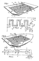
- thermo path 32 (figure 1). Both the resistance paths 7 and one or more thermo paths 32 are preferably crenellated or meander shaped to increase their length.
- a resistance path can however also take a rectangular form in order to obtain the greatest possible power transfer to the plate 2; the power transfer per surface is in any case bound to a maximum because of the properties of the enamel layer.
- thermo path 7 consists for example of screen-printed resistance paste having a low coefficient of resistance
- thermo path 32 consists for example of NTC or PTC paste having a high temperature coefficient.
- the pastes from the 7600/7700 Du Pont range are suitable for this purpose.
- the regulating member 20 is activated by an electrical signal originating from an operational amplifier 10, this electrical signal being a measure for the value of the temperature dependent resistance of thermo path 32 relative to the adjustable resistor 21 which is coupled to a thermostat knob (not shown).
- the operational amplifier 10 is biased by the bias resistors 22 and 23.
- thermo path 32 as well as resistance path 7 are crenellated in form, and in a way such that thermo path 32 is located in the vicinity of resistance path 7 so that regulation of the temperature takes place quickly.
- plate 2 is formed by a metal sole 12 of an unshown iron provided with an enamel layer 15.
- sole 12 is provided on both sides with NTC or PTC thermo paths, whereby the non-visible lower thermo paths 6 ⁇ can be connected via holes filled with conducting paste 8 and provided with an enamel layer 24 onto regulating circuit 5.
- thermo paths 6 ⁇ are located on the ironing surface of the metal plate 25 having a large heat capacity, so that the supply of heat to metal plate 25 has already got under way before a considerable discharge of heat through the insulating enamel layer to the object to be ironed from the metal plate takes place.
- the supply of current to electrical heating means 3 is regulated by a regulating member 11 which is controlled by electrical signals originating from two operational amplifiers 26, 27 (figure 4).
- Amplifiers 26, 27 are biased using resistors 28, 29 and 30 and using an adjustable resistor 31 connected onto an unshown thermostat knob, and amplify the temperature dependent resistance changes of respectively the lower thermo paths 6 ⁇ and the resistors 6.
- the regulating members 10 and 11 can for example be standard PID regulators suitable for one or two inputs.
- thermo paths 7 in the form of resistance paths 7 arranged between conducting strips 17 as well as a thermistor 6 in the form of thermo paths 32 arranged between conducting strips 33 can be applied onto a metal plate 16 provided with an enamel layer 15, with an intermediate insulating layer 13.
- Either the heating means 3 or thermistor 6 can hereby be embedded in the enamel layer, on the upper as well as on the lower part of for example a sole of an iron.
- heating device 1 is applied in so-called spot heating for manufacturing semi-conductor elements, whereby, by regulating the temperature of a plate 34 accurately from point to point, the viscosity and thereby the thickness of semi-conductor material (not shown) to be applied to plate 34 can be regulated.
- a plate 34 At each surface 35 are arranged an embedded resistance path 7 and a thermo path 32 using which the temperature of such a small surface can be accurately controlled with the aid of a control member 14 arranged at each surface.
- a central key board connected with control members 14 and secured on a frame 37, and associated electronics (not shown), the temperature of the surfaces 35 can be adjusted and measured, and these temperature values can be read on a dislay panel 38.
Landscapes
- Engineering & Computer Science (AREA)
- Food Science & Technology (AREA)
- Textile Engineering (AREA)
- Chemical & Material Sciences (AREA)
- Ceramic Engineering (AREA)
- Control Of Resistance Heating (AREA)
- Resistance Heating (AREA)
- Yarns And Mechanical Finishing Of Yarns Or Ropes (AREA)
- Baking, Grill, Roasting (AREA)
Claims (4)
Priority Applications (1)
| Application Number | Priority Date | Filing Date | Title |
|---|---|---|---|
| AT86200773T ATE61190T1 (de) | 1985-05-09 | 1986-05-02 | Heizvorrichtung. |
Applications Claiming Priority (2)
| Application Number | Priority Date | Filing Date | Title |
|---|---|---|---|
| NL8501327 | 1985-05-09 | ||
| NL8501327A NL8501327A (nl) | 1985-05-09 | 1985-05-09 | Verwarmingsinrichting voor het verwarmen van een lichaam. |
Publications (2)
| Publication Number | Publication Date |
|---|---|
| EP0201967A1 EP0201967A1 (fr) | 1986-11-20 |
| EP0201967B1 true EP0201967B1 (fr) | 1991-02-27 |
Family
ID=19845954
Family Applications (1)
| Application Number | Title | Priority Date | Filing Date |
|---|---|---|---|
| EP86200773A Expired - Lifetime EP0201967B1 (fr) | 1985-05-09 | 1986-05-02 | Dispositif de chauffage |
Country Status (4)
| Country | Link |
|---|---|
| EP (1) | EP0201967B1 (fr) |
| AT (1) | ATE61190T1 (fr) |
| DE (1) | DE3677634D1 (fr) |
| NL (1) | NL8501327A (fr) |
Cited By (1)
| Publication number | Priority date | Publication date | Assignee | Title |
|---|---|---|---|---|
| DE4109569A1 (de) * | 1991-03-22 | 1992-09-24 | Buchtal Gmbh | Elektrische heizplatte |
Families Citing this family (17)
| Publication number | Priority date | Publication date | Assignee | Title |
|---|---|---|---|---|
| CH674657A5 (en) * | 1988-02-04 | 1990-06-29 | Jura Elektroapparate Fab | Intrinsically safe electric iron - with centre of gravity turning heating plate away from horizontal position |
| IT1225119B (it) * | 1988-07-25 | 1990-11-02 | Zanussi A Spa Industrie | Dispositivo riscaldante per macchine lavatrici e/o asciugatricidi biancheria |
| EP0477394A1 (fr) * | 1990-09-24 | 1992-04-01 | Siemens Aktiengesellschaft | Dispositif de chauffage électrique avec un distributeur de la température prédéterminée, notamment pour détecteurs de gaz d'échappement |
| GB9024419D0 (en) * | 1990-11-09 | 1991-01-02 | Ist Lab Ltd | Heating apparatus |
| GB9115902D0 (en) * | 1991-07-23 | 1991-09-04 | Global Domestic Prod Ltd | Electrical heating elements |
| FR2680296B1 (fr) * | 1991-08-06 | 1994-07-01 | Deleage Pierre | Systeme de controle thermique d'au moins un element de chauffage electrique integre dans une paroi. |
| FR2686761B1 (fr) * | 1992-01-24 | 1994-05-27 | Seb Sa | Element chauffant a structure sandwich et appareil electromenager du type fer a repasser a vapeur comportant un tel element. |
| US5444228A (en) * | 1992-05-27 | 1995-08-22 | Seb S.A. | Flat, flexible heating element with integrated connector |
| GB2269980B (en) * | 1992-08-13 | 1996-07-03 | Ist Lab Ltd | Apparatus for heating liquid |
| GB9301884D0 (en) * | 1993-01-30 | 1993-03-17 | Global Domestic Prod Ltd | Peltier devices |
| US5475199A (en) * | 1993-12-22 | 1995-12-12 | Buchanan; R. Craig | Planar electric heater with enclosed U-shaped thick film heating element |
| EP0853239A3 (fr) * | 1997-01-13 | 2001-01-17 | Kabushiki Kaisha Riken | Detecteur de gaz et dispositif de chaufage |
| ES2129367B1 (es) * | 1997-08-12 | 2000-01-16 | Duque David Sanchez | Procedimiento para la fabricacion de paneles calefactores, y paneles obtenidos. |
| NL1009931C2 (nl) | 1998-08-24 | 2000-02-25 | Ferro Tech Bv | Inrichting voor het verwarmen van vloeistof, werkwijze voor het vervaardigen van de inrichting en een hulpstuk voor toepassing bij de werkwijze. |
| KR100577406B1 (ko) * | 2003-09-17 | 2006-05-10 | 박재상 | Pcb 방식을 이용한 히터 제조방법 및 히터 |
| ES2278539B1 (es) * | 2006-01-31 | 2008-07-16 | Celaya, Emparanza Y Galdos, Internacional, S.A. | Suela de plancha y plancha que la contiene. |
| TR2023004787A2 (tr) * | 2023-04-28 | 2023-05-22 | Univ Istanbul Gelisim | Pid kontrollü ütü |
Family Cites Families (7)
| Publication number | Priority date | Publication date | Assignee | Title |
|---|---|---|---|---|
| GB1102126A (en) * | 1964-02-24 | 1968-02-07 | Richards Morphy N I Ltd | Improvements relating to electric smoothing irons |
| DE1936245A1 (de) * | 1969-07-16 | 1971-02-04 | Beckman Instruments Gmbh | Infrarotstrahleranordnung |
| FR2189562A1 (fr) * | 1972-06-20 | 1974-01-25 | Zarzecki Jean | |
| DE2615064A1 (de) * | 1976-04-07 | 1977-10-20 | Husqvarna Ab | Kochpfanne mit elektronisch gesteuerter temperaturregelung und ein verfahren zur herstellung derselben |
| DE3117205A1 (de) * | 1981-04-30 | 1982-12-02 | Ernst Dipl.-Kfm. Dr. 7100 Heilbronn Haag | Optoelektronische kochfeldsteuerung |
| US4378489A (en) * | 1981-05-18 | 1983-03-29 | Honeywell Inc. | Miniature thin film infrared calibration source |
| DE3129862A1 (de) * | 1981-07-29 | 1983-02-17 | Licentia Patent-Verwaltungs-Gmbh, 6000 Frankfurt | Widerstandsanordnung |
-
1985
- 1985-05-09 NL NL8501327A patent/NL8501327A/nl not_active Application Discontinuation
-
1986
- 1986-05-02 EP EP86200773A patent/EP0201967B1/fr not_active Expired - Lifetime
- 1986-05-02 AT AT86200773T patent/ATE61190T1/de not_active IP Right Cessation
- 1986-05-02 DE DE8686200773T patent/DE3677634D1/de not_active Expired - Lifetime
Cited By (1)
| Publication number | Priority date | Publication date | Assignee | Title |
|---|---|---|---|---|
| DE4109569A1 (de) * | 1991-03-22 | 1992-09-24 | Buchtal Gmbh | Elektrische heizplatte |
Also Published As
| Publication number | Publication date |
|---|---|
| NL8501327A (nl) | 1986-12-01 |
| ATE61190T1 (de) | 1991-03-15 |
| EP0201967A1 (fr) | 1986-11-20 |
| DE3677634D1 (de) | 1991-04-04 |
Similar Documents
| Publication | Publication Date | Title |
|---|---|---|
| EP0201967B1 (fr) | Dispositif de chauffage | |
| EP0286217B1 (fr) | Bandes en film épais, à résistance électrique | |
| US6173619B1 (en) | Method and device for effecting temperature compensation in load cell type load detector | |
| US4041276A (en) | Electric fluid heating device | |
| US20230300951A1 (en) | Cooking device having a modular ceramic heater | |
| JPH02213733A (ja) | 電熱感知器 | |
| US3796858A (en) | Decorative aquarium heater | |
| US3651308A (en) | Automatic electric cooker | |
| US7057139B2 (en) | Electric heating assembly | |
| JP2007505300A (ja) | 加熱可能な赤外線センサと、赤外線センサを備える赤外線型体温計 | |
| EP0250079A1 (fr) | Régulateur de température d'un matelas à eau | |
| US2854548A (en) | Thermoresponsive switch means | |
| US1696684A (en) | Heater controller | |
| US3316374A (en) | Thermostat with an improved heat anticipation means | |
| US3064102A (en) | Thermoresponsive switch means | |
| GB2307629A (en) | Thick film electric heater: Control of supply | |
| US2943176A (en) | Control apparatus for a heating device | |
| US3096424A (en) | Temperature control means | |
| US1919068A (en) | Temperature regulator | |
| US2507964A (en) | Electrostatic heating | |
| GB2177271A (en) | Control means for electrical heating means of a cooker | |
| JP2816339B2 (ja) | 加熱装置 | |
| RU2043440C1 (ru) | Утюг с электронной системой управления | |
| JPS586697Y2 (ja) | 小型箔押機 | |
| JP2854018B2 (ja) | 電気コタツユニット |
Legal Events
| Date | Code | Title | Description |
|---|---|---|---|
| PUAI | Public reference made under article 153(3) epc to a published international application that has entered the european phase |
Free format text: ORIGINAL CODE: 0009012 |
|
| AK | Designated contracting states |
Kind code of ref document: A1 Designated state(s): AT BE CH DE FR GB IT LI LU NL SE |
|
| 17P | Request for examination filed |
Effective date: 19861205 |
|
| RAP1 | Party data changed (applicant data changed or rights of an application transferred) |
Owner name: FERRO (HOLLAND) B.V. Owner name: FERRO TECHNIEK B.V. |
|
| 17Q | First examination report despatched |
Effective date: 19881012 |
|
| ITF | It: translation for a ep patent filed | ||
| GRAA | (expected) grant |
Free format text: ORIGINAL CODE: 0009210 |
|
| AK | Designated contracting states |
Kind code of ref document: B1 Designated state(s): AT BE CH DE FR GB IT LI LU NL SE |
|
| REF | Corresponds to: |
Ref document number: 61190 Country of ref document: AT Date of ref document: 19910315 Kind code of ref document: T |
|
| REF | Corresponds to: |
Ref document number: 3677634 Country of ref document: DE Date of ref document: 19910404 |
|
| ET | Fr: translation filed | ||
| PLBE | No opposition filed within time limit |
Free format text: ORIGINAL CODE: 0009261 |
|
| STAA | Information on the status of an ep patent application or granted ep patent |
Free format text: STATUS: NO OPPOSITION FILED WITHIN TIME LIMIT |
|
| 26N | No opposition filed | ||
| EPTA | Lu: last paid annual fee | ||
| EAL | Se: european patent in force in sweden |
Ref document number: 86200773.9 |
|
| REG | Reference to a national code |
Ref country code: GB Ref legal event code: IF02 |
|
| PGFP | Annual fee paid to national office [announced via postgrant information from national office to epo] |
Ref country code: GB Payment date: 20030428 Year of fee payment: 18 |
|
| PGFP | Annual fee paid to national office [announced via postgrant information from national office to epo] |
Ref country code: LU Payment date: 20030528 Year of fee payment: 18 Ref country code: FR Payment date: 20030528 Year of fee payment: 18 Ref country code: AT Payment date: 20030528 Year of fee payment: 18 |
|
| PGFP | Annual fee paid to national office [announced via postgrant information from national office to epo] |
Ref country code: SE Payment date: 20030530 Year of fee payment: 18 Ref country code: NL Payment date: 20030530 Year of fee payment: 18 |
|
| PGFP | Annual fee paid to national office [announced via postgrant information from national office to epo] |
Ref country code: DE Payment date: 20030602 Year of fee payment: 18 Ref country code: BE Payment date: 20030602 Year of fee payment: 18 |
|
| PGFP | Annual fee paid to national office [announced via postgrant information from national office to epo] |
Ref country code: CH Payment date: 20030603 Year of fee payment: 18 |
|
| PG25 | Lapsed in a contracting state [announced via postgrant information from national office to epo] |
Ref country code: LU Free format text: LAPSE BECAUSE OF NON-PAYMENT OF DUE FEES Effective date: 20040502 Ref country code: GB Free format text: LAPSE BECAUSE OF NON-PAYMENT OF DUE FEES Effective date: 20040502 Ref country code: AT Free format text: LAPSE BECAUSE OF NON-PAYMENT OF DUE FEES Effective date: 20040502 |
|
| PG25 | Lapsed in a contracting state [announced via postgrant information from national office to epo] |
Ref country code: SE Free format text: LAPSE BECAUSE OF NON-PAYMENT OF DUE FEES Effective date: 20040503 |
|
| PG25 | Lapsed in a contracting state [announced via postgrant information from national office to epo] |
Ref country code: LI Free format text: LAPSE BECAUSE OF NON-PAYMENT OF DUE FEES Effective date: 20040531 Ref country code: CH Free format text: LAPSE BECAUSE OF NON-PAYMENT OF DUE FEES Effective date: 20040531 Ref country code: BE Free format text: LAPSE BECAUSE OF NON-PAYMENT OF DUE FEES Effective date: 20040531 |
|
| BERE | Be: lapsed |
Owner name: *FERRO (HOLLAND) B.V. Effective date: 20040531 Owner name: *FERRO TECHNIEK B.V. Effective date: 20040531 |
|
| PG25 | Lapsed in a contracting state [announced via postgrant information from national office to epo] |
Ref country code: NL Free format text: LAPSE BECAUSE OF NON-PAYMENT OF DUE FEES Effective date: 20041201 Ref country code: DE Free format text: LAPSE BECAUSE OF NON-PAYMENT OF DUE FEES Effective date: 20041201 |
|
| GBPC | Gb: european patent ceased through non-payment of renewal fee |
Effective date: 20040502 |
|
| EUG | Se: european patent has lapsed | ||
| REG | Reference to a national code |
Ref country code: CH Ref legal event code: PL |
|
| PG25 | Lapsed in a contracting state [announced via postgrant information from national office to epo] |
Ref country code: FR Free format text: LAPSE BECAUSE OF NON-PAYMENT OF DUE FEES Effective date: 20050131 |
|
| NLV4 | Nl: lapsed or anulled due to non-payment of the annual fee |
Effective date: 20041201 |
|
| REG | Reference to a national code |
Ref country code: FR Ref legal event code: ST |
|
| PG25 | Lapsed in a contracting state [announced via postgrant information from national office to epo] |
Ref country code: IT Free format text: LAPSE BECAUSE OF NON-PAYMENT OF DUE FEES Effective date: 20050502 |