EP0202402A2 - Abreuvoir pour porcelets - Google Patents
Abreuvoir pour porcelets Download PDFInfo
- Publication number
- EP0202402A2 EP0202402A2 EP86102760A EP86102760A EP0202402A2 EP 0202402 A2 EP0202402 A2 EP 0202402A2 EP 86102760 A EP86102760 A EP 86102760A EP 86102760 A EP86102760 A EP 86102760A EP 0202402 A2 EP0202402 A2 EP 0202402A2
- Authority
- EP
- European Patent Office
- Prior art keywords
- valve
- bore
- valve seat
- actuated
- ball
- Prior art date
- Legal status (The legal status is an assumption and is not a legal conclusion. Google has not performed a legal analysis and makes no representation as to the accuracy of the status listed.)
- Granted
Links
Images


Classifications
-
- A—HUMAN NECESSITIES
- A01—AGRICULTURE; FORESTRY; ANIMAL HUSBANDRY; HUNTING; TRAPPING; FISHING
- A01K—ANIMAL HUSBANDRY; AVICULTURE; APICULTURE; PISCICULTURE; FISHING; REARING OR BREEDING ANIMALS, NOT OTHERWISE PROVIDED FOR; NEW BREEDS OF ANIMALS
- A01K7/00—Watering equipment for stock or game
- A01K7/02—Automatic devices
- A01K7/06—Automatic devices actuated by the animal
Definitions
- the invention relates to a piglet drinking bowl according to the same preamble of the main claim as it is known from DE-OS 22 13 410.
- the valve leaves the water flow into the basin open for the duration of the actuation of an actuating lever acting on a valve tappet.
- the piglets tend to play with the operating lever, i.e. operate it longer and more often than is necessary to fill the drinking bowl with water. In addition to unnecessary water consumption, this leads to the piglet box becoming dirty.
- the invention has for its object to provide a piglet drinking bowl in which the amount of water escaping from the valve each time the operating lever is actuated is limited to a certain amount, as is already the case for a cattle drinking valve from DE-OS GM 84 04 184 is known.
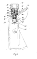
- the piglet basin is provided with a valve inserted into its body 36, which (FIG. 2) consists of a connecting piece 10, a blocking body 12, a valve seat 14, a valve tappet 16, a spacer 32, an O-ring 38, a sealing cap 40, a coil spring 42 and a sealing washer 44.
- a valve inserted into its body 36, which (FIG. 2) consists of a connecting piece 10, a blocking body 12, a valve seat 14, a valve tappet 16, a spacer 32, an O-ring 38, a sealing cap 40, a coil spring 42 and a sealing washer 44.
- the connector 10 is provided for connection to the water supply pipe at its upper portion with an internal thread and at its lower portion with an external thread, by means of which this is screwed into the body 36 of the piglet drinking bowl.
- a valve seat 14, which receives a valve tappet 16 is also inserted into the body 36 of the piglet drinking trough.
- This valve tappet 16 has an O-sealing ring 38 which produces a seal to the valve seat 14 and a cap 40, a spring 42 pulling the O-sealing ring 38 against the valve seat 14.
- valve tappet 16 When the actuating lever 46 is actuated, the valve tappet 16 is pushed upward against the force of the spring 42, as a result of which the cap 40 of the tappet 16 abuts the sealing ring 44 surrounding a bore 26 in the blocking body 12 and thus closes the bore 26.
- the 0-sealing ring 38 is lifted off the valve seat 14 so that a water flow from the space 30 defined by the upper ring surface of the valve seat 14 and the lower ring surface of the blocking body 12, the opening between the O-sealing ring 38 and the valve seat 14, past a flattened portion 48 of the plunger 16 from the drain hole 28 into the piglet basin.
- valve tappet 16 lowers again, the O-sealing ring 38 sits again on the valve seat 14 and seals the space 30 downward. Water flows through the bore 26 in the locking body 12 and fills the space 30 with water which can flow out the next time the actuating lever 46 is actuated.
- the two-stage structure of the valve is thus essential to the invention, the first valve stage in the exemplary embodiment shown being formed by a valve tappet 16 with a sealing ring 38 and a valve seat 14.
- the valve lifter 16 of this first valve stage is actuated, the bore 26 of the second valve stage is also closed.
- the water flow is only possible for a short time; the amount of water flowing out is essentially defined by the space 30 between the two valve stages.
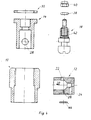
- the locking disk 12 is provided with a chamber 20 forming a bore which runs radially ver in the embodiment shown.
- This locking body 12 has an inlet bore 22, a first outlet bore 24 and a second outlet bore 26.
- the chamber 20 also receives a first ball 18 and a second ball 34, the first ball 18 blocking the second bore 26 in the rest position and the first bore 24 after actuation of the valve lifter 16.
- valve tappet 16 When the actuating lever 46 is actuated, the valve tappet 16 is pushed upward against the force of the spring 42, as a result of which the cap 40 of the tappet 16 abuts against the sealing ring 44 surrounding the second bore 26 and thus closes the second bore 26.
- the O-ring 38 is lifted off the valve seat 14 so that a water flow through the inlet bore 22, the chamber 20, the first bore 24, the space 30, the opening between the O-ring 38 and the valve seat 14 on a flat surface 48 of the plunger 16 over from the drain hole 28 into the piglet basin is possible.
- This water flow causes the first ball 18 in FIG. 1 to shift to the right into the conical end section of this chamber bore and thus to close the first bore 24.
- the water flowing off below causes a negative pressure in the first bore 24, which holds the ball 18 in a position blocking the first bore 24, as long as the valve lifter 16 blocks the second bore 26.
- the ball 18 then blocks the second bore 26. In this position, the first bore 24 is open again, but water leakage from the valve is prevented by the valve ring 16 of the valve tappet 16 seated on the valve seat 14.
- the second ball 34 serves to prevent the ball 18 from moving away from the second bore 26, so that when the valve lifter 16 is not actuated it blocks the second bore 26 and is thus held adjacent to the first bore 24.
- the chamber 20 does not have to be designed as a radial bore in the cylindrical valve piece 12, rather it can also be designed as an axial bore.
- the two outlet bores 24, 26 can also be arranged side by side.
- the second bore 26 is of very fine design, that is to say it allows only a small water flow.
- the function of this second bore 26 is only, after loosening the actuating lever 46 and lowering the plunger 16, to bring about pressure compensation in the space 30, which causes the ball 18 to fall off the first bore 24.
- the exemplary embodiment of the valve according to the invention for piglet drinking bowls shown is particularly simple to install, in that the first valve stage consisting of tappet 16 and valve seat 14 is inserted into a corresponding bore in the body 36 of the drinking bowl.
- the spacer ring 32 is then placed on the valve seat 14, the size of the space 30 and thus the amount of water flowing out when the actuating lever 46 is actuated being able to be influenced by the choice of the thickness of this spacer ring 32.
Landscapes
- Life Sciences & Earth Sciences (AREA)
- Environmental Sciences (AREA)
- Animal Husbandry (AREA)
- Biodiversity & Conservation Biology (AREA)
- Taps Or Cocks (AREA)
- Lift Valve (AREA)
- Devices For Dispensing Beverages (AREA)
- Mechanically-Actuated Valves (AREA)
Applications Claiming Priority (2)
| Application Number | Priority Date | Filing Date | Title |
|---|---|---|---|
| DE19853508537 DE3508537C1 (de) | 1985-03-09 | 1985-03-09 | Ferkeltraenkebecken |
| DE3508537 | 1985-03-09 |
Publications (3)
| Publication Number | Publication Date |
|---|---|
| EP0202402A2 true EP0202402A2 (fr) | 1986-11-26 |
| EP0202402A3 EP0202402A3 (en) | 1986-12-03 |
| EP0202402B1 EP0202402B1 (fr) | 1989-11-02 |
Family
ID=6264786
Family Applications (1)
| Application Number | Title | Priority Date | Filing Date |
|---|---|---|---|
| EP86102760A Expired EP0202402B1 (fr) | 1985-03-09 | 1986-03-03 | Abreuvoir pour porcelets |
Country Status (3)
| Country | Link |
|---|---|
| EP (1) | EP0202402B1 (fr) |
| DD (1) | DD253751A5 (fr) |
| DE (1) | DE3508537C1 (fr) |
Cited By (2)
| Publication number | Priority date | Publication date | Assignee | Title |
|---|---|---|---|---|
| GB2232335A (en) * | 1989-05-22 | 1990-12-12 | Clarke Brothers Limited | Liquid feeding system |
| GB2242109A (en) * | 1990-03-23 | 1991-09-25 | Hampshire Feeding Systems Ltd | Livestock liquid feed dispenser actuator |
Families Citing this family (4)
| Publication number | Priority date | Publication date | Assignee | Title |
|---|---|---|---|---|
| DE3744483A1 (de) * | 1987-02-20 | 1988-09-01 | Suevia Haiges Kg | Portionsdosierer fuer fluessigkeitsabgabeeirichtungen, insbesondere fuer tiertraenken |
| DE8702590U1 (de) * | 1987-02-20 | 1987-04-09 | Suevia Haiges GmbH & Co, 7125 Kirchheim | Portionsdosierer für Flüssigkeitsabgabeeinrichtungen, insbesondere für Tiertränken |
| US5148768A (en) * | 1991-10-18 | 1992-09-22 | Hinton Michele D | Pet house apparatus |
| DE9207693U1 (de) * | 1992-06-06 | 1992-08-20 | Suevia Haiges GmbH & Co, 7125 Kirchheim | Viehselbsttränkeinrichtung |
Family Cites Families (7)
| Publication number | Priority date | Publication date | Assignee | Title |
|---|---|---|---|---|
| DE2213410B2 (de) * | 1972-03-20 | 1981-04-09 | Suevia Haiges Kg, 7125 Kirchheim | Viehselbsttränkebecken |
| SE383089B (sv) * | 1972-07-31 | 1976-03-01 | J R Olde | Vattenautomat for djur |
| AU474113B2 (en) * | 1972-08-25 | 1975-02-27 | Nozzle for liquid dispenser | |
| DE2810110A1 (de) * | 1978-03-09 | 1979-09-13 | Suevia Haiges Kg | Selbsttraenkevorrichtung fuer tiere |
| DE8218670U1 (de) * | 1982-06-30 | 1982-10-07 | Suevia Haiges GmbH & Co, 7125 Kirchheim | Ventil fuer tiertraenken |
| SE8302924D0 (sv) * | 1983-05-24 | 1983-05-24 | Olde Jarl Rune | Anordning for utminutering av vetska till djur |
| DK160732C (da) * | 1983-12-02 | 1991-09-30 | Konrad Werner | Drikkeventil til dyr |
-
1985
- 1985-03-09 DE DE19853508537 patent/DE3508537C1/de not_active Expired
-
1986
- 1986-03-03 EP EP86102760A patent/EP0202402B1/fr not_active Expired
- 1986-03-07 DD DD28768786A patent/DD253751A5/de unknown
Cited By (2)
| Publication number | Priority date | Publication date | Assignee | Title |
|---|---|---|---|---|
| GB2232335A (en) * | 1989-05-22 | 1990-12-12 | Clarke Brothers Limited | Liquid feeding system |
| GB2242109A (en) * | 1990-03-23 | 1991-09-25 | Hampshire Feeding Systems Ltd | Livestock liquid feed dispenser actuator |
Also Published As
| Publication number | Publication date |
|---|---|
| EP0202402A3 (en) | 1986-12-03 |
| DE3508537C1 (de) | 1986-09-04 |
| EP0202402B1 (fr) | 1989-11-02 |
| DD253751A5 (de) | 1988-02-03 |
Similar Documents
| Publication | Publication Date | Title |
|---|---|---|
| EP0271765B1 (fr) | Soupape commandée par le fluide propre, déclenchable notamment par un électroaimant pilote | |
| DE3242945C2 (de) | Ventilanordnung | |
| DE2356326C2 (de) | Sanitäres Wasserventil | |
| EP0589836B1 (fr) | Clapet d'écoulement d'un réservoir de chasse d'eau | |
| EP0300280A1 (fr) | Soupape électromagnétique en particulier obturateur de distribution de fluides pour l'eau chaude | |
| EP0731230A2 (fr) | Soupape de remplissage pour réservoir de chasse d'eau | |
| EP0010310A2 (fr) | Soupape d'obturation pour le contrôle du niveau d'un liquide | |
| DE2940338A1 (de) | Waschbeckenarmatur | |
| DE3508537C1 (de) | Ferkeltraenkebecken | |
| DE4123610C2 (de) | Einstellbares Bedüsungsventil | |
| DE69104275T2 (de) | Hydrant mit Rückschlagventil. | |
| EP0112977A1 (fr) | Organe d'arrêt pour fluides agressifs | |
| DE3039677C2 (de) | Selbstschließende Auslaufarmatur | |
| DE3941153A1 (de) | Verbessertes drei- oder vierwegeventil | |
| DE4002852C2 (de) | Einloch-Mischbatterie mit ausziehbarer Handbrause | |
| DE3108791A1 (de) | Ablaufventil an einer sanitaeren einrichtung | |
| DE2047815A1 (de) | Entlüftungsventil | |
| DE3500564C1 (de) | Vorrichtung zum Auslösen des Wasserauslaufes bei einem geöffneten Wasserhahn | |
| DE3939224C2 (de) | Sanitäre Mischarmatur | |
| EP0716255B1 (fr) | Robinet sanitaire | |
| EP0957301A2 (fr) | Soupape d'arrêt pour fluides | |
| DE19850382A1 (de) | Vorrichtung zum Ablaß des in einem Bauteil eines Kraftfahrzeuges enthaltenen Öls | |
| WO1989005382A1 (fr) | Clapet de non-retour, notamment pour conduits d'eau potable | |
| DE3220951A1 (de) | Membranspuelventil | |
| EP3564451B1 (fr) | Réservoir de chasse d'eau pourvu de vanne de remplissage |
Legal Events
| Date | Code | Title | Description |
|---|---|---|---|
| PUAI | Public reference made under article 153(3) epc to a published international application that has entered the european phase |
Free format text: ORIGINAL CODE: 0009012 |
|
| PUAL | Search report despatched |
Free format text: ORIGINAL CODE: 0009013 |
|
| AK | Designated contracting states |
Kind code of ref document: A2 Designated state(s): FR GB IT SE |
|
| AK | Designated contracting states |
Kind code of ref document: A3 Designated state(s): FR GB IT SE |
|
| 17P | Request for examination filed |
Effective date: 19870520 |
|
| 17Q | First examination report despatched |
Effective date: 19880513 |
|
| GRAA | (expected) grant |
Free format text: ORIGINAL CODE: 0009210 |
|
| AK | Designated contracting states |
Kind code of ref document: B1 Designated state(s): FR GB IT SE |
|
| PG25 | Lapsed in a contracting state [announced via postgrant information from national office to epo] |
Ref country code: IT Free format text: LAPSE BECAUSE OF FAILURE TO SUBMIT A TRANSLATION OF THE DESCRIPTION OR TO PAY THE FEE WITHIN THE PRE;WARNING: LAPSES OF ITALIAN PATENTS WITH EFFECTIVE DATE BEFORE 2007 MAY HAVE OCCURRED AT ANY TIME BEFORE 2007. THE CORRECT EFFECTIVE DATE MAY BE DIFFERENT FROM THE ONE RECORDED.SCRIBED TIME-LIMIT Effective date: 19891102 Ref country code: SE Effective date: 19891102 |
|
| GBT | Gb: translation of ep patent filed (gb section 77(6)(a)/1977) | ||
| ET | Fr: translation filed | ||
| PG25 | Lapsed in a contracting state [announced via postgrant information from national office to epo] |
Ref country code: GB Effective date: 19900303 |
|
| PLBE | No opposition filed within time limit |
Free format text: ORIGINAL CODE: 0009261 |
|
| STAA | Information on the status of an ep patent application or granted ep patent |
Free format text: STATUS: NO OPPOSITION FILED WITHIN TIME LIMIT |
|
| 26N | No opposition filed | ||
| GBPC | Gb: european patent ceased through non-payment of renewal fee | ||
| PG25 | Lapsed in a contracting state [announced via postgrant information from national office to epo] |
Ref country code: FR Effective date: 19901130 |
|
| REG | Reference to a national code |
Ref country code: FR Ref legal event code: ST |