EP0202807B1 - Résonateur optique instable et laser - Google Patents
Résonateur optique instable et laser Download PDFInfo
- Publication number
- EP0202807B1 EP0202807B1 EP86303388A EP86303388A EP0202807B1 EP 0202807 B1 EP0202807 B1 EP 0202807B1 EP 86303388 A EP86303388 A EP 86303388A EP 86303388 A EP86303388 A EP 86303388A EP 0202807 B1 EP0202807 B1 EP 0202807B1
- Authority
- EP
- European Patent Office
- Prior art keywords
- resonator
- reflector
- central
- laser
- gas
- Prior art date
- Legal status (The legal status is an assumption and is not a legal conclusion. Google has not performed a legal analysis and makes no representation as to the accuracy of the status listed.)
- Expired - Lifetime
Links
- 230000003287 optical effect Effects 0.000 title claims abstract description 44
- 238000000605 extraction Methods 0.000 claims abstract description 17
- 230000005284 excitation Effects 0.000 claims description 11
- 239000002184 metal Substances 0.000 claims description 8
- 239000007787 solid Substances 0.000 claims description 5
- 238000001816 cooling Methods 0.000 claims description 3
- 239000007788 liquid Substances 0.000 claims description 2
- VNWKTOKETHGBQD-UHFFFAOYSA-N methane Chemical group C VNWKTOKETHGBQD-UHFFFAOYSA-N 0.000 claims 1
- 239000007789 gas Substances 0.000 description 25
- 238000010276 construction Methods 0.000 description 11
- CURLTUGMZLYLDI-UHFFFAOYSA-N Carbon dioxide Chemical compound O=C=O CURLTUGMZLYLDI-UHFFFAOYSA-N 0.000 description 6
- 230000005855 radiation Effects 0.000 description 6
- 230000003321 amplification Effects 0.000 description 3
- 229910002092 carbon dioxide Inorganic materials 0.000 description 3
- 238000003199 nucleic acid amplification method Methods 0.000 description 3
- 238000005086 pumping Methods 0.000 description 3
- XKRFYHLGVUSROY-UHFFFAOYSA-N Argon Chemical compound [Ar] XKRFYHLGVUSROY-UHFFFAOYSA-N 0.000 description 2
- IJGRMHOSHXDMSA-UHFFFAOYSA-N Atomic nitrogen Chemical compound N#N IJGRMHOSHXDMSA-UHFFFAOYSA-N 0.000 description 2
- 239000001569 carbon dioxide Substances 0.000 description 2
- 238000006243 chemical reaction Methods 0.000 description 2
- 238000010438 heat treatment Methods 0.000 description 2
- 239000001307 helium Substances 0.000 description 2
- 229910052734 helium Inorganic materials 0.000 description 2
- SWQJXJOGLNCZEY-UHFFFAOYSA-N helium atom Chemical compound [He] SWQJXJOGLNCZEY-UHFFFAOYSA-N 0.000 description 2
- 230000031700 light absorption Effects 0.000 description 2
- 238000000034 method Methods 0.000 description 2
- 239000000203 mixture Substances 0.000 description 2
- 239000011343 solid material Substances 0.000 description 2
- 229920000049 Carbon (fiber) Polymers 0.000 description 1
- 238000010521 absorption reaction Methods 0.000 description 1
- 230000001154 acute effect Effects 0.000 description 1
- 229910052786 argon Inorganic materials 0.000 description 1
- 230000000903 blocking effect Effects 0.000 description 1
- 239000004917 carbon fiber Substances 0.000 description 1
- 150000001875 compounds Chemical class 0.000 description 1
- 239000000110 cooling liquid Substances 0.000 description 1
- 230000008878 coupling Effects 0.000 description 1
- 238000010168 coupling process Methods 0.000 description 1
- 238000005859 coupling reaction Methods 0.000 description 1
- 230000003247 decreasing effect Effects 0.000 description 1
- 238000009826 distribution Methods 0.000 description 1
- 230000005670 electromagnetic radiation Effects 0.000 description 1
- 238000005516 engineering process Methods 0.000 description 1
- 239000000835 fiber Substances 0.000 description 1
- 239000011521 glass Substances 0.000 description 1
- 230000002452 interceptive effect Effects 0.000 description 1
- 150000002500 ions Chemical class 0.000 description 1
- 238000004519 manufacturing process Methods 0.000 description 1
- 229910052754 neon Inorganic materials 0.000 description 1
- GKAOGPIIYCISHV-UHFFFAOYSA-N neon atom Chemical compound [Ne] GKAOGPIIYCISHV-UHFFFAOYSA-N 0.000 description 1
- 229910052757 nitrogen Inorganic materials 0.000 description 1
- 230000001902 propagating effect Effects 0.000 description 1
- 239000010979 ruby Substances 0.000 description 1
- 229910001750 ruby Inorganic materials 0.000 description 1
- 238000004904 shortening Methods 0.000 description 1
- 238000003892 spreading Methods 0.000 description 1
- 239000000126 substance Substances 0.000 description 1
- 238000011144 upstream manufacturing Methods 0.000 description 1
Images


Classifications
-
- H—ELECTRICITY
- H01—ELECTRIC ELEMENTS
- H01S—DEVICES USING THE PROCESS OF LIGHT AMPLIFICATION BY STIMULATED EMISSION OF RADIATION [LASER] TO AMPLIFY OR GENERATE LIGHT; DEVICES USING STIMULATED EMISSION OF ELECTROMAGNETIC RADIATION IN WAVE RANGES OTHER THAN OPTICAL
- H01S3/00—Lasers, i.e. devices using stimulated emission of electromagnetic radiation in the infrared, visible or ultraviolet wave range
- H01S3/05—Construction or shape of optical resonators; Accommodation of active medium therein; Shape of active medium
- H01S3/08—Construction or shape of optical resonators or components thereof
-
- H—ELECTRICITY
- H01—ELECTRIC ELEMENTS
- H01S—DEVICES USING THE PROCESS OF LIGHT AMPLIFICATION BY STIMULATED EMISSION OF RADIATION [LASER] TO AMPLIFY OR GENERATE LIGHT; DEVICES USING STIMULATED EMISSION OF ELECTROMAGNETIC RADIATION IN WAVE RANGES OTHER THAN OPTICAL
- H01S3/00—Lasers, i.e. devices using stimulated emission of electromagnetic radiation in the infrared, visible or ultraviolet wave range
- H01S3/02—Constructional details
- H01S3/03—Constructional details of gas laser discharge tubes
- H01S3/036—Means for obtaining or maintaining the desired gas pressure within the tube, e.g. by gettering, replenishing; Means for circulating the gas, e.g. for equalising the pressure within the tube
-
- H—ELECTRICITY
- H01—ELECTRIC ELEMENTS
- H01S—DEVICES USING THE PROCESS OF LIGHT AMPLIFICATION BY STIMULATED EMISSION OF RADIATION [LASER] TO AMPLIFY OR GENERATE LIGHT; DEVICES USING STIMULATED EMISSION OF ELECTROMAGNETIC RADIATION IN WAVE RANGES OTHER THAN OPTICAL
- H01S3/00—Lasers, i.e. devices using stimulated emission of electromagnetic radiation in the infrared, visible or ultraviolet wave range
- H01S3/02—Constructional details
- H01S3/03—Constructional details of gas laser discharge tubes
- H01S3/038—Electrodes, e.g. special shape, configuration or composition
-
- H—ELECTRICITY
- H01—ELECTRIC ELEMENTS
- H01S—DEVICES USING THE PROCESS OF LIGHT AMPLIFICATION BY STIMULATED EMISSION OF RADIATION [LASER] TO AMPLIFY OR GENERATE LIGHT; DEVICES USING STIMULATED EMISSION OF ELECTROMAGNETIC RADIATION IN WAVE RANGES OTHER THAN OPTICAL
- H01S3/00—Lasers, i.e. devices using stimulated emission of electromagnetic radiation in the infrared, visible or ultraviolet wave range
- H01S3/02—Constructional details
- H01S3/04—Arrangements for thermal management
- H01S3/041—Arrangements for thermal management for gas lasers
Definitions
- the present invention relates to unstable optical resonators and to lasers.
- All known lasers comprise the following three fundamental elements: a lasing medium which provides atoms, ions, or molecules that support light amplification, an energy source to excite the medium, and an optical resonator to provide feedback of the amplified light.
- One of the most common lasing media in current use in lasers is gas. Solid state lasers are also abundant and employed in industrial application. A common source for exciting the lasing medium is an electrical discharge, though many other means for excitation are also available.
- optical resonators are of various shapes and constructions, as outlined in many publications such as those by M. W. Sasnett in "Comparing Industrial CO2 Lasers” in Lasers & Applications, September 1984, pages 85-90 or by W. G. Burnell in "Review of CW High-Power Laser Technology,” United Aircraft Research Laboratories - East Hartford, Connecticut, October 1973, UAR-M132.
- the optical resonators are constructed so as to provide for a high lasing volume and a high lasing mass. Constructions most common in gas lasers are of the "coaxial" type having a long and narrow shape such as a tube having two mirrors located at both ends, two electrodes located between the mirrors, and the gas being introduced into the tube so that it flows in the direction of the laser beam produced in the resonator.
- Such a construction has several disadvantages.
- the long distance between the mirrors makes it difficult to maintain an accurate permanent relative position between the mirrors, as is essential for the accurate operation of the laser.
- a further disadvantage derives from the large distance between the electrodes.
- the excitation voltage is proportional to distance and pressure, a laser operating with high lasing mass must use a very high excitation voltage, thereby causing many safety and technological problems.
- the high friction rate of the gas flowing along the walls of the tube increases its temperature and its staying time in the tube, thereby decreasing its lasing capability and requiring the application of a high power gas pump.
- lasers with other geometric constructions have been developed.
- One such construction is the so called "cross flow" construction wherein the resonator is defined by two mirrors of high surface area. The electrodes are coplanar with the mirrors, and the gas flows into the resonator perpendicularly to the direction of the laser beam.
- Such a construction allows for a significant shortening of the time of stay of the gas in the resonator.
- the electrical discharge will be higher at those zones where the electrical resistance is lower and the gas temperature is higher i.e., the lower lasing zones.
- the excitation of the lasing medium is not symmetric and therefore a non-symmetric laser beam is produced. Furthermore, the high temperature along the resonator causes non-uniformity in the beam output, thereby imparing the symmetry of the beam's cross section and mode.
- European Published Patent Application No. 0100089 discloses a laser having a resonator comprising, interalia, substantially conical reflective surfaces for the emission of the laser beam.
- the known resonator is of a long and a non-symmetric structure, having a plurality of reflectors, thereby infering a complexity in structure and operation.
- U.S. Patent 4,025,172 describes a compound unstable resonator comprising a pair of axially disposed rotationally symmetric mirrors and a centrally disposed conical folding mirror.
- the power extraction cavity is defined to have a generally cylindrical configuration and to lie intermediate the pair of rotationally symmetric mirrors and the folding mirrors.
- German Offenlegungsschrift 24 45 597 also describes an unstable resonator. In this configuration, the power extraction cavity is not rotationally symmetric.
- U.S. Patent 4,164,366 shows a resonator having a rotationally symmetric fold mirror and wherein the power extraction cavities are not rotationally symmetric.
- U.S. Patent No. 3,950,712 discloses an unstable optical resonator comprising: a substantially annular reflector disposed about and generally facing a central axis and comprising an annular reflecting surface; a central rotationally symmetric reflector positioned symmetrically along said central axis and comprising a conical central reflecting surface; and a rotationally symmetric power extraction cavity located between the annular reflector and the central reflector, the central reflector being arranged to reflect a portion of the light in the power extraction cavity out of the power extraction cavity as laser output.
- the unstable resonator cavity of which the power extraction cavity forms a part has an axial portion located between the central reflector and an end reflector spaced along the central axis.
- an unstable resonator as specified in the preamble to claim 1 is characterized in that the ends of the unstable resonator are defined by the annular reflector and the central reflector.
- optical axis there is defined a locus of optical axes extending between the annular reflector and the central reflector generally centrally of the power extraction cavity.
- the optical axes have a radial and, preferably, an axial component.
- this locus of optical axes is hereinafter termed "optical axis".
- the optical axis defines an angle ⁇ with respect to the central axis.
- the optical axis comprises an infinite number of optical axes extending between the annular reflector and the central reflector.
- the optical axis forms a planar ring surface when angle ⁇ equals 90 degrees or a curved surface of a truncated cone when angle ⁇ is smaller than 90 degrees.
- angle ⁇ equals 90 degrees
- a curved surface of a truncated cone when angle ⁇ is smaller than 90 degrees.
- optical axis represents the main direction of the beams between the annular reflector and the central reflector and it is normal to the center of an imaginary line connecting the edges of the annular reflector.
- the resonator may include means for connecting the annular reflector to the central reflector without interfering with optical beams passing therebetween.
- the rotationally symmetric central reflector is one of the components of the resonator that contributes to the emission of a rotationally symmetrical laser beam having a high power density and a small diameter, with mainly gaussian distribution.
- the conical surface of the present invention preferably is a narrow cone, i.e. a cone with a large height to base diameter ratio for minimal absorption of light and minimal heating of the central reflector.
- a narrow cone having large surface area can also be more effectively cooled than a broad short cone with small surface area.
- the applicant has found that a significant increase in the reflective area of the central rotationally symmetric reflector can be obtained if it is configured so that the narrow cone lies on top of a much wider truncated cone. It is preferable that at least one segment of the central reflector has a curved surface area.
- the optical axis is planar when angle ⁇ is equal to 90 degrees. However, it is preferable that angle ⁇ is different from 90 degrees in order to prevent an amplification of those rays travelling between the reflective surface of the annular reflector without hitting the central reflector. Such rays, if formed, would impair the intensity of the laser beam emitted from the resonator.
- angle ⁇ is in the range of 85 to 60 degrees.
- the position of the central refelctor relative to the substantially annular reflector is chosen so that the "optical axis" lies between the center of the annular reflector and the central reflector and is determined by angle ⁇ .
- the present invention also includes the use of the above described unstable resonator in lasers (Claims 7 - 9) and a gas laser apparatus (claim 10) employing the above described resonator in accordance with the present invention.
- the laser apparatus may comprise a laser or a laser amplifier.
- the laser apparatus is a gas laser such as a carbon dioxide laser, wherein a mixture of carbon dioxide, nitrogen and helium comprises the lasing medium.
- the laser can also use: other gases such as a mixture of helium and neon or argon or others; media produced by a chemical reaction in the so-called "chemical laser”; solid media such as Nd-YAG, ruby, glass and others; or liquid media.
- the excitation of the lasing medium can be carried out by any of the known methods, such as by electrical discharge (AC, DC or radio frequency), optical pumping, chemical reaction or any combination of those techniques.
- the excitation is preferably carried out by optical pumping such as by a flash lamp.
- the exitation is preferably carried out by means of electrical discharge.
- the electrodes to be used with the resonator are made of metal and shaped in a compact form, such as a dense net, a perforated metal sheet, or a honeycomb, in order to achieve the highest possible rate of excitation without blocking the gas flow through the electrodes.
- the electrodes can be made of carbon fibers in a "brush like" configuration, achieving high electrical concentration per unit area due to the very low thickness of the fibers.
- the electrodes may be positioned in the laser in such a way that their active surfaces lie parallel to the optical axis at both sides of the beam so that they do not interfere with the optical paths of the rays.
- both electrodes can be located on the same side of the beam, upstream of the gas flow.
- more than two electrodes may be employed in a configuration where two or more electrodes are located on one side of the beam and one or more electrodes are located on the other side of the beam.
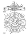
- the resonator 1 is defined by a substantially annular concave mirror 9 having reflective surface 9', and a central mirror 11 located along the central axis 17 of the resonator.
- a hollow cylinder 32 serves as a base for mirror 9 and is attached by several ribs 33 to cylindrical structure 31 which serves as a holder for mirror 11.
- the cylinder 32 and ribs 33 ensure that mirrors 9 and 11 form a concentric structure.
- Optical axis 18 is normal to annular mirror 9 and forms an acute angle ⁇ with the central axis 17.
- segment 13 of mirror 11 there is situated a segment 13 of mirror 11.
- the reflective surface area 13' of segment 13 has an annular convex shape having the same "optical axis" 18.
- Segment 13 is positioned on segment 12 of central mirror 11.
- the reflective surface 12' of segment 12 has a curved surface of a truncated cone perpendicular to the optical axis 18.
- cone segments 29 and 28 On top of segment 13 are situated cone segments 29 and 28. Segment 29 has the shape of a truncated cone, with reflective surface 29', and segment 28 has the shape of a full narrow cone, with reflective surface 28'.
- Electrodes 2 and 2' to be used in laser apparatus containing the resonator 1.
- the entire cross sectional view of the electrodes is not shown, but only the location of their schematic cross section.
- a part 55 of the gain medium excited by the electrodes 2 and 2' is indicated by reference numeral 55.
- resonator 1 is a confocal unstable resonator.
- the resonator has a large geometric magnification to provide for mode discrimination against higher order radial and azimuthal modes such that the lowest loss mode, typically the lowest order fundamental mode, is strongly favored.
- the resonator is a coverging-diverging optical system capable of expanding and compressing electromagnetic radiation circulating therein by repeated reflections between mirrors 9 and 13. In operation, the radiation within the resonator is compressed towards "optical axis" 18 by multiple reflections between the concave and convex surfaces of the mirrors into a diffraction dominated portion concentrated around optical axis 18 of the resonator.
- diffractive spreading causes the compressed inwardly propagating radiation to expand, which transforms the compressed radiation into outwardly propagation radiation, having a lowest loss mode, which fills the entire surface area of mirror 13.
- the radiation further expands to mirror 9 where it is reflected to mirror 29 and then to mirror 28 and leaves mirror 28 as a collimated beam of radiation having a circular cross section.
- Part of the beam reflects from mirror 9 to mirror 12 and repeats the same track until it also emerges from mirror 28 and out of the resonator.
- Amplification also takes place between mirror 9 and 11 because electrodes 2 and 2' supply energy for excitation of the lasing medium in the volume between the mirror and the electrodes.
- Figure 2 shows a top view of the resonator 1 of Figure 1.
- Ribs 33 attach central mirror 11 to cylinder 32 on which the concave mirror 9 with reflective surface 9' is situated.
- Figure 3 shows a schematic cross section of a gas laser incorporating the resonator of Figure 1, and two concentric electrodes 2 and 2' parallel to optical axis 18, all placed in enclosure 3.
- Enclosure 3 is of substantially cylindrical shape, its central axis being the central axis 17 of the resonator.
- a window 6 is provided to allow the laser beam to emerge from the upper segment of mirror 11.
- a blower 4 is provided for the circulation of the laser gas into and out of the resonator. Blower 4 is placed along central axis 17.
- Several heat exchange units fill most of the rest of the volume of the enclosure. In the figure, only one annular heat exchange unit 5 is shown. The exact location of the heat exchange units is not important.
- the heat exchange units are comprised of thin metal tubings (not shown in Figure 3) having high heat conduction; cooling liquid is circulated in the metal tubing to allow for cooling of the laser gas.
- the lasing gas in Figure 3 is circulated by blower 4 which causes the gas to pass through electrode 2', resonator 1, electrode 2, heat exchange unit 5 and back to blower 4.
- the gas flow is indicated by arrows 100.
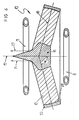
- FIG. 4 shows a cross sectional view of electrodes 2 and 2' when positioned in resonator 1. Electrodes 2 and 2' each have the shape of a curved surface of a truncated cone and they are concentrically located in mutually spaced relationship about central axis 17.
- Electrode 2 is located above the optical path of the rays reflected between concave mirror 9 and central mirror 11, while electrode 2' is located below the optical path. Electrodes 2 and 2' are parallel to the optical path of the beam.
- Figure 5 is a top view of Figure 4, showing, for the sake of clarity, only the top electrode 2 having a net structure composed of radial metal wires 36 and concentric metal wires 37. There is a space 38 between the bottom edge 40 of the electrode and mirror 9 and a space 39 between the inner upper edge 41 of the electrode and mirror 11. Those spaces are necessary in order to prevent arcing between the electrodes and the metal surfaces of the mirrors.
- FIG 6 is a schematic cross sectional view of a solid state laser resonator 19 in accordance with the present invention.
- Resonator 19 has an annular mirror 20 having reflective surface 20' and a central mirror 11 positioned so that optical axis 18 forms angle ⁇ with the central axis 17.
- Mirror 11 has the same configuration as mirror 11 in Figure 1.
- the lasing medium 10 is of solid material such as Nd-Yag, and it fills the volume between mirror 20 and mirror 11.
- the optical path of rays in the resonator is identical to the optical path of rays in Figure 1 and the beam emerging from resonator 19, defined by extreme rays 14 and 27, has a circular cross section. Also shown schematically in Figure 6 are two annular flash lamps 7 and 8, used for the optical pumping of the lasing medium 10. The flash lamps are located out of the optical path of the beam.
Landscapes
- Physics & Mathematics (AREA)
- Electromagnetism (AREA)
- Engineering & Computer Science (AREA)
- Plasma & Fusion (AREA)
- Optics & Photonics (AREA)
- Lasers (AREA)
Claims (15)
- Résonateur optique instable (1) comprenant :
un réflecteur sensiblement annulaire (9) placé autour d'un axe central (17) et en face de celui-ci de manière générale, et comprenant au moins une surface réfléchissante annulaire (9'),
un réflecteur central (11) à symétrie de rotation, disposé symétriquement le long de l'axe central (17) et comprenant au moins une surface centrale conique réfléchissante (12', 13', 28', 29'), et
une cavité d'extraction d'énergie à symétrie de rotation, placée entre le réflecteur annulaire (9) et le réflecteur central (11), le réflecteur central (11) étant disposé afin qu'il réfléchisse une partie de la lumière de la cavité d'extraction d'énergie en dehors de cette cavité sous forme du faisceau de sortie du laser,
caractérisé en ce que les extrémités du résonateur instable sont délimitées par le réflecteur annulaire (9) et le réflecteur central (11). - Résonateur selon la revendication 1, dans lequel le lieu des axes optiques (18), ayant une composante radiale et disposés entre le réflecteur annulaire (9) et le réflecteur central (11), au centre de façon générale de la cavité d'extraction d'énergie, délimite une surface courbe de tronc de cône.
- Résonateur selon la revendication 1 ou 2, comprenant en outre un dispositif (33) placé à l'extérieur de la cavité d'extraction d'énergie et qui raccorde le réflecteur annulaire (9) au réflecteur central (11).
- Résonateur selon l'une quelconque des revendications 1 à 3, dans lequel le réflecteur central (11) est un cône (28) monté sur deux troncs de cône (12, 29).
- Résonateur selon l'une quelconque des revendications 1 à 4, dans lequel le réflecteur annulaire (9) a une courbure concave et une surface réfléchissante centrale (13') est une surface à courbure convexe.
- Résonateur selon la revendication 2, dans lequel l'angle de l'axe central (17) et des axes optiques (18) est compris entre 60 et 85°.
- Application d'un résonateur (1) selon l'une quelconque des revendications 1 à 6 à un laser à gaz.
- Application d'un résonateur (1) selon l'une quelconque des revendications 1 à 6 à un laser à liquide.
- Application d'un résonateur (1) selon l'une quelconque des revendications 1 à 6 à un laser à l'état solide.
- Appareil laser à gaz, comprenant :
un résonateur instable (1) selon la revendication 1,
une paire d'électrodes (2, 2') placées autour de l'axe central (17) du résonateur et concentriques à cet axe, les électrodes étant positionnées radialement à l'extérieur du réflecteur central (11) mais radialement à l'intérieur du réflecteur annulaire (9), à l'extérieur de la cavité d'extraction d'énergie et parallèlement à un lieu des axes optiques (18) ayant une composante radiale et disposé entre le réflecteur annulaire (9) et le réflecteur central (11) au centre de façon générale de la cavité d'extraction d'énergie,
une enceinte (3) ayant une fenêtre (6) placée en face du sommet d'une surface centrale conique réfléchissante (28') du réflecteur central (11),
un dispositif (4) destiné à déplacer un gaz actif pour l'effet laser dans le résonateur (1) avec une direction de circulation parallèle de façon générale à l'axe central (17) du résonateur, et
un dispositif (5) de refroidissement du gaz actif pour l'effet laser dans l'enceinte (3). - Appareil laser selon la revendication 10, dans lequel les électrodes (2, 2') sont formées d'un métal et sont perforées afin qu'elles permettent un écoulement du gaz du laser.
- Appareil laser selon la revendication 10, dans lequel les électrodes (2, 2') sont formées d'une structure à fibres de carbone.
- Appareil à laser selon l'une quelconque des revendications 10 à 12, comprenant en outre un dispositif d'excitation comprenant un dispositif d'excitation continue, alternative ou à haute fréquence ou toute combinaison de tels dispositifs.
- Appareil laser selon l'une quelconque des revendications 10 à 13, dans lequel le dispositif (5) de refroidissement du gaz du laser comprend des unités d'échange de chaleur disposées dans l'enceinte (3).
- Appareil laser selon l'une quelconque des revendications 10 à 14, dans lequel le dispositif (4) de déplacement de gaz comprend un ventilateur (4) à gaz placé dans l'enceinte (3) pratiquement le long de l'axe central (17) du résonateur (1).
Priority Applications (1)
| Application Number | Priority Date | Filing Date | Title |
|---|---|---|---|
| AT86303388T ATE93999T1 (de) | 1985-05-07 | 1986-05-02 | Instabiler optischer resonator und laser. |
Applications Claiming Priority (2)
| Application Number | Priority Date | Filing Date | Title |
|---|---|---|---|
| IL75117A IL75117A (en) | 1985-05-07 | 1985-05-07 | Symmetrical optical resonator and laser comprising same |
| IL75117 | 1985-05-07 |
Publications (2)
| Publication Number | Publication Date |
|---|---|
| EP0202807A1 EP0202807A1 (fr) | 1986-11-26 |
| EP0202807B1 true EP0202807B1 (fr) | 1993-09-01 |
Family
ID=11055882
Family Applications (1)
| Application Number | Title | Priority Date | Filing Date |
|---|---|---|---|
| EP86303388A Expired - Lifetime EP0202807B1 (fr) | 1985-05-07 | 1986-05-02 | Résonateur optique instable et laser |
Country Status (8)
| Country | Link |
|---|---|
| US (1) | US4780882A (fr) |
| EP (1) | EP0202807B1 (fr) |
| JP (1) | JPH0654818B2 (fr) |
| KR (1) | KR900000837B1 (fr) |
| AT (1) | ATE93999T1 (fr) |
| CA (1) | CA1277757C (fr) |
| DE (1) | DE3688947T2 (fr) |
| IL (1) | IL75117A (fr) |
Families Citing this family (9)
| Publication number | Priority date | Publication date | Assignee | Title |
|---|---|---|---|---|
| US4952599A (en) * | 1987-07-29 | 1990-08-28 | Ciba-Geigy Corporation | Phenylthioureas, phenylisothioureas, phenylcarbodiimides, pesticidal compositions containing them and their use in pest control |
| US5327449A (en) * | 1988-04-22 | 1994-07-05 | Fraunhoefer-Gesellschaft Zur Foerderung Der Angewandten Forschung E.V. | Laser resonator |
| US5063806A (en) * | 1990-06-28 | 1991-11-12 | Mayfield Alfred B | Anti-kick forward device for radial arm saws |
| DE4203225C2 (de) * | 1992-02-05 | 1994-06-09 | Deutsche Forsch Luft Raumfahrt | Wellenleiterlaser |
| JPH07307506A (ja) * | 1994-05-16 | 1995-11-21 | Mitsubishi Electric Corp | レーザ発振器 |
| JP4834351B2 (ja) | 2005-08-22 | 2011-12-14 | 株式会社東芝 | 文字認識装置及び文字認識方法 |
| JP2007059591A (ja) * | 2005-08-24 | 2007-03-08 | Mitsubishi Heavy Ind Ltd | 光励起ディスク型固体レーザ共振器、光励起ディスク型固体レーザシステム |
| US7773641B2 (en) * | 2007-12-20 | 2010-08-10 | Mitsubishi Heavy Industries, Ltd. | Optically pumped disk-type solid state laser oscillator and optically pumped disk-type solid state laser system |
| US12444897B2 (en) | 2019-07-31 | 2025-10-14 | IDEA machine development design AND production ltd. | Disc laser |
Citations (1)
| Publication number | Priority date | Publication date | Assignee | Title |
|---|---|---|---|---|
| US3950712A (en) * | 1975-04-14 | 1976-04-13 | United Technologies Corporation | Unstable laser resonator having radial propagation |
Family Cites Families (7)
| Publication number | Priority date | Publication date | Assignee | Title |
|---|---|---|---|---|
| US3909744A (en) * | 1973-09-24 | 1975-09-30 | United Technologies Corp | Unstable resonator system producing a high irradiance beam in the far field |
| US3921096A (en) * | 1974-12-16 | 1975-11-18 | United Technologies Corp | Unstable split mode laser resonator |
| US4025172A (en) * | 1975-10-09 | 1977-05-24 | United Technologies Corporation | Compound unstable resonator |
| US4050036A (en) * | 1976-02-25 | 1977-09-20 | Textron Inc. | Optical system for lasers |
| US4164366A (en) * | 1977-11-04 | 1979-08-14 | United Technologies Corporation | Variable output coupled resonator |
| US4342115A (en) * | 1980-10-06 | 1982-07-27 | United Technologies Corporation | Laser discharge electrode configuration |
| FR2531282A2 (fr) * | 1982-07-30 | 1984-02-03 | Comp Generale Electricite | Oscillateur laser a flux gazeux |
-
1985
- 1985-05-07 IL IL75117A patent/IL75117A/xx unknown
-
1986
- 1986-05-02 DE DE86303388T patent/DE3688947T2/de not_active Expired - Fee Related
- 1986-05-02 EP EP86303388A patent/EP0202807B1/fr not_active Expired - Lifetime
- 1986-05-02 AT AT86303388T patent/ATE93999T1/de active
- 1986-05-06 KR KR1019860003514A patent/KR900000837B1/ko not_active Expired
- 1986-05-07 JP JP61105765A patent/JPH0654818B2/ja not_active Expired - Lifetime
- 1986-05-07 CA CA000508576A patent/CA1277757C/fr not_active Expired - Lifetime
-
1988
- 1988-01-05 US US07/140,962 patent/US4780882A/en not_active Expired - Fee Related
Patent Citations (1)
| Publication number | Priority date | Publication date | Assignee | Title |
|---|---|---|---|---|
| US3950712A (en) * | 1975-04-14 | 1976-04-13 | United Technologies Corporation | Unstable laser resonator having radial propagation |
Also Published As
| Publication number | Publication date |
|---|---|
| IL75117A0 (en) | 1985-09-29 |
| JPS61281569A (ja) | 1986-12-11 |
| KR900000837B1 (ko) | 1990-02-17 |
| IL75117A (en) | 1990-08-31 |
| DE3688947T2 (de) | 1993-12-16 |
| CA1277757C (fr) | 1990-12-11 |
| ATE93999T1 (de) | 1993-09-15 |
| US4780882A (en) | 1988-10-25 |
| DE3688947D1 (de) | 1993-10-07 |
| KR860009513A (ko) | 1986-12-23 |
| JPH0654818B2 (ja) | 1994-07-20 |
| EP0202807A1 (fr) | 1986-11-26 |
Similar Documents
| Publication | Publication Date | Title |
|---|---|---|
| US4500998A (en) | Gas laser | |
| US4719639A (en) | Carbon dioxide slab laser | |
| EP0202807B1 (fr) | Résonateur optique instable et laser | |
| GB2117558A (en) | High power fundamental mode laser | |
| US4520486A (en) | Gas flow laser oscillator | |
| EP0098143A2 (fr) | Structure combinée de résonateur/laser | |
| US20030058913A1 (en) | CO2 slab laser having electrode assembly including ventilated insulators | |
| US5867519A (en) | Multiple element, folded beam laser | |
| US4945547A (en) | Laser beam processing apparatus | |
| EP0986150B1 (fr) | Laser à faisceau replie et à éléments multiples | |
| US5131004A (en) | RF excited CO2 slab waveguide laser | |
| US4397023A (en) | High efficiency dye laser | |
| WO1998006156A9 (fr) | Laser a faisceau replie et a elements multiples | |
| US6879616B2 (en) | Diffusion-cooled laser system | |
| US20020105993A1 (en) | Pulsed discharge gas laser having non-integral supply reservoir | |
| JPS5923582A (ja) | 気体導波管レ−ザ発生器 | |
| US5867518A (en) | Multiple element laser pumping chamber | |
| US12444897B2 (en) | Disc laser | |
| JP2833219B2 (ja) | ガスレーザ発振装置 | |
| KR100272847B1 (ko) | 레이저발진기 | |
| CA1067190A (fr) | Systeme optique de formation d'images de decharges lumineuses dans un laser | |
| JPH0786667A (ja) | 円環状回転対称レ−ザ発振器 | |
| HODGSON | Beam Quality and Efficiency of Annular Gain Lasers | |
| JPH08191164A (ja) | 固体レーザ | |
| JPH02125481A (ja) | 気体レーザ装置 |
Legal Events
| Date | Code | Title | Description |
|---|---|---|---|
| PUAI | Public reference made under article 153(3) epc to a published international application that has entered the european phase |
Free format text: ORIGINAL CODE: 0009012 |
|
| AK | Designated contracting states |
Kind code of ref document: A1 Designated state(s): AT BE CH DE FR GB IT LI LU NL SE |
|
| 17P | Request for examination filed |
Effective date: 19870518 |
|
| 17Q | First examination report despatched |
Effective date: 19890922 |
|
| RTI1 | Title (correction) | ||
| RAP1 | Party data changed (applicant data changed or rights of an application transferred) |
Owner name: THE WELDING INSTITUTE |
|
| GRAA | (expected) grant |
Free format text: ORIGINAL CODE: 0009210 |
|
| AK | Designated contracting states |
Kind code of ref document: B1 Designated state(s): AT BE CH DE FR GB IT LI LU NL SE |
|
| PG25 | Lapsed in a contracting state [announced via postgrant information from national office to epo] |
Ref country code: NL Effective date: 19930901 Ref country code: LI Effective date: 19930901 Ref country code: CH Effective date: 19930901 Ref country code: BE Effective date: 19930901 Ref country code: AT Effective date: 19930901 |
|
| REF | Corresponds to: |
Ref document number: 93999 Country of ref document: AT Date of ref document: 19930915 Kind code of ref document: T |
|
| REF | Corresponds to: |
Ref document number: 3688947 Country of ref document: DE Date of ref document: 19931007 |
|
| ITF | It: translation for a ep patent filed | ||
| REG | Reference to a national code |
Ref country code: CH Ref legal event code: PL |
|
| ET | Fr: translation filed | ||
| NLV1 | Nl: lapsed or annulled due to failure to fulfill the requirements of art. 29p and 29m of the patents act | ||
| PG25 | Lapsed in a contracting state [announced via postgrant information from national office to epo] |
Ref country code: GB Effective date: 19940502 |
|
| PG25 | Lapsed in a contracting state [announced via postgrant information from national office to epo] |
Ref country code: SE Effective date: 19940503 |
|
| PG25 | Lapsed in a contracting state [announced via postgrant information from national office to epo] |
Ref country code: LU Free format text: LAPSE BECAUSE OF NON-PAYMENT OF DUE FEES Effective date: 19940531 |
|
| PLBE | No opposition filed within time limit |
Free format text: ORIGINAL CODE: 0009261 |
|
| STAA | Information on the status of an ep patent application or granted ep patent |
Free format text: STATUS: NO OPPOSITION FILED WITHIN TIME LIMIT |
|
| 26N | No opposition filed | ||
| GBPC | Gb: european patent ceased through non-payment of renewal fee |
Effective date: 19940502 |
|
| EUG | Se: european patent has lapsed |
Ref document number: 86303388.2 Effective date: 19941210 |
|
| PG25 | Lapsed in a contracting state [announced via postgrant information from national office to epo] |
Ref country code: FR Effective date: 19950131 |
|
| PG25 | Lapsed in a contracting state [announced via postgrant information from national office to epo] |
Ref country code: DE Effective date: 19950201 |
|
| EUG | Se: european patent has lapsed |
Ref document number: 86303388.2 |
|
| REG | Reference to a national code |
Ref country code: FR Ref legal event code: ST |
|
| PG25 | Lapsed in a contracting state [announced via postgrant information from national office to epo] |
Ref country code: IT Free format text: LAPSE BECAUSE OF NON-PAYMENT OF DUE FEES Effective date: 20050502 |