EP0202924A2 - Schlägerrahmen mit Löchern für die Bespannung sowie Verfahren zu dessen Herstellung - Google Patents
Schlägerrahmen mit Löchern für die Bespannung sowie Verfahren zu dessen Herstellung Download PDFInfo
- Publication number
- EP0202924A2 EP0202924A2 EP86303841A EP86303841A EP0202924A2 EP 0202924 A2 EP0202924 A2 EP 0202924A2 EP 86303841 A EP86303841 A EP 86303841A EP 86303841 A EP86303841 A EP 86303841A EP 0202924 A2 EP0202924 A2 EP 0202924A2
- Authority
- EP
- European Patent Office
- Prior art keywords
- mold
- action devices
- principal
- fibers
- head
- Prior art date
- Legal status (The legal status is an assumption and is not a legal conclusion. Google has not performed a legal analysis and makes no representation as to the accuracy of the status listed.)
- Withdrawn
Links
Images


Classifications
-
- B—PERFORMING OPERATIONS; TRANSPORTING
- B29—WORKING OF PLASTICS; WORKING OF SUBSTANCES IN A PLASTIC STATE IN GENERAL
- B29C—SHAPING OR JOINING OF PLASTICS; SHAPING OF MATERIAL IN A PLASTIC STATE, NOT OTHERWISE PROVIDED FOR; AFTER-TREATMENT OF THE SHAPED PRODUCTS, e.g. REPAIRING
- B29C70/00—Shaping composites, i.e. plastics material comprising reinforcements, fillers or preformed parts, e.g. inserts
- B29C70/04—Shaping composites, i.e. plastics material comprising reinforcements, fillers or preformed parts, e.g. inserts comprising reinforcements only, e.g. self-reinforcing plastics
- B29C70/28—Shaping operations therefor
- B29C70/40—Shaping or impregnating by compression not applied
- B29C70/42—Shaping or impregnating by compression not applied for producing articles of definite length, i.e. discrete articles
- B29C70/46—Shaping or impregnating by compression not applied for producing articles of definite length, i.e. discrete articles using matched moulds, e.g. for deforming sheet moulding compounds [SMC] or prepregs
- B29C70/48—Shaping or impregnating by compression not applied for producing articles of definite length, i.e. discrete articles using matched moulds, e.g. for deforming sheet moulding compounds [SMC] or prepregs and impregnating the reinforcements in the closed mould, e.g. resin transfer moulding [RTM], e.g. by vacuum
-
- B—PERFORMING OPERATIONS; TRANSPORTING
- B29—WORKING OF PLASTICS; WORKING OF SUBSTANCES IN A PLASTIC STATE IN GENERAL
- B29C—SHAPING OR JOINING OF PLASTICS; SHAPING OF MATERIAL IN A PLASTIC STATE, NOT OTHERWISE PROVIDED FOR; AFTER-TREATMENT OF THE SHAPED PRODUCTS, e.g. REPAIRING
- B29C70/00—Shaping composites, i.e. plastics material comprising reinforcements, fillers or preformed parts, e.g. inserts
-
- A—HUMAN NECESSITIES
- A63—SPORTS; GAMES; AMUSEMENTS
- A63B—APPARATUS FOR PHYSICAL TRAINING, GYMNASTICS, SWIMMING, CLIMBING, OR FENCING; BALL GAMES; TRAINING EQUIPMENT
- A63B49/00—Stringed rackets, e.g. for tennis
- A63B49/02—Frames
- A63B49/022—String guides on frames, e.g. grommets
-
- B—PERFORMING OPERATIONS; TRANSPORTING
- B29—WORKING OF PLASTICS; WORKING OF SUBSTANCES IN A PLASTIC STATE IN GENERAL
- B29C—SHAPING OR JOINING OF PLASTICS; SHAPING OF MATERIAL IN A PLASTIC STATE, NOT OTHERWISE PROVIDED FOR; AFTER-TREATMENT OF THE SHAPED PRODUCTS, e.g. REPAIRING
- B29C45/00—Injection moulding, i.e. forcing the required volume of moulding material through a nozzle into a closed mould; Apparatus therefor
- B29C45/14—Injection moulding, i.e. forcing the required volume of moulding material through a nozzle into a closed mould; Apparatus therefor incorporating preformed parts or layers, e.g. injection moulding around inserts or for coating articles
- B29C45/14336—Coating a portion of the article, e.g. the edge of the article
- B29C45/14344—Moulding in or through a hole in the article, e.g. outsert moulding
-
- B—PERFORMING OPERATIONS; TRANSPORTING
- B29—WORKING OF PLASTICS; WORKING OF SUBSTANCES IN A PLASTIC STATE IN GENERAL
- B29C—SHAPING OR JOINING OF PLASTICS; SHAPING OF MATERIAL IN A PLASTIC STATE, NOT OTHERWISE PROVIDED FOR; AFTER-TREATMENT OF THE SHAPED PRODUCTS, e.g. REPAIRING
- B29C45/00—Injection moulding, i.e. forcing the required volume of moulding material through a nozzle into a closed mould; Apparatus therefor
- B29C45/14—Injection moulding, i.e. forcing the required volume of moulding material through a nozzle into a closed mould; Apparatus therefor incorporating preformed parts or layers, e.g. injection moulding around inserts or for coating articles
- B29C45/14778—Injection moulding, i.e. forcing the required volume of moulding material through a nozzle into a closed mould; Apparatus therefor incorporating preformed parts or layers, e.g. injection moulding around inserts or for coating articles the article consisting of a material with particular properties, e.g. porous, brittle
- B29C45/14786—Fibrous material or fibre containing material, e.g. fibre mats or fibre reinforced material
-
- B—PERFORMING OPERATIONS; TRANSPORTING
- B29—WORKING OF PLASTICS; WORKING OF SUBSTANCES IN A PLASTIC STATE IN GENERAL
- B29C—SHAPING OR JOINING OF PLASTICS; SHAPING OF MATERIAL IN A PLASTIC STATE, NOT OTHERWISE PROVIDED FOR; AFTER-TREATMENT OF THE SHAPED PRODUCTS, e.g. REPAIRING
- B29C70/00—Shaping composites, i.e. plastics material comprising reinforcements, fillers or preformed parts, e.g. inserts
- B29C70/04—Shaping composites, i.e. plastics material comprising reinforcements, fillers or preformed parts, e.g. inserts comprising reinforcements only, e.g. self-reinforcing plastics
- B29C70/28—Shaping operations therefor
- B29C70/54—Component parts, details or accessories; Auxiliary operations, e.g. feeding or storage of prepregs or SMC after impregnation or during ageing
- B29C70/545—Perforating, cutting or machining during or after moulding
-
- B—PERFORMING OPERATIONS; TRANSPORTING
- B29—WORKING OF PLASTICS; WORKING OF SUBSTANCES IN A PLASTIC STATE IN GENERAL
- B29C—SHAPING OR JOINING OF PLASTICS; SHAPING OF MATERIAL IN A PLASTIC STATE, NOT OTHERWISE PROVIDED FOR; AFTER-TREATMENT OF THE SHAPED PRODUCTS, e.g. REPAIRING
- B29C2793/00—Shaping techniques involving a cutting or machining operation
- B29C2793/0045—Perforating
Definitions
- This invention relates to racquets for use in games such as tennis, squash, racquetball and the like.
- the invention is more particularly concerned with methods of making fiber-reinforced molded racquet frames.
- a method of making a fiber-reinforced molded racquet frame comprising: placing a core including a tube comprising at least one layer of woven reinforcing fibers in a mold shaped to define the frame; providing, as a portion of the mold, a plurality of side-action devices each including at least one needle-like projection; closing the mold; piercing with the projections the weave of the woven reinforcing fibers and the remainder of the core and extending the projections across the mold--cavity to define respective stringing-holes passing radially through the molded frame; and injecting a plastics material into the mold around the core and the needle-like projections.
- the plastics material has a relatively low setting temperature and a relatively low viscosity, such as a methacrylate-based resin.
- the core comprises a plastics foam core member, preferably an extruded polyethylene foam core member, disposed inside the tube of reinforcing fibers, in which case the method can advantageously further include the step of weaving the tube of reinforcing fibers, preferably in the form of a braid, around the core member.
- the reinforcing fibers can be carbon fibers, boron fibers, glass fibers, silicon carbide fibers, ceramic fibers, or aramid fibers of the kind available under the trade name Kevlar, or any combination of these.
- a mold for molding a racquet frame comprising:
- the first surface portion of the principal mold member defines the radially inwardly facing surface of the part of the head, while the respective first surface portions of the side-action devices together define the radially outwardly facing surface of the part of the head.
- the principal mold member comprises first and second mold plates detachably secured together.
- the first surface portion of the principal mold member is preferably on the first mold plate
- the second mold plate preferalby has a surface portion which defines one of the surfaces of the part of the head which faces generally perpendicularly to the plane of the head.
- the first mold plate preferably has another surface portion which defines the other of the generally perpendicularly facing surfaces of the part of the head.
- the mold plates preferably have spaced parallel surfaces which surround the mold cavity and between which the side-action devices are slidably- located.
- each side-action device engages guide means, for example a groove, provided in at least one of the spaced parallel surface of the mold plates to constrain the side-action device to move parallel to the axis of its projection.
- each of said side-action devices has a plurality of the projections extending parallel to each other.
- the invention also includes racquet frames made by method in accordance with the first aspect of the invention, particularly in molds in accordance with the second aspect of the invention, and racquets incorporating such frames.
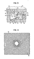
- Mold 10 includes a principal mold member, comprising first and second mold plates 12 and 14, respectively, and a plurality of side-action devices 34. Mold plates 12, 14 are detachably secured together to form slightly more than three quarters of the cross-sectional circumference of an approximately rectangular section annular mold cavity 16, as can be seen most clearly in Figure 3.
- the complete annular mold cavity 16 defines the whole head of the racquet frame, and communicates with a further cavity (not shown) defined between the plates 12, 14.
- the further cavity extends radially of the head defined by the cavity 16 and defines the handle portion of the racquet frame.
- the first (or lower) mold plate 12 comprises a generally oval central portion 18 which projects upwardly from a generally flat surrounding surface 20.
- Central portion 18 has a flat upper surface. 21, and a side wall 22.
- Side wall 22 forms a first surface portion of cavity 16, which surface portion defines the radially inwardly facing surface of the head of the racquet frame.
- a shallow recess 24 is formed in the part of surface 20 immediately surrounding side wall 22.
- a base 26 of recess 24 forms that part of cavity 16 which defines one of the surfaces of the head of the racquet frame facing generally perpendicularly to the plane of the frame.
- the second (or upper) mold plate 14 has a flat, downwardly facing, central surface portion 28, which mates with the flat upper surface 21 of central portion 18 of lower mold plate 12.
- Central surface portion 28 is surrounded by a downwardly projecting annular projection 30, whose lower surface 32 forms that part of the cavity 16 which defines the other of the surfaces of the head of the racquet frame facing generally perpendicularly to the plane of the frame.
- Side-action devices 34 are slidably supported on the surface 20 of lower mold plate 12 so as to be inwardly slidable towards recess 24.
- the respective lower surfaces of side-action devices 34 each have a respective downwardly projecting rectangular-section portion, which engages in a respective rectangular-section groove in surface 20 in order to precisely define the respective direction in which each of the devices 34 can slide on the surface 20.
- Mating rectangular-section portions and grooves are shown diagramatically in dash line in Figure 2 along one of the side-action devices.
- Side-action devices 34 each have respective side surfaces 36 which face towards side wall 22 of central portion 18..
- side-action devices 34 are all moved radially inwardly from a first, retracted or open position, towards recess 24, the direction of this inward movement being guided by the aforementioned grooves in the surface 20, until they reach a second closed position in which the upper parts 36a of their side surfaces 36 abut outer surface 38 of downward projection 30 of upper mold plate 14.
- all the side-action devices 34 abut each other, and mold cavity 16 is effectively closed, aside from its communication with the aforementioned handle cavity and with various feeder ports (not shown).
- the remaining parts 36b of the surfaces 36 then form the part of the wall of the mold cavity 16 defining the radially outwardly facing surface of the racquet frame.
- the respective surface parts 36b of surfaces 36 of side-action devices 34 are each provided with a plurality of sharply pointed needle-like projections 40, which extend perpendicularly from their respective surface parts 36b. It will be appreciated, therefore, that all projections 40 of any given side-action device 34 extend parallel to each other. Projections 40 also extend parallel to the respective groove in the surface 20 serving to guide their side-action device 34, thus ensuring that the projections move precisely in the direction in which they are pointing.
- Side wall 22 of central portion 18 of lower mold plate 12 is provided with a plurality of recesses 42 each positioned and aligned to receive a respective one of the projections 40 when side-action devices 34 reach the second position.
- a core 46 formed of a multi-layer tubular braid 48 of reinforcing fibers woven onto an extruded polyethylene foam core member 50 is laid into recess 24 in lower mold plate 12, while side-action devices 34 are in their fully retracted positions, as shown in Figure 1.
- Core 46 is produced as described in United Kingdom Patent Application No. 8506351.
- Side-action devices 34 are then moved radially inwardly, so that their respective sharply pointed projections 40 penetrate first the weave of the radially outer wall of tubular braid 48, then the core member 50, and finally the radially inner wall of tubular braid 48, before entering their respective recesses 42. Because projections 40 are sharply pointed, they part the fibers of the weave of braid 48 relatively easily, and without damaging them.
- a low viscosity, low temperature setting plastics material in the form of a methacrylate-based resin is injected into mold cavity 16 under pressure, exactly as described in the aforementioned patent application.
- This plastics material penetrates the weave of the reinforcing fibers of braid 48 as described in the aforementioned patent application and then sets around the projections 40, thereby defining stringing holes 52 passing radially through the molded frame.
- reinforcing fibers other than carbon and Kevlar can be used, e.g., glass fibers, silicon carbide fibers, ceramic fibers or boron fibers, either on their own or in combination with each other.
- Various different weaving patterns can also be used, to produce different visual effects or patterns in the surface of the finished frame.
- other suitable low temperature curing, low viscosity resins or like plastics materials can be used in place of the methacrylate resin, or, indeed, even a thermosetting plastics material.
- the mold 10 can take many forms other than that specifically described, as long as it retains movable sharply pointed projections similar to projections 40.
Landscapes
- Engineering & Computer Science (AREA)
- Mechanical Engineering (AREA)
- Chemical & Material Sciences (AREA)
- Composite Materials (AREA)
- Manufacturing & Machinery (AREA)
- General Health & Medical Sciences (AREA)
- Health & Medical Sciences (AREA)
- Physical Education & Sports Medicine (AREA)
- Moulds For Moulding Plastics Or The Like (AREA)
- Injection Moulding Of Plastics Or The Like (AREA)
- Casting Or Compression Moulding Of Plastics Or The Like (AREA)
- Sewing Machines And Sewing (AREA)
- Moulding By Coating Moulds (AREA)
Applications Claiming Priority (2)
| Application Number | Priority Date | Filing Date | Title |
|---|---|---|---|
| GB8512774 | 1985-05-21 | ||
| GB08512774A GB2175243A (en) | 1985-05-21 | 1985-05-21 | Racquets |
Publications (2)
| Publication Number | Publication Date |
|---|---|
| EP0202924A2 true EP0202924A2 (de) | 1986-11-26 |
| EP0202924A3 EP0202924A3 (en) | 1987-08-19 |
Family
ID=10579432
Family Applications (1)
| Application Number | Title | Priority Date | Filing Date |
|---|---|---|---|
| EP86303841A Withdrawn EP0202924A3 (en) | 1985-05-21 | 1986-05-21 | Racquet frame with stringing-holes and method for making same |
Country Status (10)
| Country | Link |
|---|---|
| EP (1) | EP0202924A3 (de) |
| JP (1) | JPS6211620A (de) |
| KR (1) | KR860008857A (de) |
| CN (1) | CN86103591A (de) |
| AU (1) | AU5758586A (de) |
| DK (1) | DK224386A (de) |
| ES (1) | ES8707427A1 (de) |
| FI (1) | FI862088A7 (de) |
| GB (1) | GB2175243A (de) |
| ZA (1) | ZA863746B (de) |
Cited By (1)
| Publication number | Priority date | Publication date | Assignee | Title |
|---|---|---|---|---|
| EP2422959A1 (de) * | 2010-08-31 | 2012-02-29 | Campagnolo S.r.l. | Verfahren zur Herstellung einer Radfelge für ein Fahrrad und auf diese Weise hergestellte Felge |
Families Citing this family (2)
| Publication number | Priority date | Publication date | Assignee | Title |
|---|---|---|---|---|
| GB8904277D0 (en) * | 1989-02-24 | 1989-04-12 | Bp Advanced Materials Limited | Method for manufacturing composite material |
| CN102173031B (zh) * | 2011-01-07 | 2013-08-07 | 宇科塑料(厦门)有限公司 | 护腕生产工艺 |
Family Cites Families (9)
| Publication number | Priority date | Publication date | Assignee | Title |
|---|---|---|---|---|
| DD75769A (de) * | ||||
| FR1503812A (fr) * | 1966-10-06 | 1967-12-01 | Rene Dalloz Soc | Procédé pour la fabrication des raquettes, notamment pour les jeux de tennis ou de volant et raquettes ainsi obtenues |
| FR2195163A5 (de) * | 1972-08-02 | 1974-03-01 | Martel Rene | |
| FR2352668A1 (fr) * | 1976-05-24 | 1977-12-23 | Sumitomo Chemical Co | Procede de production de stratifies ayant une surface plate et nouveaux produits ainsi obtenus |
| US4264389A (en) * | 1977-08-25 | 1981-04-28 | Starwin Industries, Inc. | Method of manufacturing a tennis racket |
| US4389269A (en) * | 1978-02-21 | 1983-06-21 | Pepsico, Inc. | Sports racket |
| US4297308A (en) * | 1978-03-07 | 1981-10-27 | Dunlop Limited | Method of manufacturing games rackets |
| GB2029705A (en) * | 1978-10-10 | 1980-03-26 | Kun Nan Lo | Racket |
| IL57898A (en) * | 1979-07-26 | 1983-05-15 | Helioset Advanced Tech | Method for injection-molding of elements onto extruded units |
-
1985
- 1985-05-21 GB GB08512774A patent/GB2175243A/en not_active Withdrawn
-
1986
- 1986-05-14 DK DK224386A patent/DK224386A/da not_active Application Discontinuation
- 1986-05-19 FI FI862088A patent/FI862088A7/fi not_active Application Discontinuation
- 1986-05-20 ZA ZA863746A patent/ZA863746B/xx unknown
- 1986-05-20 AU AU57585/86A patent/AU5758586A/en not_active Abandoned
- 1986-05-21 ES ES555196A patent/ES8707427A1/es not_active Expired
- 1986-05-21 CN CN198686103591A patent/CN86103591A/zh active Pending
- 1986-05-21 EP EP86303841A patent/EP0202924A3/en not_active Withdrawn
- 1986-05-21 KR KR1019860003960A patent/KR860008857A/ko not_active Withdrawn
- 1986-05-21 JP JP61117126A patent/JPS6211620A/ja active Pending
Cited By (1)
| Publication number | Priority date | Publication date | Assignee | Title |
|---|---|---|---|---|
| EP2422959A1 (de) * | 2010-08-31 | 2012-02-29 | Campagnolo S.r.l. | Verfahren zur Herstellung einer Radfelge für ein Fahrrad und auf diese Weise hergestellte Felge |
Also Published As
| Publication number | Publication date |
|---|---|
| ES555196A0 (es) | 1987-08-01 |
| ZA863746B (en) | 1987-01-28 |
| JPS6211620A (ja) | 1987-01-20 |
| KR860008857A (ko) | 1986-12-18 |
| AU5758586A (en) | 1986-11-27 |
| DK224386D0 (da) | 1986-05-14 |
| GB8512774D0 (en) | 1985-06-26 |
| EP0202924A3 (en) | 1987-08-19 |
| ES8707427A1 (es) | 1987-08-01 |
| CN86103591A (zh) | 1986-12-17 |
| DK224386A (da) | 1986-11-22 |
| FI862088A0 (fi) | 1986-05-19 |
| FI862088A7 (fi) | 1986-11-22 |
| GB2175243A (en) | 1986-11-26 |
Similar Documents
| Publication | Publication Date | Title |
|---|---|---|
| US5143669A (en) | Fiber-reinforced molded racquet frame | |
| KR20030040544A (ko) | 면도기 손잡이 제조방법과 그 제조장치 | |
| US5580627A (en) | Molded products made from preforms of tubular braids | |
| GB1434741A (en) | Racket frames and method of manufacturing same | |
| US5516100A (en) | FRP racket frame and a method for producing the same | |
| CA1206716A (en) | Injection mold | |
| GB1312543A (en) | Method of making a frame for a tennis racket | |
| EP0384653A3 (de) | Verfahren zum Herstellen von zusammengesetztem Material | |
| US5419554A (en) | Sports racket frame | |
| US4981639A (en) | Method of moulding racquets with stringing holes | |
| EP0374123A2 (de) | Verfahren zur Herstellung eines Ballspielschlägerrahmens | |
| JPH06170889A (ja) | ラケットフレームの製造方法 | |
| GB2175243A (en) | Racquets | |
| US5220719A (en) | Method of making game racket frame | |
| US20150125654A1 (en) | Method for manufacturing a t-shaped composite part by resin-transfer molding | |
| Coulter et al. | Experimental and Numerical Analysis of Resin Impregnation During the Manufacturing of Composite Materials.(Retroactive Coverage) | |
| GB2232373A (en) | Moulding a reinforced article | |
| JPS5635597A (en) | Manufacture of speaker diaphragm | |
| JP2563236B2 (ja) | ラケットフレームの製造方法 | |
| GB2029757A (en) | Sports Equipment | |
| GB1570918A (en) | Shaped part made of plastics material manufacturing method | |
| DK159754B (da) | Fremgangsmaade til fremstilling af et boersteelement | |
| GB2219240A (en) | Fibre reinforced racquet frame | |
| JPS5923224B2 (ja) | インジエクシヨンラケットの製造方法 | |
| KR900001603B1 (ko) | 도자기의 가압주입성형용 형의 제조방법 |
Legal Events
| Date | Code | Title | Description |
|---|---|---|---|
| PUAI | Public reference made under article 153(3) epc to a published international application that has entered the european phase |
Free format text: ORIGINAL CODE: 0009012 |
|
| AK | Designated contracting states |
Kind code of ref document: A2 Designated state(s): DE FR IT SE |
|
| PUAL | Search report despatched |
Free format text: ORIGINAL CODE: 0009013 |
|
| AK | Designated contracting states |
Kind code of ref document: A3 Designated state(s): DE FR IT SE |
|
| STAA | Information on the status of an ep patent application or granted ep patent |
Free format text: STATUS: THE APPLICATION IS DEEMED TO BE WITHDRAWN |
|
| 18D | Application deemed to be withdrawn |
Effective date: 19880220 |
|
| RIN1 | Information on inventor provided before grant (corrected) |
Inventor name: MOTT, JONATHAN C. |