EP0203055A2 - Rohranschluss zur Verbindung eines Abgangstutzens einer WC-Schale mit einer Ablaufleitung - Google Patents
Rohranschluss zur Verbindung eines Abgangstutzens einer WC-Schale mit einer Ablaufleitung Download PDFInfo
- Publication number
- EP0203055A2 EP0203055A2 EP86890117A EP86890117A EP0203055A2 EP 0203055 A2 EP0203055 A2 EP 0203055A2 EP 86890117 A EP86890117 A EP 86890117A EP 86890117 A EP86890117 A EP 86890117A EP 0203055 A2 EP0203055 A2 EP 0203055A2
- Authority
- EP
- European Patent Office
- Prior art keywords
- pipe
- connection according
- pipe connection
- pipe section
- sleeve
- Prior art date
- Legal status (The legal status is an assumption and is not a legal conclusion. Google has not performed a legal analysis and makes no representation as to the accuracy of the status listed.)
- Granted
Links
Images

Classifications
-
- E—FIXED CONSTRUCTIONS
- E03—WATER SUPPLY; SEWERAGE
- E03D—WATER-CLOSETS OR URINALS WITH FLUSHING DEVICES; FLUSHING VALVES THEREFOR
- E03D11/00—Other component parts of water-closets, e.g. noise-reducing means in the flushing system, flushing pipes mounted in the bowl, seals for the bowl outlet, devices preventing overflow of the bowl contents; devices forming a water seal in the bowl after flushing, devices eliminating obstructions in the bowl outlet or preventing backflow of water and excrements from the waterpipe
- E03D11/13—Parts or details of bowls; Special adaptations of pipe joints or couplings for use with bowls, e.g. provisions in bowl construction preventing backflow of waste-water from the bowl in the flushing pipe or cistern, provisions for a secondary flushing, for noise-reducing
- E03D11/16—Means for connecting the bowl to the floor, e.g. to a floor outlet
Definitions
- the invention relates to a pipe connection for connecting an outlet connector of a toilet bowl to a drain pipe, with a pipe sleeve that can be pushed onto the outlet connector of the toilet bowl and a pipe piece that can be inserted into the drain pipe.
- a pipe connection of this type is known for example from AT-B -348.450.
- the invention aims to avoid these difficulties and has the task of creating a pipe connection of the type described above, with which the toilet bowl can be placed exactly on the desired space, etc. regardless of the position of the drain pipe of the house sewer system.
- the swivel joint is advantageously designed as a snap connection connecting the pipe section to the pipe sleeve.
- a preferred embodiment is characterized in that the swivel joint is formed by an annular plug-in attachment, which is arranged on the pipe section or the pipe sleeve, and an annular groove formed by U-shaped walls and receiving the plug-in attachment, which is arranged on the pipe counterpart is, a sealing cord is advantageously inserted at the bottom of the groove.
- the plug-in attachment is expediently provided integrally with an elastically deformable sealing lip that lies against the inner wall of the groove, thereby saving the sealing cord.
- An embodiment which is easy to manufacture is characterized in that the pipe sleeve at its lower end and the pipe section at its upper end each merge in one piece into an eccentric flange, each of the flanges being formed in one piece with a part of the swivel joint.
- a support web extending to the opposite flange is advantageously provided on one of the flanges, preferably on the flange of the pipe sleeve.
- the axis of the swivel joint is expediently offset by the same amount both with respect to the axis of the pipe sleeve and with respect to the axis of the pipe section.
- FIG. 1 showing a section through the pipe connection with the maximum eccentricity set
- FIG. 2 showing a plan view of the pipe connection according to a first embodiment.
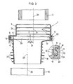
- FIG. 3 A further embodiment is illustrated in FIG. 3 in a representation analogous to FIG. 1.
- the expediently made of plastic pipe connection 1 has an approximately cylindrical pipe sleeve 3 which can be pushed onto the outlet pipe 2 of the toilet bowl and which is provided on the inside with an arc-shaped and elastically deformable annular sealing lip 4 which is directed against the outlet pipe 2 of the toilet bowl is.
- annular flange 6 which extends outward from the pipe sleeve, is provided on the pipe sleeve and is integrally formed with the pipe sleeve.
- the axis 7 of the flange 6 is arranged eccentrically to the axis 8 of the pipe sleeve by the dimension e.
- a vertically downwardly extending annular plug-in projection 9 is provided, the lower end 10 of which is widened in a bead shape.
- This plug-in projection protrudes into a groove 13 formed by U-shaped walls 11, 12 of a flange 17 arranged at the upper end 14 of a slightly conical pipe section 15 which can be inserted into the drain line 16 of a domestic sewer system.
- the groove 13 is on the input side of a bead 18 limited, whereby the U-shaped walls 11, 12 form a snap connection with the plug-in projection 9.
- Both the plug-in projection 9 and the groove 13 are designed in the form of a ring, so that the pipe sleeve 3 can be rotated relative to the pipe section 15.
- a rubber sealing cord 19 is inserted, so that the swivel joint 20 formed by the plug-in projection 9 and the groove 13 (or the walls 11, 12) is adequately sealed.
- the flange 17 of the pipe section 15 and the groove 13 are also arranged eccentrically with their axis 21 with respect to the axis 22 of the pipe section 15 by the dimension e, but are aligned with the axis 7.
- the pipe section 15 has radially extending sealing lips 23 arranged on the outside in a tiered manner, which effect a tightness of the pipe section 15 with respect to the drain line 16 of the domestic sewage system.
- 3 knobs 24 are arranged on the outside of the pipe sleeve.
- the distance of the axis 8 of the pipe sleeve 3 from the axis 22 of the pipe section 15 and thus the distance of the axis 25 of the outlet connector 2 of the toilet bowl and the axis 26 of the drain line 16 can be changed from zero to a maximum of 2e change, which makes it possible to set the toilet bowl within the range from zero to double eccentricity e regardless of the position of the drain line.
- This is elastically deformable and arranged on the lower, bead-like end 10 of the plug-in projection 9. It extends radially outwards and comes into contact with the inner wall 28 of the groove 13 in the assembled state of the pipe connection, whereby the tightness of the swivel joint 20 is ensured.
- a support web 29 extending in the axial direction is formed on the flange 6 of the pipe sleeve 3 and extends in the direction of the axis 25 to the opposite flange 17 of the pipe section 15.
- This support web 29 is provided in the region of the flange 6 on which it has a greater radial extension; it thus extends in the circumferential direction of the flange over about 180 ° and serves to avoid deformation of the flanges 6 and 17 when assembling the pipe connection or its installation, so that the exact fit of the pipe connection on the outlet pipe 2 of the toilet bowl and on the Drain pipe 16 of the house sewer system is guaranteed after installation.
Landscapes
- Health & Medical Sciences (AREA)
- Life Sciences & Earth Sciences (AREA)
- Engineering & Computer Science (AREA)
- Hydrology & Water Resources (AREA)
- Public Health (AREA)
- Water Supply & Treatment (AREA)
- Sanitary Device For Flush Toilet (AREA)
Abstract
Description
- Die Erfindung betrifft einen Rohranschluß zur Verbindung eines Abgangstutzens einer WC-Schale mit einer Ablaufleitung, mit einer auf den Abgangstutzen der WC-Schale aufschiebbaren Rohrmuffe und einem in die Ablaufleitung einsetzbaren Rohrstück. Eine Rohrverbindung dieser Art ist beispielsweise aus der AT-B -348.450 bekannt.
- Beim Installieren einer WC-Schale kann es zu Schwierigkeiten kommen, wenn der Abgangstutzen der WC-Schale mit der Ablaufleitung der Hauskanalisation nicht fluchtet. Insbesondere beim Austausch von alten WC-Schalen gegen neue stimmen oftmals die Installationsmaße -nämlich der Wandabstand zur Mitte der Ablaufleitung -nicht mehr mit den korrespondierenden Maßen der handelsüblichen WC-Schalen überein, wodurch eine neue WC-Schale nur unter Schwierigkeiten gesetzt werden kann.
- Es ist bekannt, zur Verbindung der WC-Schale mit der Ablaufleitung geknickte Rohranschlüsse zu verwenden, was jedoch eine aufwendige Lagerhaltung erfordert, da das Maß des Achsabstandes der Achse des Abgangstutzens der WC-Schale und der Ablaufleitung stark variieren kann. Eine besondere Problematik ergibt sich bei sogenannten "Einstückklosetts", bei denen der Spülkasten mit der WC-Schale eine Einheit bildet. Bei solchen "Einstückklosetts" ist nämlich die Lage der WC-Schale vom Anliegen des Spülkastens an der Wand abhängig.
- Die Erfindung bezweckt die Vermeidung dieser Schwierigkeiten und stellt sich die Aufgabe, einen Rohranschluß der eingangs beschriebenen Art zu - schaffen, mit dem die WC-Schale genau auf den gewünschten Platz setzbar ist, u.zw. unabhängig von der Lage der Ablaufleitung der Hauskanalisation.
- Diese Aufgabe wird erfindungsgemäß dadurch gelöst, daß die Rohrmuffe gegenüber dem Rohrstück mittels eines sowohl gegenüber der Rohrmuffe als auch gegenüber dem Rohrstück exzentrischen Drehgelenkes verdrehbar ist.
- Zwecks leichten Zusammenbaus des Rohranschlusses ist vorteilhaft das Drehgelenk als das Rohrstück mit der Rohrmuffe verbindende Schnappverbindung ausgebildet.
- Eine bevorzugte Ausführungsform ist dadurch gekennzeichnet, daß das Drehgelenk von einem kreisringförmigen Steckansatz, der am Rohrstück oder der Rohrmuffe angeordnet ist, und einer von U-förmig gestalteten Wänden gebildeten, kreisringförmigen und den Steckansatz aufnehmenden Rille, die am Rohr-Gegenstück angeordnet ist, gebildet ist, wobei vorteilhaft am Grund der Rille eine Dichtschnur eingelegt ist.
- Um den Zusammenbau des Rohranschlusses zu vereinfachen, ist zweckmäßig der Steckansatz integral mit einer elastisch verformbaren, an der Innenwand der Rille anliegenden Dichtlippe versehen, wodurch man sich die Dichtschnur erspart.
- Eine einfach herzustellende Ausführungsform ist dadurch gekennzeichnet, daß die Rohrmuffe an ihrem unteren Ende und das Rohrstück an seinem oberen Ende jeweils einstückig in einen exzentrischen Flansch übergehen, wobei jeder der Flansche mit einem Teil des Drehgelenkes einstückig ausgebildet ist.
- Um beim Zusammenbau bzw. Einbau des Rohranschlusses Verformungen an demselben zu vermeiden, ist vorteilhaft an einem der Flansche, vorzugsweise am Flansch der Rohrmuffe, ein bis zum gegenüberliegenden Flansch reichender Stützsteg vorgesehen.
- Um den Abstand der Achse der Rohrmuffe und dem Rohrstück zwischen Null und einem Maximalwert variieren lassen zu können, ist zweckmäßig die Achse des Drehgelenkes sowohl gegenüber der Achse der Rohrmuffe als auch gegenüber der Achse des Rohrstückes um dasselbe Maß exzentrisch versetzt angeordnet.
- Die Erfindung ist nachstehend anhand der Zeichnung an zwei Ausführungsbeispielen näher erläutert, wobei Fig. 1 einen Schnitt durch den Rohranschluß mit maximal eingestellter Exzentrizität und Fig. 2 einen Grundriß des Rohranschlusses gemäß einer ersten Ausführungsform zeigen. In Fig. 3 ist in zu Fig. 1 analoger Darstellung eine weitere Ausführungsform veranschaulicht.
- Der zweckmäßig aus Kunststoff gefertigte Rohranschluß 1 weist eine auf den Abgangstutzen 2 der WC-Schale aufschiebbare, etwa zylindrisch gestaltete Rohrmuffe 3 auf, die an der Innenseite mit gegen den Abgangstutzen 2 der WC-Schale gerichteten, bogenförmig gestalteten und elastisch verformbaren ringförmigen Dichtlippen 4 ausgestattet ist. Am unteren Ende 5 der Rohrmuffe 3 ist an der Rohrmuffe ein ringförmiger und sich von der Rohrmuffe nach außen erstreckender Flansch 6 vorgesehen, der mit der Rohrmuffe einstückig ausgebildet ist. Die Achse 7 des Flansches 6 ist gegenüber der Achse 8 der Rohrmuffe um das Maß e exzentrisch angeordnet.
- An der Unterseite des Flansches 6 ist ein sich vertikal nach unten erstreckender ringförmiger Steckansatz 9 vorgesehen, dessen unteres Ende 10 wulstförmig verbreitert ist. Dieser Steckansatz ragt in eine von U-förmig gestalteten Wänden 11, 12 gebildete Rille 13 eines am oberen Ende 14 eines leicht kegeligen Rohrstückes 15, das in die Ablaufleitung 16 einer Hauskanalisation einsetzbar ist, angeordneten Flansches 17. Die Rille 13 ist eingangsseitig von einem Wulst 18 begrenzt, wodurch die U-förmigen Wände 11, 12 mit dem Steckansatz 9 eine Schnappverbindung bilden. Sowohl der Steckansatz 9 als auch die Rille 13 sind kreisringförmig gestaltet, so daß die Rohrmuffe 3 gegenüber dem Rohrstück 15 verdrehbar ist.
- Am Grund der Rille 13 ist eine Gummidichtschnur 19 eingelegt, wodurch eine ausreichende Dichtheit des vom Steckansatz 9 und der Rille 13 - (bzw. den Wänden 11, 12) gebildeten Drehgelenkes 20 gegeben ist. Der Flansch 17 des Rohrstückes 15 und die Rille 13 sind mit ihrer Achse 21 gegenüber der Achse 22 des Rohrstückes 15 ebenfalls um das Maß e exzentrisch angeordnet, jedoch fluchtend zur Achse 7 ausgerichtet.
- Das Rohrstück 15 weist an seiner Außenseite etagenförmig angeordnete und sich radial erstreckende Dichtlippen 23 auf, die eine Dichtheit des Rohrstückes 15 gegenüber der Ablaufleitung 16 der Hauskanalisation bewirken. Um eine leichte Drehung der Rohrmuffe 3 gegenüber dem in die Ablaufleitung 16 eingesetzten Rohrstück 15 von Hand aus zu ermöglichen, sind an der Außenseite der Rohrmuffe 3 Griffnoppen 24 angeordnet.
- Durch Verdrehen der Rohrmuffe gegenüber dem Rohrstück läßt sich der Abstand der Achse 8 der Rohrmuffe 3 von der Achse 22 des Rohrstückes 15 und damit der Abstand der Achse 25 des Abgangstutzens 2 der WC-Schale und der Achse 26 der Ablaufleitung 16 von Null auf maximal 2e verändern, wodurch es möglich ist, die WC-Schale innerhalb des Bereiches von Null bis zur doppelten Exzentrizität e unabhängig von der Lage der Ablaufleitung zu setzen.
- Gemäß der in Fig. 3 dargestellten Ausführungsform ist anstelle der Gummidichtschnur 19 eine am Steckansatz 9 angeformte, d.h. mit ihm integral ausgebildete Dichtlippe 27 vorgesehen. Diese ist elastisch verformbar und am unteren, wulstartigen Ende 10 des Steckansatzes 9 angeordnet. Sie erstreckt sich radial nach außen und gelangt mit der Innenwand 28 der Rille 13 im zusammengebauten Zustand des Rohranschlusses in Kontakt, wodurch die Dichtheit des Drehgelenkes 20 gewährleistet ist.
- Am Flansch 6 der Rohrmuffe 3 ist ein sich in Achsrichtung erstreckender Stützsteg 29 angeformt, der sich in Richtung der Achse 25 bis zum gegenüberliegenden Flansch 17 des Rohrstückes 15 erstreckt. Dieser Stützsteg 29 ist in dem Bereich des Flansches 6 vorgesehen, an dem dieser eine größere radiale Erstreckung aufweist; er erstreckt sich somit in Umfangsrichtung des Flansches über etwa 180° und dient dazu, beim Zusammenbau des Rohranschlusses bzw. dessen Einbau Verformungen der Flansche 6 und 17 zu vermeiden, so daß der exakte Sitz des Rohranschlusses am Abgangstutzen 2 der WC-Schale und an der Ablaufleitung 16 der Hauskanalisation nach dem Einbau gewährleistet ist.
Claims (8)
Applications Claiming Priority (2)
| Application Number | Priority Date | Filing Date | Title |
|---|---|---|---|
| AT1556/85 | 1985-05-23 | ||
| AT155685A AT387416B (de) | 1985-05-23 | 1985-05-23 | Rohranschluss zur verbindung eines abgangstutzens einer wc-schale mit einer ablaufleitung |
Publications (3)
| Publication Number | Publication Date |
|---|---|
| EP0203055A2 true EP0203055A2 (de) | 1986-11-26 |
| EP0203055A3 EP0203055A3 (en) | 1987-06-03 |
| EP0203055B1 EP0203055B1 (de) | 1989-10-11 |
Family
ID=3515946
Family Applications (1)
| Application Number | Title | Priority Date | Filing Date |
|---|---|---|---|
| EP19860890117 Expired EP0203055B1 (de) | 1985-05-23 | 1986-04-28 | Rohranschluss zur Verbindung eines Abgangstutzens einer WC-Schale mit einer Ablaufleitung |
Country Status (3)
| Country | Link |
|---|---|
| EP (1) | EP0203055B1 (de) |
| AT (1) | AT387416B (de) |
| DE (1) | DE3666254D1 (de) |
Cited By (5)
| Publication number | Priority date | Publication date | Assignee | Title |
|---|---|---|---|---|
| FR2852038A1 (fr) * | 2003-03-07 | 2004-09-10 | Wirquin Plastiques Sa | Dispositif de siphon a sortie orientable pour une installation sanitaire |
| EP2816260A4 (de) * | 2012-02-16 | 2015-03-04 | Fominaya Sa | Kupplungsgelenk für toiletten |
| CN110644583A (zh) * | 2019-09-30 | 2020-01-03 | 陈林汝 | 一种可调节距离连接器 |
| CN116085554A (zh) * | 2023-01-16 | 2023-05-09 | 江门市科蓝环保设备有限公司 | 一种法兰补偿装置及管道系统 |
| WO2025241321A1 (zh) * | 2024-05-22 | 2025-11-27 | 厦门融技精密科技有限公司 | 一种可调排污连接管 |
Families Citing this family (2)
| Publication number | Priority date | Publication date | Assignee | Title |
|---|---|---|---|---|
| AT389669B (de) * | 1988-03-21 | 1990-01-10 | Hutterer & Lechner Kg | Spritzgussmaschine zum herstellen eines rohranschlusses aus kunststoff |
| AT401097B (de) * | 1994-02-09 | 1996-06-25 | Hutterer & Lechner Kg | Dichtung zum flüssigkeitsdichten verbinden zweier rohre |
Family Cites Families (5)
| Publication number | Priority date | Publication date | Assignee | Title |
|---|---|---|---|---|
| FR2235327A1 (en) * | 1973-06-29 | 1975-01-24 | Pont A Mousson | Expansion joint for telescoping plastic pipes - has U-section sealing ring pressed over outer tube end and outer ring |
| NL162451C (nl) * | 1976-09-24 | 1980-05-16 | Kleinhof Bv F | Closetsok. |
| GB2012902B (en) * | 1977-11-09 | 1982-04-28 | Phetco Ltd | Connectors for connecting wc pans to soil pipes |
| DE3011228A1 (de) * | 1980-03-22 | 1981-10-01 | Naamloze Vennootschap Koninklijke Sphinx, Maastricht | Montageelement |
| BE901076A (nl) * | 1984-11-19 | 1985-03-15 | Dejaeghere Julien | Aansluitkast voor het op een schoorsteen of afvoerkanaal aansluiten van kachels, ventilatieapparaten en andere. |
-
1985
- 1985-05-23 AT AT155685A patent/AT387416B/de not_active IP Right Cessation
-
1986
- 1986-04-28 DE DE8686890117T patent/DE3666254D1/de not_active Expired
- 1986-04-28 EP EP19860890117 patent/EP0203055B1/de not_active Expired
Cited By (5)
| Publication number | Priority date | Publication date | Assignee | Title |
|---|---|---|---|---|
| FR2852038A1 (fr) * | 2003-03-07 | 2004-09-10 | Wirquin Plastiques Sa | Dispositif de siphon a sortie orientable pour une installation sanitaire |
| EP2816260A4 (de) * | 2012-02-16 | 2015-03-04 | Fominaya Sa | Kupplungsgelenk für toiletten |
| CN110644583A (zh) * | 2019-09-30 | 2020-01-03 | 陈林汝 | 一种可调节距离连接器 |
| CN116085554A (zh) * | 2023-01-16 | 2023-05-09 | 江门市科蓝环保设备有限公司 | 一种法兰补偿装置及管道系统 |
| WO2025241321A1 (zh) * | 2024-05-22 | 2025-11-27 | 厦门融技精密科技有限公司 | 一种可调排污连接管 |
Also Published As
| Publication number | Publication date |
|---|---|
| EP0203055A3 (en) | 1987-06-03 |
| ATA155685A (de) | 1988-06-15 |
| EP0203055B1 (de) | 1989-10-11 |
| DE3666254D1 (en) | 1989-11-16 |
| AT387416B (de) | 1989-01-25 |
Similar Documents
| Publication | Publication Date | Title |
|---|---|---|
| EP0913534B1 (de) | Spül- und Kontroll-Schacht für Flüssigkeitsleitungen und Schacht-Abschnitt hierfür | |
| EP3885498B1 (de) | Sanitäre wandeinbau-anschlussboxeinheit mit elektrischer leitungsdurchführung | |
| DE19648587B4 (de) | Unterputz-Einbaukasten für Sanitärarmaturen | |
| EP0203055B1 (de) | Rohranschluss zur Verbindung eines Abgangstutzens einer WC-Schale mit einer Ablaufleitung | |
| DE69408863T2 (de) | Einsteigeschacht | |
| DE10201345A1 (de) | Ablaufvorrichtung für den Einbau in den Boden eines Raumes | |
| EP0794375A2 (de) | Dichtungsmuffe für Rohre | |
| DE60209694T2 (de) | Einlassystem für einen zentralen Staubsauger | |
| EP0903444B1 (de) | Urinanlage aus Keramik, Glas oder Metall | |
| DE4243737C1 (de) | Dichtungseinrichtung zur Abdichtung eines Doppelrohres, welches ein inneres Kernrohr und ein sich hierzu parallel erstreckendes äußeres Wellrohr umfaßt, gegen die Wand eines Montagekastens für eine Sanitärarmatur | |
| EP0074034B1 (de) | Einbauhilfe für ein Einsatzteil in einen Abwasser-Sammel-behälter | |
| EP0333657B1 (de) | Vorrichtung zum Verbinden eines Ablaufrohres mit einem Spülkasten | |
| EP0503258B1 (de) | Verbindungsanordnung einer Rohrleitung | |
| EP0792401B1 (de) | Unterputzsifon | |
| EP0354177B2 (de) | Anschlussarmatur für flexible Rohrleitungen | |
| DE19634149C2 (de) | Röhrensifon mit Steckverbindung | |
| EP0499886B1 (de) | Sanitäre Wandarmatur | |
| EP0893866B1 (de) | Unterputzinstallationsdose | |
| AT401097B (de) | Dichtung zum flüssigkeitsdichten verbinden zweier rohre | |
| EP0581734A1 (de) | Abwasserleitungsmodul | |
| EP0445416B1 (de) | Klosett-Anschlussbogen | |
| WO2000058574A1 (de) | Trichter, insbesondere aus kunststoff, für strassenabläufe, und verfahren zu dessen herstellung | |
| AT401402B (de) | Unterputzsifon | |
| EP0557750B1 (de) | Ablaufarmatur einer wandhängenden Toilette | |
| DE2737043A1 (de) | Anpassungsteil fuer einen ablaufstutzen |
Legal Events
| Date | Code | Title | Description |
|---|---|---|---|
| PUAI | Public reference made under article 153(3) epc to a published international application that has entered the european phase |
Free format text: ORIGINAL CODE: 0009012 |
|
| AK | Designated contracting states |
Kind code of ref document: A2 Designated state(s): BE CH DE FR GB IT LI LU NL SE |
|
| PUAL | Search report despatched |
Free format text: ORIGINAL CODE: 0009013 |
|
| AK | Designated contracting states |
Kind code of ref document: A3 Designated state(s): BE CH DE FR GB IT LI LU NL SE |
|
| 17P | Request for examination filed |
Effective date: 19871123 |
|
| 17Q | First examination report despatched |
Effective date: 19881014 |
|
| GRAA | (expected) grant |
Free format text: ORIGINAL CODE: 0009210 |
|
| AK | Designated contracting states |
Kind code of ref document: B1 Designated state(s): BE CH DE FR GB IT LI LU NL SE |
|
| PG25 | Lapsed in a contracting state [announced via postgrant information from national office to epo] |
Ref country code: SE Effective date: 19891011 Ref country code: BE Effective date: 19891011 |
|
| REF | Corresponds to: |
Ref document number: 3666254 Country of ref document: DE Date of ref document: 19891116 |
|
| ET | Fr: translation filed | ||
| ITF | It: translation for a ep patent filed | ||
| GBT | Gb: translation of ep patent filed (gb section 77(6)(a)/1977) | ||
| PLBE | No opposition filed within time limit |
Free format text: ORIGINAL CODE: 0009261 |
|
| STAA | Information on the status of an ep patent application or granted ep patent |
Free format text: STATUS: NO OPPOSITION FILED WITHIN TIME LIMIT |
|
| 26N | No opposition filed | ||
| ITTA | It: last paid annual fee | ||
| EPTA | Lu: last paid annual fee | ||
| PGFP | Annual fee paid to national office [announced via postgrant information from national office to epo] |
Ref country code: LU Payment date: 19950401 Year of fee payment: 10 |
|
| PGFP | Annual fee paid to national office [announced via postgrant information from national office to epo] |
Ref country code: CH Payment date: 19950428 Year of fee payment: 10 |
|
| PG25 | Lapsed in a contracting state [announced via postgrant information from national office to epo] |
Ref country code: LU Free format text: LAPSE BECAUSE OF NON-PAYMENT OF DUE FEES Effective date: 19960428 |
|
| PG25 | Lapsed in a contracting state [announced via postgrant information from national office to epo] |
Ref country code: LI Effective date: 19960430 Ref country code: CH Effective date: 19960430 |
|
| REG | Reference to a national code |
Ref country code: CH Ref legal event code: PL |
|
| PGFP | Annual fee paid to national office [announced via postgrant information from national office to epo] |
Ref country code: NL Payment date: 20000428 Year of fee payment: 15 |
|
| PGFP | Annual fee paid to national office [announced via postgrant information from national office to epo] |
Ref country code: FR Payment date: 20010314 Year of fee payment: 16 |
|
| PGFP | Annual fee paid to national office [announced via postgrant information from national office to epo] |
Ref country code: GB Payment date: 20010423 Year of fee payment: 16 Ref country code: DE Payment date: 20010423 Year of fee payment: 16 |
|
| PG25 | Lapsed in a contracting state [announced via postgrant information from national office to epo] |
Ref country code: NL Free format text: LAPSE BECAUSE OF NON-PAYMENT OF DUE FEES Effective date: 20011101 |
|
| REG | Reference to a national code |
Ref country code: GB Ref legal event code: IF02 |
|
| NLV4 | Nl: lapsed or anulled due to non-payment of the annual fee |
Effective date: 20011101 |
|
| PG25 | Lapsed in a contracting state [announced via postgrant information from national office to epo] |
Ref country code: GB Free format text: LAPSE BECAUSE OF NON-PAYMENT OF DUE FEES Effective date: 20020428 |
|
| PG25 | Lapsed in a contracting state [announced via postgrant information from national office to epo] |
Ref country code: DE Free format text: LAPSE BECAUSE OF NON-PAYMENT OF DUE FEES Effective date: 20021101 |
|
| GBPC | Gb: european patent ceased through non-payment of renewal fee |
Effective date: 20020428 |
|
| PG25 | Lapsed in a contracting state [announced via postgrant information from national office to epo] |
Ref country code: FR Free format text: LAPSE BECAUSE OF NON-PAYMENT OF DUE FEES Effective date: 20021231 |
|
| REG | Reference to a national code |
Ref country code: FR Ref legal event code: ST |
|
| PG25 | Lapsed in a contracting state [announced via postgrant information from national office to epo] |
Ref country code: IT Free format text: LAPSE BECAUSE OF NON-PAYMENT OF DUE FEES;WARNING: LAPSES OF ITALIAN PATENTS WITH EFFECTIVE DATE BEFORE 2007 MAY HAVE OCCURRED AT ANY TIME BEFORE 2007. THE CORRECT EFFECTIVE DATE MAY BE DIFFERENT FROM THE ONE RECORDED. Effective date: 20050428 |