EP0203252A2 - Isoliergasgefüllte, gekapselte Schaltanlage mit einer Anzeigevorrichtung für die Isoliergasdichte innerhalb der Schaltanlage - Google Patents
Isoliergasgefüllte, gekapselte Schaltanlage mit einer Anzeigevorrichtung für die Isoliergasdichte innerhalb der Schaltanlage Download PDFInfo
- Publication number
- EP0203252A2 EP0203252A2 EP86100625A EP86100625A EP0203252A2 EP 0203252 A2 EP0203252 A2 EP 0203252A2 EP 86100625 A EP86100625 A EP 86100625A EP 86100625 A EP86100625 A EP 86100625A EP 0203252 A2 EP0203252 A2 EP 0203252A2
- Authority
- EP
- European Patent Office
- Prior art keywords
- switchgear
- switchgear according
- insulating gas
- display device
- counter electrode
- Prior art date
- Legal status (The legal status is an assumption and is not a legal conclusion. Google has not performed a legal analysis and makes no representation as to the accuracy of the status listed.)
- Granted
Links
Images
Classifications
-
- H—ELECTRICITY
- H02—GENERATION; CONVERSION OR DISTRIBUTION OF ELECTRIC POWER
- H02B—BOARDS, SUBSTATIONS OR SWITCHING ARRANGEMENTS FOR THE SUPPLY OR DISTRIBUTION OF ELECTRIC POWER
- H02B13/00—Arrangement of switchgear in which switches are enclosed in, or structurally associated with, a casing, e.g. cubicle
- H02B13/02—Arrangement of switchgear in which switches are enclosed in, or structurally associated with, a casing, e.g. cubicle with metal casing
- H02B13/035—Gas-insulated switchgear
- H02B13/065—Means for detecting or reacting to mechanical or electrical defects
-
- H—ELECTRICITY
- H02—GENERATION; CONVERSION OR DISTRIBUTION OF ELECTRIC POWER
- H02B—BOARDS, SUBSTATIONS OR SWITCHING ARRANGEMENTS FOR THE SUPPLY OR DISTRIBUTION OF ELECTRIC POWER
- H02B13/00—Arrangement of switchgear in which switches are enclosed in, or structurally associated with, a casing, e.g. cubicle
- H02B13/02—Arrangement of switchgear in which switches are enclosed in, or structurally associated with, a casing, e.g. cubicle with metal casing
- H02B13/035—Gas-insulated switchgear
- H02B13/065—Means for detecting or reacting to mechanical or electrical defects
- H02B13/0655—Means for detecting or reacting to mechanical or electrical defects through monitoring changes of gas properties
Definitions
- the invention relates to an encapsulated switchgear filled with insulating gas according to the preamble of claim 1.
- the display device for the insulation gas density within the system consists of a hollow display element which is filled with a gas which is lighter than the insulation gas. A change in the position of the display element is caused by a reduction in the insulating gas density. Proportional to the decreasing insulating gas density, a spring-elastic counterforce acts on the display element. With the help of this device it is possible to read off the prevailing insulating gas density.
- a simple, space-saving test device for determining the insulating gas density is also known, in which the dielectric strength of the gas in the switchgear is tested with the aid of a commercially available spark plug (DE-GM 78 26 451). As soon as the SF 6 insulating gas in the switchgear is reduced, the dielectric strength is reduced.
- the spark plug is used in the switchgear in such a way that its center and earth electrodes protrude into the insulating gas filling, while the connection electrode of the spark plug is in a location accessible to the control personnel protrudes from the system encapsulation.
- a voltage must be applied artificially. As in the case described above, the control personnel must also convince themselves of the condition of the insulating gas on site.
- So-called density scales are also used in SF 6 switchgear, which indicate with a float that SF 6 gas is present.
- SF 6 is heavier than air and has correspondingly balanced display parts floating, so that the presence of SF 6 is thereby proven.
- these ads are very sensitive.
- the invention has for its object to provide a display device for a switchgear described above, which is able to report a reduction in the insulating gas within the switchgear and at the same time lock the drives of the switches.
- the advantages achieved by the invention are that the display device according to the invention of the switchgear described above signals a malfunction directly without carrying out measurements. This considerably simplifies the work of the control staff.
- the counterelectrode has a shape such that it works partially discharge-free in the case of SF 6 as an insulating gas, but generates a discharge current from the busbar to earth in a specific SF 6 -air mixture (claim 4).
- the trigger for a residual current circuit breaker has so much triggering force that it can easily actuate an optical or acoustic display (claims 6 + 7).
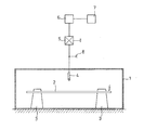
- FIG. 1 An embodiment of the invention is shown in a drawing and is explained in more detail in the folqenden.
- the figure shows an encapsulated switchgear filled with insulating gas with a display device for the insulating gas density.
- the switchgear consists of an encapsulated housing 1, which is filled with SF 6 as an insulating gas.
- a live busbar 2 rests on two supports 3 which are fastened to the housing base.
- a counter electrode 4 is attached at a certain distance above the busbar and is connected to a triggering device 5 located outside the switchgear.
- This triggering device is grounded on the one hand and connected to a display device 6 on the other hand.
- This display can be an optical or acoustic device.
- This display device is in turn connected to the lock 7 of the switch drives. Using a test test socket 8 between the counter electrode and the triggering device 5, the voltage occurring at the counter electrode can be checked.
- the mode of operation of the display device is such that, in the normal case (SF 6 between the counter electrode and busbar), no partial discharge current can flow, since the SF 6 functions as an insulating agent. If the SF 6 disappears and is replaced by air, a corresponding current will occur and operate the aforementioned display and / or lock.
Landscapes
- Engineering & Computer Science (AREA)
- Power Engineering (AREA)
- Driving Mechanisms And Operating Circuits Of Arc-Extinguishing High-Tension Switches (AREA)
- Gas-Insulated Switchgears (AREA)
Abstract
Description
- Die Erfindung betrifft eine isoliergasgefüllte, gekapselte Schaltanlage gemäß dem Oberbegriff des Anspruchs 1.
- Eine derartige Schaltanlage ist bereits bekannt (DE-OS 28 27 406). Die Anzeigevorrichtung für die Isoliergasdichte innerhalb der Anlage besteht aus einem hohlräumigen Anzeigeelement, das mit einem gegenüber dem Isoliergas leichteren Gas gefüllt ist. Durch eine Verringerung der Isoliergasdichte wird eine Lageänderung des Anzeigeelements hervorgerufen. Proportional zur abnehmenden Isoliergasdichte wirkt auf das Anzeigeelement eine federelastische Gegenkraft. Mit Hilfe dieser Einrichtung ist es möglich, diejeweils herrschende Isoliergasdichte abzulesen.
- Es ist ferner eine einfache, raumsparende Prüfeinrichtung zur Bestimmung der Isoliergasdichte bekannt, bei welcher die Prüfung der Durchschlagsfestigkeit des in der Schaltanlage befindlichen Gases mit Hilfe einer handelsüblichen Zündkerze vorgenommen wird (DE-GM 78 26 451). Sowie sich das SF6-Isoliergas in der Schaltanlage verringert, wird die Durchschlagsfestigkeit abgesenkt. Die Zündkerze ist hierbei in der Schaltanlage so eingesetzt, daß deren Mittel- und Masseelektrode in die Isoliergasfüllung hineinragt, während die Anschlußelektrode der Zündkerze an einem für das Kontrollpersonal zugänglichen Ort aus der Anlagenkapselung herausragt. Um die Anzeige über das Isoliergas zu erhalten, muß eine Spannung künstlich aufgegeben werden. Wie auch im zuvor geschilderten Fall muß auch hier das Kontrollpersonal sich vor Ort vom Zustand des Isoliergases überzeugen.
- Es ist allgemein üblich, bei Druckmessungen Manometer einzubauen, welche allerdings den Nachteil haben, daß der angezeigte Druck von den Außenverhältnissen abhängig ist. Hat die Anlage im Normalfall einen geringen Innendruck, wie dies bei SF6-Schaltanlagen mit Lasttrennschaltern für Mittelspannung zum großen Teil der Fall ist, so kann bei abgesenkten Temperaturen eine Null-Anzeige erscheinen, obgleich die Anlage noch absolut in Ordnung ist.
- Es sind bei SF6-Schaltanlagen auch sogenannte Dichte-Waagen im Einsatz, welche mit einem Schwimmer anzeigen, daß SF6-Gas vorhanden ist. Bekanntlich ist SF6 schwerer als Luft und läßt entsprechend ausgewogene Anzeigeteile schweben, so daß das Vorhandensein von SF6 hierdurch nachgewiesen ist. Allerdings sind diese Anzeigen sehr empfindlich.
- Zu erwähnen sind noch Feuchte-Anzeigen, die mit Feuchte-Indikatoren arbeiten und die dann ansprechen, wenn SF verlorengegangen und daher feuchte Luft in die Schaltanlage eingedrungen ist. Diese Anzeigen sind jedoch auch nicht zulässig, da das trockene SF6 möglicherweise in trockenen Klimaten durch trockene Luft ersetzt werden kann und daher die Anzeige später kommt als der gefährliche Betriebszustand eingetreten ist.
- Der Erfindung liegt die Aufgabe zugrunde, eine Anzeigevorrichtung für eine eingangs geschilderte Schaltanlage zu schaffen, die in der Lage ist, eine Verringerung des Isoliergases innerhalb der Schaltanlage zu melden und dabei gleichzeitig die Antriebe der Schalter zu sperren.
- Diese Aufgabe wird erfindungsgemäß durch die im Kennzeichen des Anspruchs 1 angegebenen Merkmale gelöst.
- Die mit der Erfindung erzielten Vorteile bestehen darin, daß die erfindungsgemäße Anzeigevorrichtung der zuvor geschilderten Schaltanlage einen Störungsfall ohne Durchführung von Messungen direkt signalisiert. Dies bedeutet eine erhebliche Vereinfachung der Arbeit des Kontrollpersonals.
- Zweckmäßige Aus- und Weiterbildungen des Gegenstandes nach Anspruch 1 sind den Unteransprüchen zu entnehmen.
- Hierbei erweist es sich als zweckmäßig, daß die Gegenelektrode eine derartige Formgebung aufweist, daß sie bei SF6 als Isoliergas teilentladungsfrei arbeitet, jedoch bei einem bestimmten SF6-Luftgemisch einen Entladungsstrom von der Sammelschiene gegen Erde erzeugt (Anspruch 4).
- Dies führt vorteilhafterweise zu einem Einsatz einer Auslöseeinrichtung, wie sie als Auslöser für einen Fehlerstrom-Schutzschalter bekannt ist (Anspruch 5).
- Der Auslöser für einen Fehlerstrom-Schutzschalter besitzt bekanntlich soviel Auslösekraft, daß er ohne weiteres eine Anzeige optischer oder akustischer Art betätigen kann (Ansprüche 6 + 7).
- Ein Ausführungsbeispiel der Erfindung ist in einer Zeichnung dargestellt und wird im Folqenden näher erläutert. Es zeigt die Figur eine isoliergasgefüllte, gekapselte Schaltanlage mit einer Anzeigevorrichtung für die Isoliergasdichte.
- Nach der Figur besteht die Schaltanlage aus einem gekapselten Gehäuse 1, das mit SF6 als Isoliergas gefüllt ist. Eine unter Spannung stehende Sammelschiene 2 ruht auf zwei Stützern 3, die auf dem Gehäuseboden befestigt sind. In einem bestimmten Abstand ist über der Sammelschiene eine Gegenelektrode 4 angebracht, die mit einer außerhalb der Schaltanlage befindlichen Auslöseeinrichtung 5 verbunden ist. Diese Auslöseeinrichtung ist einerseits geerdet und andererseits an eine Anzeigevorrichtung 6 angeschlossen. Bei dieser Anzeige kann es sich um eine optische oder akustische Einrichtung handeln. Diese Anzeigevorrichtung steht wiederum mit der Verriegelung 7 der Schalterantriebe in Verbindung. Mittels einer Prüf-Testbuchse 8 zwischen der Gegenelektrode und der Auslöseeinrichtung 5 läßt sich die an der Gegenelektrode auftretende Spannung überprüfen.
- Die Wirkungsweise der Anzeigevorrichtung ist dergestalt, daß im Normalfall (SF6 zwischen Gegenelektrode und Sammelschiene) kein Teilentladungsstrom fließen kann, da das SF6 eine Funktion als Isoliermittel ausübt. Verschwindet das SF6 und wird durch Luft ersetzt, so wird ein entsprechender Strom auftreten und die zuvor erwähnte Anzeige und/oder Verriegelung betätigen.
Claims (9)
Priority Applications (1)
| Application Number | Priority Date | Filing Date | Title |
|---|---|---|---|
| AT86100625T ATE53714T1 (de) | 1985-05-25 | 1986-01-18 | Isoliergasgefuellte, gekapselte schaltanlage mit einer anzeigevorrichtung fuer die isoliergasdichte innerhalb der schaltanlage. |
Applications Claiming Priority (2)
| Application Number | Priority Date | Filing Date | Title |
|---|---|---|---|
| DE3518932 | 1985-05-25 | ||
| DE19853518932 DE3518932A1 (de) | 1985-05-25 | 1985-05-25 | Isoliergasgefuellte, gekapselte schaltanlage mit einer anzeigevorrichtung fuer die isoliergasdichte innerhalb der schaltanlage |
Publications (3)
| Publication Number | Publication Date |
|---|---|
| EP0203252A2 true EP0203252A2 (de) | 1986-12-03 |
| EP0203252A3 EP0203252A3 (en) | 1987-12-02 |
| EP0203252B1 EP0203252B1 (de) | 1990-06-13 |
Family
ID=6271691
Family Applications (1)
| Application Number | Title | Priority Date | Filing Date |
|---|---|---|---|
| EP86100625A Expired - Lifetime EP0203252B1 (de) | 1985-05-25 | 1986-01-18 | Isoliergasgefüllte, gekapselte Schaltanlage mit einer Anzeigevorrichtung für die Isoliergasdichte innerhalb der Schaltanlage |
Country Status (4)
| Country | Link |
|---|---|
| EP (1) | EP0203252B1 (de) |
| JP (1) | JPS61273109A (de) |
| AT (1) | ATE53714T1 (de) |
| DE (2) | DE3518932A1 (de) |
Cited By (3)
| Publication number | Priority date | Publication date | Assignee | Title |
|---|---|---|---|---|
| EP0476502A3 (de) * | 1990-09-17 | 1992-12-30 | Hitachi, Ltd. | Gasisoliertes elektrisches Gerät |
| EP1054493A1 (de) * | 1999-05-21 | 2000-11-22 | Mitsubishi Denki Kabushiki Kaisha | Gasisolierte Schaltanlage |
| WO2014037031A1 (en) * | 2012-09-04 | 2014-03-13 | Abb Technology Ag | Insulation fluid filling method and filling apparatus |
Families Citing this family (1)
| Publication number | Priority date | Publication date | Assignee | Title |
|---|---|---|---|---|
| DE102017202986A1 (de) * | 2017-02-23 | 2018-08-23 | Siemens Aktiengesellschaft | Elektrisches Mittel- oder Hochspannungsgerät sowie Verfahren zum Betreiben eines elektrischen Mittel- oder Hochspannungsgeräts |
Family Cites Families (3)
| Publication number | Priority date | Publication date | Assignee | Title |
|---|---|---|---|---|
| DE2341073B2 (de) * | 1973-08-10 | 1980-01-10 | Siemens Ag, 1000 Berlin Und 8000 Muenchen | Meßeinrichtung für die Spannung in einer gekapselten Hochspannungsschaltanlage |
| JPS6016163B2 (ja) * | 1978-02-03 | 1985-04-24 | 株式会社日立製作所 | ガス絶縁電気機器およびその部分放電検出方法 |
| DE3327917A1 (de) * | 1983-07-29 | 1985-02-07 | Siemens AG, 1000 Berlin und 8000 München | Messvorrichtung zur feststellung von teilentladungen innerhalb metallgekapselter, druckgasisolierter hochspannungsschaltanlagen |
-
1985
- 1985-05-25 DE DE19853518932 patent/DE3518932A1/de not_active Withdrawn
-
1986
- 1986-01-18 AT AT86100625T patent/ATE53714T1/de not_active IP Right Cessation
- 1986-01-18 DE DE8686100625T patent/DE3672037D1/de not_active Expired - Fee Related
- 1986-01-18 EP EP86100625A patent/EP0203252B1/de not_active Expired - Lifetime
- 1986-05-26 JP JP61119403A patent/JPS61273109A/ja active Pending
Cited By (4)
| Publication number | Priority date | Publication date | Assignee | Title |
|---|---|---|---|---|
| EP0476502A3 (de) * | 1990-09-17 | 1992-12-30 | Hitachi, Ltd. | Gasisoliertes elektrisches Gerät |
| US6063997A (en) * | 1990-09-17 | 2000-05-16 | Hitachi, Ltd. | Gas insulated electric apparatus |
| EP1054493A1 (de) * | 1999-05-21 | 2000-11-22 | Mitsubishi Denki Kabushiki Kaisha | Gasisolierte Schaltanlage |
| WO2014037031A1 (en) * | 2012-09-04 | 2014-03-13 | Abb Technology Ag | Insulation fluid filling method and filling apparatus |
Also Published As
| Publication number | Publication date |
|---|---|
| JPS61273109A (ja) | 1986-12-03 |
| DE3672037D1 (de) | 1990-07-19 |
| DE3518932A1 (de) | 1986-11-27 |
| ATE53714T1 (de) | 1990-06-15 |
| EP0203252A3 (en) | 1987-12-02 |
| EP0203252B1 (de) | 1990-06-13 |
Similar Documents
| Publication | Publication Date | Title |
|---|---|---|
| DE102019126134B4 (de) | Gasdichtemesser | |
| DE2548173B2 (de) | Einrichtung zur Erfassung eines Hochspannungspotentials in metallgekapselten Hochspannungsschaltanlagen und -geräten | |
| EP0203252A2 (de) | Isoliergasgefüllte, gekapselte Schaltanlage mit einer Anzeigevorrichtung für die Isoliergasdichte innerhalb der Schaltanlage | |
| DE4136639C2 (de) | Vorrichtung zur elektrischen Ermittlung nicht gelöster Gase in mit Flüssigkeit gefüllten Hochspannungsanlagen und Geräten als Grundlage zur Fehlererkennung und Überwachung dieser Anlagen und Geräte | |
| DE3423444A1 (de) | Geraet fuer die begrenzung von oder den schutz vor auftretenden ueberspannungen mit einer hierin enthaltenen vorrichtung zum feststellen und anzeigen des auf alterung oder auf einen katastrophenfall zurueckgehenden lebensendes des geraetes | |
| EP0464021A1 (de) | Messeinrichtung mit einer hilfselektrode für eine gasisolierte gekapselte hochspannungsanlage. | |
| DE2155398C3 (de) | Anordnung zur Erkennung des freigeschalteten Zustandes eines abtrennbaren Anlagenteiles einer gekapselten isoliergasgefüllten Hochspannungsschaltanlage | |
| EP0612411B1 (de) | Hochspannungsmesseinrichtung | |
| DE2447240C2 (de) | Einrichtung zur Erfassung und Signalisierung von in einem geschlossenen Behälter auftretendem Licht | |
| EP0104354B1 (de) | Kapazitive Betriebsanzeige für Mittelspannungs-Garnituren | |
| DE3623424C2 (de) | Verfahren zum Abschalten einer ein- oder mehrphasigen elektrischen Schaltanlage und Einrichtung zur Abschaltung | |
| EP0309385B1 (de) | Elektrischer Druckgas-Leistungsschalter, insbesondere SF6-Hochspannungs-Leistungsschalter | |
| EP0621611B1 (de) | Stützisolator | |
| DE3421829A1 (de) | Messverfahren zur ueberpruefung von schutzmassnahmen in elektrischen anlagen und messgeraet zur durchfuehrung des verfahrens | |
| DE3539421A1 (de) | Schaltungsanordnung zum schutz gegen ueberspannungen | |
| DE3910696A1 (de) | Verfahren zum ueberwachen des drucks in einer druckgasgefuellten kammer sowie eine vorrichtung zur durchfuehrung des verfahrens | |
| EP1439548A1 (de) | Einbaumodul für Hochspannungsanlage | |
| DE2758800A1 (de) | Vorrichtung zum erfassen eines hochspannungspotentials in metallgekapselten, druckgasisolierten hochspannungsschaltanlagen | |
| DE2703421A1 (de) | Dichtemesser fuer gase | |
| DE1271602B (de) | Elektrische UEberwachungseinrichtung | |
| DE1808537A1 (de) | Spannungssucher fuer Hochspannungs-Freiluftanlagen | |
| DE19505696C1 (de) | Überwachungseinrichtung | |
| DE29804939U1 (de) | Wasserzähler mit Rollenzählwerk und Kontakteinrichtung | |
| EP0157940A2 (de) | Kondensatoranlage für die Anwendung im schlagwettergefährdeten Bergbau | |
| DE9202323U1 (de) | Schwimmschalter |
Legal Events
| Date | Code | Title | Description |
|---|---|---|---|
| PUAI | Public reference made under article 153(3) epc to a published international application that has entered the european phase |
Free format text: ORIGINAL CODE: 0009012 |
|
| AK | Designated contracting states |
Kind code of ref document: A2 Designated state(s): AT BE CH DE FR GB IT LI NL SE |
|
| PUAL | Search report despatched |
Free format text: ORIGINAL CODE: 0009013 |
|
| AK | Designated contracting states |
Kind code of ref document: A3 Designated state(s): AT BE CH DE FR GB IT LI NL SE |
|
| 17P | Request for examination filed |
Effective date: 19871029 |
|
| RAP1 | Party data changed (applicant data changed or rights of an application transferred) |
Owner name: FELTEN & GUILLEAUME ENERGIETECHNIK AG |
|
| 17Q | First examination report despatched |
Effective date: 19890714 |
|
| GRAA | (expected) grant |
Free format text: ORIGINAL CODE: 0009210 |
|
| AK | Designated contracting states |
Kind code of ref document: B1 Designated state(s): AT BE CH DE FR GB IT LI NL SE |
|
| REF | Corresponds to: |
Ref document number: 53714 Country of ref document: AT Date of ref document: 19900615 Kind code of ref document: T |
|
| ITF | It: translation for a ep patent filed | ||
| GBT | Gb: translation of ep patent filed (gb section 77(6)(a)/1977) | ||
| REF | Corresponds to: |
Ref document number: 3672037 Country of ref document: DE Date of ref document: 19900719 |
|
| ET | Fr: translation filed | ||
| PGFP | Annual fee paid to national office [announced via postgrant information from national office to epo] |
Ref country code: BE Payment date: 19901010 Year of fee payment: 6 |
|
| PGFP | Annual fee paid to national office [announced via postgrant information from national office to epo] |
Ref country code: AT Payment date: 19901127 Year of fee payment: 6 |
|
| PGFP | Annual fee paid to national office [announced via postgrant information from national office to epo] |
Ref country code: SE Payment date: 19901218 Year of fee payment: 6 |
|
| PGFP | Annual fee paid to national office [announced via postgrant information from national office to epo] |
Ref country code: GB Payment date: 19910104 Year of fee payment: 6 |
|
| PGFP | Annual fee paid to national office [announced via postgrant information from national office to epo] |
Ref country code: CH Payment date: 19910111 Year of fee payment: 6 |
|
| PGFP | Annual fee paid to national office [announced via postgrant information from national office to epo] |
Ref country code: FR Payment date: 19910123 Year of fee payment: 6 |
|
| ITTA | It: last paid annual fee | ||
| PGFP | Annual fee paid to national office [announced via postgrant information from national office to epo] |
Ref country code: NL Payment date: 19910131 Year of fee payment: 6 |
|
| PGFP | Annual fee paid to national office [announced via postgrant information from national office to epo] |
Ref country code: DE Payment date: 19910207 Year of fee payment: 6 |
|
| PLBE | No opposition filed within time limit |
Free format text: ORIGINAL CODE: 0009261 |
|
| STAA | Information on the status of an ep patent application or granted ep patent |
Free format text: STATUS: NO OPPOSITION FILED WITHIN TIME LIMIT |
|
| 26N | No opposition filed | ||
| PG25 | Lapsed in a contracting state [announced via postgrant information from national office to epo] |
Ref country code: GB Effective date: 19920118 Ref country code: AT Effective date: 19920118 |
|
| PG25 | Lapsed in a contracting state [announced via postgrant information from national office to epo] |
Ref country code: SE Effective date: 19920119 |
|
| PG25 | Lapsed in a contracting state [announced via postgrant information from national office to epo] |
Ref country code: LI Effective date: 19920131 Ref country code: CH Effective date: 19920131 Ref country code: BE Effective date: 19920131 |
|
| BERE | Be: lapsed |
Owner name: FELTEN & GUILLEAUME ENERGIETECHNIK A.G. Effective date: 19920131 |
|
| PG25 | Lapsed in a contracting state [announced via postgrant information from national office to epo] |
Ref country code: NL Effective date: 19920801 |
|
| NLV4 | Nl: lapsed or anulled due to non-payment of the annual fee | ||
| REG | Reference to a national code |
Ref country code: GB Ref legal event code: PCNP |
|
| PG25 | Lapsed in a contracting state [announced via postgrant information from national office to epo] |
Ref country code: FR Effective date: 19920930 |
|
| REG | Reference to a national code |
Ref country code: CH Ref legal event code: PL |
|
| PG25 | Lapsed in a contracting state [announced via postgrant information from national office to epo] |
Ref country code: DE Effective date: 19921001 |
|
| REG | Reference to a national code |
Ref country code: FR Ref legal event code: ST |
|
| EUG | Se: european patent has lapsed |
Ref document number: 86100625.2 Effective date: 19920806 |
|
| PG25 | Lapsed in a contracting state [announced via postgrant information from national office to epo] |
Ref country code: IT Free format text: LAPSE BECAUSE OF NON-PAYMENT OF DUE FEES;WARNING: LAPSES OF ITALIAN PATENTS WITH EFFECTIVE DATE BEFORE 2007 MAY HAVE OCCURRED AT ANY TIME BEFORE 2007. THE CORRECT EFFECTIVE DATE MAY BE DIFFERENT FROM THE ONE RECORDED. Effective date: 20050118 |