EP0203263A2 - Accessoire de câble fileté comportant des moyens de serrage et d'étanchéité - Google Patents
Accessoire de câble fileté comportant des moyens de serrage et d'étanchéité Download PDFInfo
- Publication number
- EP0203263A2 EP0203263A2 EP86101943A EP86101943A EP0203263A2 EP 0203263 A2 EP0203263 A2 EP 0203263A2 EP 86101943 A EP86101943 A EP 86101943A EP 86101943 A EP86101943 A EP 86101943A EP 0203263 A2 EP0203263 A2 EP 0203263A2
- Authority
- EP
- European Patent Office
- Prior art keywords
- sleeve
- seal
- cable
- holding sleeve
- cable gland
- Prior art date
- Legal status (The legal status is an assumption and is not a legal conclusion. Google has not performed a legal analysis and makes no representation as to the accuracy of the status listed.)
- Granted
Links
- 238000007789 sealing Methods 0.000 title claims description 27
- 210000004907 gland Anatomy 0.000 claims abstract description 36
- 230000001681 protective effect Effects 0.000 claims abstract description 6
- 239000000463 material Substances 0.000 claims description 4
- 210000002105 tongue Anatomy 0.000 claims description 3
- 230000013011 mating Effects 0.000 abstract description 6
- 239000003566 sealing material Substances 0.000 description 4
- XLYOFNOQVPJJNP-UHFFFAOYSA-N water Substances O XLYOFNOQVPJJNP-UHFFFAOYSA-N 0.000 description 4
- 238000004519 manufacturing process Methods 0.000 description 3
- 239000002184 metal Substances 0.000 description 3
- 238000010276 construction Methods 0.000 description 2
- 230000000694 effects Effects 0.000 description 2
- 238000009421 internal insulation Methods 0.000 description 2
- 238000004873 anchoring Methods 0.000 description 1
- 230000004323 axial length Effects 0.000 description 1
- 230000015572 biosynthetic process Effects 0.000 description 1
- 230000006835 compression Effects 0.000 description 1
- 238000007906 compression Methods 0.000 description 1
- 230000007423 decrease Effects 0.000 description 1
- 230000009977 dual effect Effects 0.000 description 1
- 238000000465 moulding Methods 0.000 description 1
- 230000000630 rising effect Effects 0.000 description 1
- 238000004062 sedimentation Methods 0.000 description 1
- 238000007493 shaping process Methods 0.000 description 1
Images


Classifications
-
- H—ELECTRICITY
- H02—GENERATION; CONVERSION OR DISTRIBUTION OF ELECTRIC POWER
- H02G—INSTALLATION OF ELECTRIC CABLES OR LINES, OR OF COMBINED OPTICAL AND ELECTRIC CABLES OR LINES
- H02G3/00—Installations of electric cables or lines or protective tubing therefor in or on buildings, equivalent structures or vehicles
- H02G3/02—Details
- H02G3/06—Joints for connecting lengths of protective tubing or channels, to each other or to casings, e.g. to distribution boxes; Ensuring electrical continuity in the joint
- H02G3/0616—Joints for connecting tubing to casing
- H02G3/0625—Joints for connecting tubing to casing with means for preventing disengagement of conductors
- H02G3/065—Joints for connecting tubing to casing with means for preventing disengagement of conductors with means biting into the conductor-insulation, e.g. teeth-like elements or gripping fingers
Definitions
- the invention relates to a cable gland with a screw sleeve, a mating sleeve or the like, which can preferably be connected by means of a thread.
- Pressure piece and a clamping insert that can be pressed against the cable or a protective hose, preferably made of harder material than the cable sheath, the counter sleeve or the like overlaps the clamping insert with an annular surface at least on the end face and preferably with a tapering shape when the thread is tightened , e.g. by means of a cone, an area of the clamping insert provided with axial slots opening on the end face is radially deformed towards the cable or the protective tube, the like being between the clamping insert and the cable.
- a sealing ring or the like Gasket is arranged, which can be pressed against the cable by the clamping insert and with its end face facing away from the counter sleeve on a shoulder or the like. the screw sleeve supports.
- Such a cable gland is known from DE-OS 17 50 095.
- the seal is supported on one end in one on its end face facing away from the counter sleeve radial plane lying paragraph of the screw sleeve, so that it is pressed against this paragraph with axial pressure when screwing the cable gland. Since the seal is compressed as a result, but cannot escape radially outwards because of the surrounding screw sleeve, there is a risk, especially with strong axial compressive forces, that the seal will at least partially slip radially inward during assembly of the cable and over time crawls away between the screw sleeve and the cable.
- the screw sleeve in its interior in the area of the support for the seal has a concentric holding sleeve connected to it, projecting in relation to the support in the axial direction, which overlaps the inside of the edge area of the seal on the screw sleeve side and slips off the support prevents.
- this measure reliably prevents the seal from compressing and / or deflecting radially inward in the region of its support, because this sealing area is enclosed and chambered by the holding sleeve on the inside. This reliably prevents inward deformation and gradual creeping into a gap between the screw sleeve and the cable or protective hose.
- a radial pressure load that builds up through the slots in the clamping insert presses the sealing insert evenly more and more against the wall of the holding sleeve, so that the tightness increases in proportion to the pressure load.
- a preferred embodiment can consist in that the holding sleeve is connected in one piece to the screw sleeve. It then practically arises in the interior of the screw sleeve between this and the holding sleeve, an annular groove open in the axial direction towards the counter sleeve, into which the tubular seal can engage at one end.
- the radial distance between the outside of the holding sleeve and the inside of the cable gland can correspond to or fall below the thickness of the seal, at least in some areas, the annular groove also being conical.
- the seal is already held in place by a plug connection during assembly and is pressed into the annular groove in a sealing manner in the event of axial loading.
- the seal in the area of the holding sleeve has a shoulder which bears against the end face of the holding sleeve, and that the continuation of the seal starting from this shoulder engages between the holding sleeve and the screw sleeve.
- the actual sealing area of the seal is thickened or reinforced, and yet the advantage of the holding sleeve according to the invention is achieved that the seal is fixed axially and radially in its end area.
- a modified embodiment of the invention can consist in that the holding sleeve can be inserted into the cable gland and can preferably be positively fixed to an inner shoulder of the screw sleeve, in particular in the axial direction.
- Such a holding sleeve is not integrally connected to the screw sleeve, so that its manufacture is relatively simple or even existing known screw sleeves can be retrofitted with the holding sleeve according to the invention.
- the holding sleeve which can subsequently be inserted into the screw sleeve can be made of plastic and in particular a continuation facing away from the seal as an insulating sleeve to have. It then has a dual function in that it additionally insulates a screw sleeve, which is preferably made of metal, and at the same time prevents the seal from slipping and moving away from the support in the screw sleeve. Together with the seal, this results in an internal insulation of the screw sleeve, which if necessary can be guided over its entire length.
- Such a holding sleeve also offers the possibility of providing a continuation which surrounds the seal also on its outside and which can preferably be designed as a clamping insert having axial slots. In this way, the clamping insert and the holding sleeve can then be manufactured in one piece and inserted into the cable gland during assembly.
- edge region of the holding sleeve which overlaps the seal on the inside partially projects below the clamping region of the clamping insert which acts on the outside of the seal. Due to its radial deformation, the seal is then also clamped and fixed relative to the holding sleeve. If necessary, even the holding sleeve itself could be divided into clamping tongues or clamping fingers by axial slots at least in its area overlapped by the seal.
- the seal can then also be deformed so far in its area overlapped by the holding sleeve that these clamping fingers and clamping tongues are radially deformed and their slots are pressed together, so that the seal is still protected in this end region, simultaneously but the clamping effect on the cable to be held is increased.
- the holding sleeve receives the additional function of a - preferably additional - clamping insert.
- the seal can be designed as a molded seal in the area of its support, or it can be designed as a molded seal during assembly, the clamping insert overlapping the seal on a corresponding molding and in the axial direction in the groove-shaped Presses and holds the annular space between the holding sleeve and the screw sleeve.
- the seal is held securely and securely.
- the face of the seal is overlapped by the clamping fingers of the clamping insert; so that the sealing material can no longer crawl away. So that the cable cannot be damaged by this overlap, the seal is gripped by a maximum of three quarters of its wall thickness.
- the sealing insert in the area of this overlap has a step-shaped, radially or obliquely offset shoulder, which, with its offset, sleeve-shaped shoulder, leads through the overlapping of the clamping insert and also protects between the overlapping of the clamping insert and when the cable is bent -Cables surface so that the cable is not damaged and the sealing material chambered by the deposit cannot crawl away even under tensile load.
- a step-shaped, radially or obliquely offset shoulder which, with its offset, sleeve-shaped shoulder, leads through the overlapping of the clamping insert and also protects between the overlapping of the clamping insert and when the cable is bent -Cables surface so that the cable is not damaged and the sealing material chambered by the deposit cannot crawl away even under tensile load.
- the sealing effect can maintain its sealing forces over a very long time, especially if a corresponding chambering of this seal takes place in the area of the counter sleeve, since the sealing material is effective is held on both ends.
- the compressive strength of the entire seal can be increased considerably while maintaining a light and uncomplicated construction of the cable gland without significantly increasing the manufacturing effort.
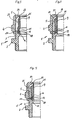
- a cable gland denoted by 1 in all exemplary embodiments has a screw sleeve 2 and a mating sleeve 4, which can thus be connected by means of a thread 3, in which a clamping insert 5, preferably located by means of the axial screwing of the screw sleeve 2 and mating sleeve 4, against a cable or a protective tube arranged inside made of harder material than the cable jacket is radially compressible.
- the mating sleeve 4 overlaps the clamping insert 5 with an annular surface 6, preferably designed as a cone, on an end face 7, so that when the thread 3 is tightened, an area of the clamping insert 5 provided with axial slots 8 opening at the end annular surface 6 due to the action of the conical Formation of the annular surface 6 and the end face 7 radially or the like against the cable. is deformed.
- a seal 9 in the form of a sealing ring or a sealing sleeve is arranged between the clamping insert 5 and the cable and this seal 9 is pressed against the cable by the radial deformation of the clamping insert 5 mentioned.
- the seal 9 is additionally acted upon axially and is therefore supported with its end face 10 facing away from the counter sleeve 4 on a shoulder or a support 11 of the screw sleeve 2.
- the screw sleeve 2 has a inside in the region of the support 11 for the seal 9 its connected, concentric, in relation to the support 11 in the axial direction protruding holding sleeve 12 which engages over the inside 13 of the edge portion 14 of the seal 9 on the screw sleeve side and prevents it from slipping off the support 11.
- the holding sleeve 11 can clearly be seen in all the exemplary embodiments, which overlaps the edge region 14 of the seal 9 on the inside over a certain length and thus prevents radial inward deformation when subjected to axial pressure.
- neither a partial nor a complete slipping off of the support 11 takes place, which would be the case in particular if the outer dimension of the cable were at the lowest limit, which can still be grasped by the cable gland 1, and a certain air or water pressure building on the slots of the clamping insert is effective in the radial direction.
- the sealing insert is also pushed away from the support 11 inwards if this support 11 is not designed to be flat but oblique in its bearing surface, so that a cavity is created.
- the holding sleeve 12 is connected in one piece to the screw sleeve 2. This offers itself both in the case of a screw sleeve 2 made of plastic and of metal, and practically does not increase its production outlay.
- the radial distance between the outside of the holding sleeve 12 and the inside of the cable gland 1 corresponds at least in regions to the thickness of the seal 9 in its end region 14.
- This end region 14 is at the above-mentioned embodiments thus equally inside and outside and accordingly held securely.
- FIGS. 3 to 9 show exemplary embodiments in which the seal 9 is in the region of the holding sleeve 12 has a shoulder 15 which can bear against the end face 16 of the holding sleeve 12, and that the continuation 17 of the seal 9 extending from this shoulder 15 engages between the holding sleeve 12 and the screw sleeve 2.
- the seal 9 is supported even better in the axial direction and can have a greater thickness, in particular in its region which does not engage behind the holding sleeve 12, if this is desired for a greater tolerance when detecting cables of different thicknesses or correspondingly high sealing pressures are to be applied.
- FIG. 10 is an example of how the seal 9 can have a substantially constant annular cross section over its entire length, as also in the embodiment according to FIG. 2.
- the seal 9 is widened radially outward in the region of the holding sleeve 12. It then even receives axial loading in this area an outward component, which is thus directed away from the inner annular gap between the holding sleeve 12 and the cable.
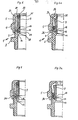
- the radially outer circumferential surface of the holding sleeve 12, which engages under the seal 9, rises from its base or the support region 11 for the seal 9 from the inside to the outside from a smaller to a larger diameter.
- an annular chamber 18, which widens to support the seal 9, is formed between the screw sleeve 2 and the holding sleeve 12. In this widening chamber 18, the end region 14 of the seal 9 can deform when axially loaded, in order to provide an even better anchoring.
- FIG. 7 is an example of the fact that the outside of the holding sleeve 12 can be tapered in both directions by first reducing its diameter starting from the support 11 and then increasing it again.
- Fig. 8 to 10 shows ways to provide the holding sleeve 12 can be inserted into the cable gland 1 and preferably on an inner shoulder 19 of the
- screw sleeve 2 in particular in the axial direction.
- This solution is appropriate if the screw sleeve is made of metal, but in addition the holding sleeve 12 is to serve for the internal insulation of the screw sleeve.
- the holding sleeve 12 has a continuation, facing away from the seal 9, as an insulating sleeve 20, which extends in the axial direction to the end of the screw sleeve 2 facing away from the counter sleeve 3.
- This subsequently usable holding sleeve 2 thus fulfills a double function, in that it overlaps and secures the inside of the front edge area 14 of the seal 9 and insulates the inside of the screw sleeve 2.
- a very special embodiment is shown in FIG. 8, in which the holding sleeve 12 is provided with slots 8 and has a continuation 21 which also encompasses the seal 9 on the outside thereof and which is at the same time designed as an axial slot 8 having a clamping insert 5.
- the holding sleeve 12 is practically connected in one piece to the clamping insert 5 as an additional clamping insert 5, which can already be an advantageous embodiment of the invention.
- the insulating sleeve 20 is then molded on. 8 can be provided with two clamping inserts 5, holding sleeve 12 and insulating sleeve 20 with a single insert part.
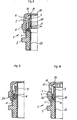
- FIGS. 6 to 7a, 9 and 10 or 14 Another possibility is indicated, for example, in FIGS. 6 to 7a, 9 and 10 or 14.
- the edge region of the holding sleeve 12 which overlaps the seal 9 projects partially below the clamping region of the clamping insert 5 which acts on the seal 9 on its outwardly extending annular extension 26, that is to say in the region of the ring-shaped part Extension 26 shaped clamping insert 5, in which the slots 8 also protrude.
- the seal is also pressed onto the outside of the holding sleeve 12 and is therefore better chambered and held.
- the shape of the seal 9 in the area of its support 11 and overlap by the holding sleeve 12 can be designed in accordance with the annular cavity between the holding sleeve 12 and the screw sleeve 2, that is, as a molded seal. This can be clearly seen in FIGS. 8 and 10 or also in FIGS. 11 to 14 and in simple form in FIG. 1 or 2 or 4. It would also be possible to match the corresponding end regions of the seal 9 to the shape of the chamber 18 For example, adjust the embodiment of FIG. 3 and create a corresponding molded seal that would have to be forced into this chamber when inserted.
- FIGS. 1 and 3 to 10 show how the tightness of the cable gland between the sealing insert 9 and the cable surface can be increased and maintained accordingly.
- the clamping insert 5 overlaps the sealing insert 9 at the end at most three-quarters of its wall thickness, so that the sealing insert is prevented from creeping away by the overlap 24, but the cable surface is not damaged by the overlap 24.
- the sealing insert 9 has a shoulder 25 on its side 22 facing the counter sleeve 4, which led through the overlap 24 of the clamping insert 5 and also when turning protect the cable between the clamping fingers 23 of the clamping insert 5 and the cable surface puts so that the cable is not damaged and the through. the sedimentation of the chambered sealing material cannot creep away even under tensile load.
Landscapes
- Engineering & Computer Science (AREA)
- Architecture (AREA)
- Civil Engineering (AREA)
- Structural Engineering (AREA)
- Installation Of Indoor Wiring (AREA)
- Cable Accessories (AREA)
Applications Claiming Priority (2)
| Application Number | Priority Date | Filing Date | Title |
|---|---|---|---|
| DE3519032A DE3519032C1 (de) | 1985-05-25 | 1985-05-25 | Kabelverschraubung mit einem Klemmeinsatz und einer Dichtung |
| DE3519032 | 1985-05-25 |
Publications (3)
| Publication Number | Publication Date |
|---|---|
| EP0203263A2 true EP0203263A2 (fr) | 1986-12-03 |
| EP0203263A3 EP0203263A3 (en) | 1987-10-21 |
| EP0203263B1 EP0203263B1 (fr) | 1992-04-15 |
Family
ID=6271771
Family Applications (1)
| Application Number | Title | Priority Date | Filing Date |
|---|---|---|---|
| EP86101943A Expired - Lifetime EP0203263B1 (fr) | 1985-05-25 | 1986-02-15 | Accessoire de câble fileté comportant des moyens de serrage et d'étanchéité |
Country Status (2)
| Country | Link |
|---|---|
| EP (1) | EP0203263B1 (fr) |
| DE (2) | DE3519032C1 (fr) |
Cited By (10)
| Publication number | Priority date | Publication date | Assignee | Title |
|---|---|---|---|---|
| FR2611322A1 (fr) * | 1987-02-19 | 1988-08-26 | Conducto | Dispositif d'etancheite et de serrage pour cables |
| US5207602A (en) * | 1989-06-09 | 1993-05-04 | Raychem Corporation | Feedthrough coaxial cable connector |
| US5277598A (en) * | 1992-07-10 | 1994-01-11 | Raychem Corporation | Coaxial cable connection protection system with multiple chambered shroud |
| US5297972A (en) * | 1992-07-10 | 1994-03-29 | Raychem Corporation | Coaxial cable connection protection system |
| US5362250A (en) * | 1992-11-25 | 1994-11-08 | Raychem Corporation | Coaxial cable connection method and device using oxide inhibiting sealant |
| US5435736A (en) * | 1993-09-07 | 1995-07-25 | Raychem Corporation | Coaxial cable connection protection system for unused connection port |
| US5486120A (en) * | 1992-07-10 | 1996-01-23 | Raychem Corporation | Coaxial cable connection protection system with multiple chambered, flexible-webbed shroud |
| ITMI20130472A1 (it) * | 2013-03-28 | 2014-09-29 | Gewiss Spa | Struttura di pressacavo, particolarmente per prese e spine di tipo industriale |
| WO2018019325A1 (fr) * | 2016-07-25 | 2018-02-01 | Pflitsch Gmbh & Co. Kg | Dispositif servant au passage étanche d'une pièce moulée allongée |
| EP3787123A1 (fr) | 2019-08-28 | 2021-03-03 | Etel S. A.. | Ensemble de connexion de blindage de câble pour dispositif électrique |
Families Citing this family (2)
| Publication number | Priority date | Publication date | Assignee | Title |
|---|---|---|---|---|
| DE202007003957U1 (de) | 2007-03-19 | 2008-07-31 | Anton Hummel Verwaltungs-Gmbh | Kabelverschraubung mit Schraubhülse und Überwurfmutter |
| DE102015006521A1 (de) | 2015-05-26 | 2016-12-01 | Jacob Gmbh Elektrotechnische Fabrik | Vorrichtung zur Befestigung einer Leitung |
Family Cites Families (4)
| Publication number | Priority date | Publication date | Assignee | Title |
|---|---|---|---|---|
| DE1750095A1 (de) * | 1968-03-29 | 1971-03-11 | Walter Roehl | Verschraubung fuer Kabel,Schlaeuche u.ae. |
| GB1543678A (en) * | 1976-07-16 | 1979-04-04 | Lapp Kg U | Clamping device for cables leads hoses or the like |
| DE3104974A1 (de) * | 1981-02-12 | 1982-09-16 | U.I. Lapp Kg, 7000 Stuttgart | Einsatz fuer verschraubungen |
| JPS59122305A (ja) * | 1982-12-25 | 1984-07-14 | 日幸工業株式会社 | ケ−ブル類の固定具 |
-
1985
- 1985-05-25 DE DE3519032A patent/DE3519032C1/de not_active Expired
-
1986
- 1986-02-15 DE DE8686101943T patent/DE3684815D1/de not_active Expired - Lifetime
- 1986-02-15 EP EP86101943A patent/EP0203263B1/fr not_active Expired - Lifetime
Cited By (19)
| Publication number | Priority date | Publication date | Assignee | Title |
|---|---|---|---|---|
| FR2611322A1 (fr) * | 1987-02-19 | 1988-08-26 | Conducto | Dispositif d'etancheite et de serrage pour cables |
| US5207602A (en) * | 1989-06-09 | 1993-05-04 | Raychem Corporation | Feedthrough coaxial cable connector |
| US5609501A (en) * | 1989-06-09 | 1997-03-11 | Raychem Corporation | Feed through coaxial cable connector |
| US5486120A (en) * | 1992-07-10 | 1996-01-23 | Raychem Corporation | Coaxial cable connection protection system with multiple chambered, flexible-webbed shroud |
| US5277598A (en) * | 1992-07-10 | 1994-01-11 | Raychem Corporation | Coaxial cable connection protection system with multiple chambered shroud |
| US5297972A (en) * | 1992-07-10 | 1994-03-29 | Raychem Corporation | Coaxial cable connection protection system |
| US5469613A (en) * | 1992-07-10 | 1995-11-28 | Raychem Corporation | Tool for connecting a coaxial cable terminus to a connection jack |
| US5490803A (en) * | 1992-11-25 | 1996-02-13 | Raychem Corporation | Coaxial cable connection method and device using oxide inhibiting sealant |
| US5362250A (en) * | 1992-11-25 | 1994-11-08 | Raychem Corporation | Coaxial cable connection method and device using oxide inhibiting sealant |
| US5435736A (en) * | 1993-09-07 | 1995-07-25 | Raychem Corporation | Coaxial cable connection protection system for unused connection port |
| US5655915A (en) * | 1993-09-07 | 1997-08-12 | Raychem Corporation | Coaxial cable connection protection system for unused connection port |
| ITMI20130472A1 (it) * | 2013-03-28 | 2014-09-29 | Gewiss Spa | Struttura di pressacavo, particolarmente per prese e spine di tipo industriale |
| CN104078792A (zh) * | 2013-03-28 | 2014-10-01 | 哥维斯股份公司 | 用于电气设备的电缆接头组件 |
| EP2784887A1 (fr) * | 2013-03-28 | 2014-10-01 | GEWISS S.p.A. | Ensemble presse-étoupe pour appareil électrique |
| CN104078792B (zh) * | 2013-03-28 | 2018-05-15 | 哥维斯股份公司 | 电缆接头组件以及包括电缆接头组件的电气设备 |
| WO2018019325A1 (fr) * | 2016-07-25 | 2018-02-01 | Pflitsch Gmbh & Co. Kg | Dispositif servant au passage étanche d'une pièce moulée allongée |
| EA037566B1 (ru) * | 2016-07-25 | 2021-04-14 | Пфлич Гмбх Унд Ко. Кг | Устройство для герметичной проводки протяженной детали |
| US11598417B2 (en) | 2016-07-25 | 2023-03-07 | Pflitsch Gmbh & Co. Kg | Device for the sealed passing-through of an elongate part |
| EP3787123A1 (fr) | 2019-08-28 | 2021-03-03 | Etel S. A.. | Ensemble de connexion de blindage de câble pour dispositif électrique |
Also Published As
| Publication number | Publication date |
|---|---|
| DE3684815D1 (de) | 1992-05-21 |
| DE3519032C1 (de) | 1986-10-30 |
| EP0203263B1 (fr) | 1992-04-15 |
| EP0203263A3 (en) | 1987-10-21 |
Similar Documents
| Publication | Publication Date | Title |
|---|---|---|
| DE2902174C2 (de) | Vorrichtung zum Befestigen von Kabeln oder dergleichen an einem Stützteil | |
| DE3216938C2 (de) | Rohrverbindung | |
| EP1959181A1 (fr) | Raccord et ensemble de connexion avec un raccord | |
| EP0203269B1 (fr) | Accessoire de câble fileté | |
| EP0203263B1 (fr) | Accessoire de câble fileté comportant des moyens de serrage et d'étanchéité | |
| DE2750986A1 (de) | Rohrverbindung | |
| DE1963299C3 (de) | Anschluß für mindestens ein druckmittelbeaufschlagtes, ein glattes Ende aufweisendes rohrförmiges Element | |
| EP0165414A2 (fr) | Accessoire de câble fileté | |
| DE2625460A1 (de) | Spaltring, insbesondere fuer eine schlauch- oder rohrkupplung | |
| DE102012102415B4 (de) | Montagesystem für Rohrverschraubungen mit Schneidring | |
| DE20214631U1 (de) | Adapter-Zwischenring für ein Einschraubteil eines Fluid-Stecksystems | |
| DE69203792T2 (de) | Vorrichtung zum abgedichteten Verbinden von rohrförmigen Elementen an Abzweigdosen für elektrische Komponenten. | |
| CH705378B1 (de) | Kabelverschraubung. | |
| EP1780854A1 (fr) | Presse-étoupe pour câble ou tuyau | |
| EP0152617A2 (fr) | Dispositif d'étanchéité | |
| DE1943885B2 (de) | Verbindungselement für zwei elektromagnetische Hohlleiter | |
| EP2716824A2 (fr) | Tuyau, notamment tuyau de douche | |
| DE102012212023A1 (de) | Kabelverschraubung | |
| DE2513982B2 (de) | Rohrdichtung | |
| EP0640786B1 (fr) | Raccord à vis combiné pour câble et tuyau souple | |
| DE3031687C2 (de) | Vorrichtung zum Schutz der Endbereiche von Rohren gegen mechanische Beschädigungen | |
| DE9102824U1 (de) | Vorrichtung zum Abdichten der Enden von Kabelschutzrohren | |
| DE3601597A1 (de) | Vorrichtung zum befestigen eines gegenstandes an einer wand oder dgl. | |
| DE202011004544U1 (de) | Pressverbindung für Kunststoffrohre | |
| EP2667074A1 (fr) | Système de connexion de tuyaux avec clip de serrage |
Legal Events
| Date | Code | Title | Description |
|---|---|---|---|
| PUAI | Public reference made under article 153(3) epc to a published international application that has entered the european phase |
Free format text: ORIGINAL CODE: 0009012 |
|
| AK | Designated contracting states |
Kind code of ref document: A2 Designated state(s): CH DE FR GB IT LI |
|
| PUAL | Search report despatched |
Free format text: ORIGINAL CODE: 0009013 |
|
| AK | Designated contracting states |
Kind code of ref document: A3 Designated state(s): CH DE FR GB IT LI |
|
| 17P | Request for examination filed |
Effective date: 19880324 |
|
| 17Q | First examination report despatched |
Effective date: 19900925 |
|
| RAP1 | Party data changed (applicant data changed or rights of an application transferred) |
Owner name: ANTON HUMMEL VERWALTUNGS-GMBH |
|
| GRAA | (expected) grant |
Free format text: ORIGINAL CODE: 0009210 |
|
| AK | Designated contracting states |
Kind code of ref document: B1 Designated state(s): CH DE FR GB IT LI |
|
| REF | Corresponds to: |
Ref document number: 3684815 Country of ref document: DE Date of ref document: 19920521 |
|
| ITF | It: translation for a ep patent filed | ||
| ET | Fr: translation filed | ||
| GBT | Gb: translation of ep patent filed (gb section 77(6)(a)/1977) | ||
| PLBE | No opposition filed within time limit |
Free format text: ORIGINAL CODE: 0009261 |
|
| STAA | Information on the status of an ep patent application or granted ep patent |
Free format text: STATUS: NO OPPOSITION FILED WITHIN TIME LIMIT |
|
| 26N | No opposition filed | ||
| REG | Reference to a national code |
Ref country code: GB Ref legal event code: IF02 |
|
| PGFP | Annual fee paid to national office [announced via postgrant information from national office to epo] |
Ref country code: FR Payment date: 20041229 Year of fee payment: 20 |
|
| PGFP | Annual fee paid to national office [announced via postgrant information from national office to epo] |
Ref country code: DE Payment date: 20050201 Year of fee payment: 20 |
|
| PGFP | Annual fee paid to national office [announced via postgrant information from national office to epo] |
Ref country code: GB Payment date: 20050208 Year of fee payment: 20 |
|
| PGFP | Annual fee paid to national office [announced via postgrant information from national office to epo] |
Ref country code: CH Payment date: 20050218 Year of fee payment: 20 |
|
| PGFP | Annual fee paid to national office [announced via postgrant information from national office to epo] |
Ref country code: IT Payment date: 20050225 Year of fee payment: 20 |
|
| PG25 | Lapsed in a contracting state [announced via postgrant information from national office to epo] |
Ref country code: GB Free format text: LAPSE BECAUSE OF EXPIRATION OF PROTECTION Effective date: 20060214 |
|
| REG | Reference to a national code |
Ref country code: GB Ref legal event code: PE20 |
|
| REG | Reference to a national code |
Ref country code: CH Ref legal event code: PL |