EP0203433A2 - Handhebel-Fettpresse - Google Patents
Handhebel-Fettpresse Download PDFInfo
- Publication number
- EP0203433A2 EP0203433A2 EP86106335A EP86106335A EP0203433A2 EP 0203433 A2 EP0203433 A2 EP 0203433A2 EP 86106335 A EP86106335 A EP 86106335A EP 86106335 A EP86106335 A EP 86106335A EP 0203433 A2 EP0203433 A2 EP 0203433A2
- Authority
- EP
- European Patent Office
- Prior art keywords
- hand lever
- bore
- pressure part
- grease gun
- piece
- Prior art date
- Legal status (The legal status is an assumption and is not a legal conclusion. Google has not performed a legal analysis and makes no representation as to the accuracy of the status listed.)
- Withdrawn
Links
Images

Classifications
-
- F—MECHANICAL ENGINEERING; LIGHTING; HEATING; WEAPONS; BLASTING
- F16—ENGINEERING ELEMENTS AND UNITS; GENERAL MEASURES FOR PRODUCING AND MAINTAINING EFFECTIVE FUNCTIONING OF MACHINES OR INSTALLATIONS; THERMAL INSULATION IN GENERAL
- F16N—LUBRICATING
- F16N3/00—Devices for supplying lubricant by manual action
- F16N3/10—Devices for supplying lubricant by manual action delivering grease
- F16N3/12—Grease guns
-
- Y—GENERAL TAGGING OF NEW TECHNOLOGICAL DEVELOPMENTS; GENERAL TAGGING OF CROSS-SECTIONAL TECHNOLOGIES SPANNING OVER SEVERAL SECTIONS OF THE IPC; TECHNICAL SUBJECTS COVERED BY FORMER USPC CROSS-REFERENCE ART COLLECTIONS [XRACs] AND DIGESTS
- Y10—TECHNICAL SUBJECTS COVERED BY FORMER USPC
- Y10T—TECHNICAL SUBJECTS COVERED BY FORMER US CLASSIFICATION
- Y10T29/00—Metal working
- Y10T29/49—Method of mechanical manufacture
- Y10T29/49229—Prime mover or fluid pump making
- Y10T29/49236—Fluid pump or compressor making
Definitions
- the invention relates to a hand lever grease gun with a low-pressure piston grease container and with a high-pressure piston in a bore of a high-pressure part, which is arranged on a screw-on lid of the grease container, communicates via a bore with the inside of the grease container and one across the high-pressure piston has standing outlet nozzle with a bore and a valve, and wherein a hand lever is articulated on the high-pressure piston and on a swivel bracket, which in turn is mounted on the high-pressure part.
- Hand lever grease guns of the type mentioned are known, for example, from the two US Pat. Nos. 3,627,178 and 4,077,494 and are used in large numbers. They are filled after unscrewing the lid and have a low-pressure piston that presses the grease into the high-pressure part. With the help of the hand lever mounted on the high-pressure part and displacing the high-pressure piston, the grease is pressed out of the high-pressure part, due to of the effective transmission ratio on the hand lever very high pressures can be achieved.
- the high-pressure part in the hand lever grease gun shown and described in US Pat. No. 3,627,178 consists of a pipe section, the outlet connection piece and a sealing plug.
- the outlet nozzle has a through hole lying in the extension of the pipe section, closed at one end with the aid of the sealing plug, and an outlet hole transversely thereto.
- the outlet nozzle is attached to one end face of the pipe section with the aid of a circumferential weld seam.
- both the cylinder and the outlet nozzle also have transverse bores so that the cylinder can receive the outlet nozzle and the grease under high pressure can enter the outlet nozzle.
- the outlet connector is attached to the cylinder by rivet-like widening of its one end.
- hand lever grease guns with a quadrangular cross-section and a cylindrical bore are known: high-pressure part, on which one serves as an outlet connection; serving pipe section is either welded or fastened by means of a screw connection.
- high-pressure part on which one serves as an outlet connection
- serving pipe section is either welded or fastened by means of a screw connection.
- weld seam and in particular the screw connection are not without problems because of the raw pressures, because there is only little space for the required threads in the area of the connection point for the outlet connection.
- a hand lever grease gun is known from DE-OS 14 75 542, the high-pressure part including outlet nozzle and cover element consist of a single piece. Gray cast iron, die-cast aluminum, die-cast zinc or plastic can be used as the material. However, none of these cases ensures the desirable durability or precision that can be achieved with a steel part.
- the object of the invention is to provide measures with which the manufacture of the high-pressure part can be simplified and, at the same time, a maximum degree of operational safety can be achieved in view of the pressures that occur.
- the invention provides that the high-pressure part and the outlet piece in one-piece design is an L-shaped, pressed and bored round material piece made of steel.
- the starting material is preferably wire rod, which is cut into pieces, bent into an L-shape and pressed in such a way that it has sufficient contact surfaces which allow it to be attached to the lid. Furthermore, the holes for the high-pressure piston in the long leg and for the outlet in the short leg can be provided without any problems, the hole for the high-pressure piston not being completed until it has been attached to the cover.
- the high-pressure part has a cutting edge bearing for the swivel bracket on its outlet end.
- the swivel bracket is therefore no longer supported on an axle or rivet, but with the aid of a web that delimits a recess that overlaps the outlet connector and lies in a bearing notch that forms the cutting edge bearing.
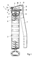
- a hand lever grease gun 1 comprises a grease container 2 with a low pressure piston 3 and a high pressure part 4 with a bore 5, in which a high pressure piston 6 Is axially displaceable with the aid of a hand lever 7.
- the high-pressure part 4 is arranged on a cover 8 which can be screwed onto the grease container 2 and its bore 5 communicates with the interior 9 of the grease container 2 via an opening 10 and an opening 11 in the cover 8.
- the bore 5 is a blind bore.
- the high-pressure part 4 further comprises an outlet connection 12 which is transverse to the high-pressure piston 6 and has a stepped bore 13 and a valve 14 with a valve spring 15.
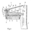
- the high-pressure part 4 and its outlet nozzle 12 consist in one piece of an L-shaped bent and pressed and provided with the opening 10 or the holes 5 and 13 round piece of material 16.
- This piece of round material 16 is made of steel and is preferably a piece of wire rod that is used for production of the high-pressure part 4 is first cut into pieces of suitable length, bent in an L-shape and then provided with a flat bottom surface 17 by pressing or pressing.
- the outlet connector 12 is crowned on the outside and also receives a bearing notch 18 and expediently a material shift 19 when the opening 10 is pressed in.
- the bores 5 and 13 are also introduced, the bore 5 having its finished dimension only after the high-pressure part 4 has been attached to the cover 8 receives.
- the hand lever 7 is articulated on the high-pressure piston 6 and on a swivel bracket 20 with the aid of bolts 21 and 22, respectively.
- a cutting edge bearing serves to mount the swivel bracket 20 on the high-pressure part 4.
- the swivel bracket 20 has an overlap from the outlet connection 12 Take 23 and a lying in the bearing notch 18 on the outside of the high pressure part 4 and the outlet 12 web 24.
- This web 24 expediently consists of a double material layer of the cross-section, for example U-shaped swivel tab 2 0 . ;
- the surface of the outlet connector 12 opposite the bearing notch 18 is preferably slightly spherical, so that the edge 26 of the recess 23 resting there can be supported as frictionlessly as possible when the high-pressure piston 6 is pulled out of the bore 5. Finally, a low level of friction is also present in the cutting edge bearing between the web 24 and the bearing notch 18.
- FIGS. 3 and 4 differs from the first described embodiment only in that the bolt 21 connecting the hand lever 7 to the swivel bracket 20 according to FIG. 2 is replaced by a further cutting edge bearing 27.
- the web of the swivel plate 2o a U-shaped recess 29, in which slots 3 0, 31 and 32, the free edges 33 and 34 of the legs 35, 36 and the angled off edge 37 of the web 38 of the in cross section even! if U-shaped hand lever 7a.
- the free edges 33, 34 of the legs 35, 36 also run slightly obliquely or at an acute angle to the web 28 of the swivel tab 2o a and engage with edge pieces 39, 4o as far as under the web 28.
Landscapes
- Engineering & Computer Science (AREA)
- General Engineering & Computer Science (AREA)
- Mechanical Engineering (AREA)
- Coating Apparatus (AREA)
Abstract
Description
- Die Erfindung betrifft eine Handhebel-Fettpresse mit einem einen Niederdruckkolben aufweisenden Fettbehälter sowie mit einem Hochdruckkolben in einer Bohrung eines Hochdruckteiles, das an einem auf den Fettbehälter aufschraubbaren Deckel angeordnet ist, über eine Bohrung mit dem Inneren des Fettbehälters in Verbindung steht und einen quer zum Hochdruckkolben stehenden Auslaßstutzen mit einer Bohrung und einem Ventil aufweist, und wobei ein Handhebel am Hochdruckkolben und an einer Schwenklasche angelenkt ist, die wiederum am Hochdruckteil gelagert ist.
- Handhebel-Fettpressen der genannten Art sind z.B. aus den beiden US-PS 3 627 178 und 4 o77 494 bekannt und gelangen in großen Stückzahlen zum Einsatz. Sie werden nach Abschrauben des Deckels gefüllt und weisen einen Niederdruckkolben auf, der das Fett in den Hochdruckteil drückt. Mit Hilfe des am Hochdruckteil gelagerten und den Hochdruckkolben verschiebenden Handhebels wird das Fett aus dem Hochdruckteil herausgepreßt, wobei aufgrund des am Handhebel wirksamen Übersetzungsverhältnisses sehr hohe Drücke erzielbar sind.
- Der Hochdruckteil besteht bei der in der US-PS 3 627178 dargestellten und beschriebenen Handhebel-Fettpresse aus einem Rohrstück, dem Auslaßstutzen und einem Verschlußstopfen. Der Auslaßstutzen weist eine in VerLängerung des Rohrstückes liegende, an ihrem einen Ende mit Hilfe des Verschlußstopfens geschlossene Durchgangsbohrung und quer dazu eine Auslaßbohrung auf. Die Befestigung des Auslaßstutzens erfolgt an der einen Stirnfläche des Rohrstückes mit Hilfe einer umlaufenden Schweißnaht.
- Bei der Handhebel-Fettpresse nach der US-PS 4 077 494 besteht der Hochdruckteil aus einem Zylinder und einem Auslaßstutzen, der den Zylinder in der Nähe seines Bodens durchgreift. Sowohl der Zylinder als auch der Auslaßstutzen weisen zusätzlich zu ihren Längsbohrungen auch Querbohrungen auf, damit einerseits der Zylinder den Auslaßstutzen aufnehmen kann und andererseits das unter hohem Druck stehende Fett in den Auslaßstutzen eintreten kann. Die Befestigung des Auslaßstutzens am Zylinder erfolgt durch nietartiges Aufweiten seines einen Endes.
- In dem Hochdruckteil und somit auch an der Verbindungsstelle zwischen dem Auslaßstutzen und dem Rohrstück bzw. dem Zylinder treten während des Betriebes Drücke bis 4oo bar auf. Die Prüfung der Funktionssicherheit erfolgt sogar bei einem Druck von 800 bar. Die Herstellung des Hochdruckteiles muß daher mit großer Sorgfalt erfolgen, da jede Fehlerstelle an der Schweißnaht bzw. an dem nietartigen Endstück sofort zu Undichtigkeiten und somit zur völligen Unbrauchbarkeit des Gerätes führt.
- Ferner sind Handhebel-Fettpressen mit einem im Querschnitt vierecken, eine zylindrische Bohrung aufweisenden : Hochdruckteil bekannt, an dem ein als Auslaßstutzen ; dienendes Rohrstück entweder angeschweißt oder mittels einer Schraubverbindung befestigt ist. Auch hier ist die Schweißnaht und insbesondere die Schraubverbindung wegen der rohen Drücke nicht unproblematisch, weil im Bereich der Anschlußstelle für den Auslaßstutzen nur wenig Platz für die erforderlichen Gewindegänge vorhanden ist.
- Sowohl bei der zuletzt genannten Handhebel-Fettpresse als auch bei der aus der US-PS 3 627 178 bekannten Handhebel-Fettpresse ist die den Handhebel lagernde Schwenklasche am Hochdruckteil mit Hilfe eines Niet befestigt. Die Bohrung für den Niet befindet sich entweder in dem Auslaßstutzen oder in dem Hochdruckteil. ;
- Schließlich ist aus der DE-OS 14 75 542 eine Handhebel-Fettpresse bekannt, deren Hochdruckteil einschließlich Auslaßstutzen und Deckelelement aus einem einzigen Stück bestehen. Als Werkstoff können Grauguß, Aluminiumdruck- guß, Zinkdruckguß oder Kunststoff dienen. Allerdings ist in keinem dieser Fälle die wünschenswerte Haltbarkeit oder Präzision gewährleistet, die bei einem Teil aus Stahl erzielbar ist.
- Der Erfindung liegt gegenüber dem insgesamt genannten Stand der Technik die Aufgabe zugrunde, Maßnahmen vorzusehen, mit deren Hilfe dich-die Fertigung des Hochdruckteiles vereinfachen läßt und gleichzeitig ein Höchstmaß an Betriebssicherheit in Anbetracht der auftretenden Drücke erzielbar ist.
- Zur Lösung dieser Aufgabe sieht die Erfindung vor, daß der Hochdruckteil und der Auslaßstutzen in einstückiger Ausbildung ein L-förmig gebogenes und gepresstes sowie mit Bohrungen versehenes Rundmaterialstück aus Stahl ist.
- Durch die Einstückigkeit und die Verwendung von Stahl entfallen alle bisher bestehenden Probleme. Undichte und zum Bersten neigende Stelle sind nicht mehr vorhanden. Ferner läßt sich die gewünschte Präzision und Haltbarkeit erreichen. Die Nachteile der bekannten, aus mehreren Stücken bestehenden Hochdruckteile und die Nachteile der bekannten einstückigen Hochdruckteile entfallen daher.
- Als Ausgangsmaterial dient vorzugsweise Walzdraht, der in Stücke geschnitten, L-förmig gebogen und derart gepresst wird, daß er in ausreichendem Maße Auflageflächen aufweist, die seine Befestigung am Deckel gestatten. Ferner lassen sich die Bohrungen für den Hochdruckkolben im langen Schenkel und für den Auslaß im kurzen Schenkel problemlos vorsehen, wobei die Bohrung für den Hochdruckkolben erst nach der Befestigung am Deckel fertiggestellt wird.
- Die Herstellung eines Hochdruckteiles aus einem Walzdrahtstück ist im Ergebnis kostengünstig und bringt ein höheres Maß an Sicherheit mit sich als die bekannten Hochdruckteile.
- Die Herstellungskosten lassen sich schließlich nochmals senken, wenn in Weiterbildung der Erfindung der Hochdruckteil an seinem auslaßseitigen Ende außen ein Schneidenlager für die Schwenklasche aufweist. Die Schwenklasche ist daher nicht mehr auf einer Achse bzw. einem Niet gelagert, sondern mit Hilfe eines Steges, der eine den Auslaßstutzen übergreifende Ausnehmung begrenzt und in einer das Schneidenlager bildenden Lagerkerbe liegt.
- Weitere Merkmale der Erfindung gehen aus der Beschreibung und den Ansprüchen im Zusammenhang mit der Zeichnung hervor.
- Die Erfindung wird nachstehend anhand von Ausführungsbeispielen, die in der Zeichnung dargestellt sind, näher beschrieben. Dabei zeigen:
- Fig. 1 : eine Handhebel-Fettpresse zum Teil im Schnitt;
- Fig. 2 : einen Längsschnitt durch den Hochdruckteil in größerem Maßstab;
- Fig. 3 : einen Schnitt wie in Fig. 2 von einem abgewandelten Ausführungsbeispiel und
- Fig. 4 : eine Draufsicht auf eine Einzelheit gemäß Fig. 3.
- Eine Handhebel-Fettpresse 1 umfaßt einen Fettbehälter 2 mit einem Niederdruckkolben 3 und einen Hochdruckteil 4 mit einer Bohrung 5, in der ein Hochdruckkolben 6 mit Hilfe eines Handhebels 7 axial verschiebbar ist. Der Hochdruckteil 4 ist an einem auf den Fettbehälter 2 aufschraubbaren Deckel 8 angeordnet und seine Bohrung 5 steht mit dem Inneren 9 des Fettbehälters 2 über eine Öffnung 10 und eine Öffnung 11 im Deckel 8 in Verbindung. Die Bohrung 5 ist eine Sackbohrung.
- Der Hochdruckteil 4 umfasst ferner einen quer zum Hochdruckkolben 6 stehenden Auslaßstutzen 12 mit einer abgesetzten Bohrung 13 und einem Ventil 14 mit einer Ventilfeder 15.
- Der Hochdruckteil 4 und sein Auslaßstutzen 12 bestehen in einstückiger Ausbildung aus einem L-förmig gebogenen sowie gepressten und mit der Öffnung 10 bzw. den Bonrungen 5 und 13 versehenen Rundmaterialstück 16. Dieses Rundmaterialstück 16 besteht aus Stahl und ist vorzugsweise ein Walzdrahtstück, das zur Herstellung des Hoch- i druckteiles 4 zunächst in Stücke geeigneter Länge geschnitten, L-förmig gebogen und sodann durch Drücken bzw. Pressen mit einer ebenen Bodenfläche 17 versehen wird. Der Auslaßstutzen 12 wird außen ballig gedrückt und erhält ebenfalls durch Drücken eine Lagerkerbe 18 und zweckmäßigerweise eine Materialverlagerung 19 beim Eindrücken der Öffnung 10.Ferner werden die Bohrungen 5 und 13 eingebracht, wobei die Bohrung 5 ihr Fertigmaß erst nach Befestigung des Hochdruckteiles 4 am Deckel 8 erhält.
- Der Handhebel 7 ist an dem Hochdruckkolben 6 sowie an einer Schwenklasche 20 mit Hilfe von Bolzen 21 bzw. 22 angelenkt. Zur Lagerung der Schwenklasche 20 am Hochdruckteil 4 dient ein Schneidenlager. Die Schwenklasche 20 weist hierzu eine den Auslaßstutzen 12 übergreifende Ausnehmung 23 und einen in der Lagerkerbe 18 außen an dem Hochdruckteil 4 bzw. dem Auslaßstutzen 12 liegenden Steg 24 auf. Dieser Steg 24 besteht zweckmäßigerweise aus einer doppelten Materiallage der im Querschnitt z.B. U-förmigen Schwenklasche 20. ;
- Die der Lagerkerbe 18 gegenüberliegende Oberfläche des Auslaßstutzens 12 ist vorzugsweise leicht ballig, damit sich der dort anliegende Rand 26 der Ausnehmung 23 beim Herausziehen des Hochdruckkolbens 6 aus der Bohrung 5 möglichst reibungsfrei abstützen kann. Eine geringe Reibung ist schließlich auch bei der Schneidenlagerung zwischen dem Steg 24 und der Lagerkerbe 18 gegeben.
- Das in den Fig. 3 und 4 dargestellte Ausführungsbeispiel unterscheidet sich von der zuerst beschriebenen Ausfüh- rungsform nur dadurch, daß der den Handhebel 7 mit der Schwenklasche 2o verbindende Bolzen 21 gemäß Fig. 2 durch ein weiteres Schneidenlager 27 ersetzt ist. Hierzu weist der Steg 28 der Schwenklasche 2o a eine U-förmige Ausnehmung 29 auf, in deren Schlitzen 30, 31 bzw. 32 die freien Ränder 33 und 34 der Schenkel 35, 36 bzw. der ab- gewinkelte Rand 37 des Steges 38 des im Querschnitt eben- ! falls U-förmigen Handhebels 7a liegen. Die freien Ränder 33, 34 der Schenkel 35, 36 verlaufen ferner leicht schräg bzw. spitzwinklig zum Steg 28 der Schwenklasche 2o a und greifen mit Randstücken 39, 4o bis unter den Steg 28. Dadurch sind im Bereich der Schenkel 35, 36 Abstützflächen geschaffen. Ferner liegt der durch den Schlitz 32 greifende, abgewinkelte Rand 37 des Handhebels 7a auf einem umgebördelten Randstück 41 des Steges 28 der Schwenklasche 2o a auf. Die Schwenklasche 2oa und der Handhebel 7a sind daher in Verbindung mit dem Bolzen 22 unlösbar mit- ] einander verbunden, wobei der in dem Schlitz 32 liegende Teil des auswärts abgewinkelten Randes 37 das eigentliche Schneidenlager 27 bildet.
Claims (12)
Applications Claiming Priority (2)
| Application Number | Priority Date | Filing Date | Title |
|---|---|---|---|
| DE3517123A DE3517123C2 (de) | 1985-05-11 | 1985-05-11 | Handhebel-Fettpresse |
| DE3517123 | 1985-05-11 |
Publications (2)
| Publication Number | Publication Date |
|---|---|
| EP0203433A2 true EP0203433A2 (de) | 1986-12-03 |
| EP0203433A3 EP0203433A3 (de) | 1988-01-27 |
Family
ID=6270561
Family Applications (1)
| Application Number | Title | Priority Date | Filing Date |
|---|---|---|---|
| EP86106335A Withdrawn EP0203433A3 (de) | 1985-05-11 | 1986-05-09 | Handhebel-Fettpresse |
Country Status (4)
| Country | Link |
|---|---|
| US (1) | US4676409A (de) |
| EP (1) | EP0203433A3 (de) |
| DE (1) | DE3517123C2 (de) |
| ES (1) | ES8900023A1 (de) |
Families Citing this family (8)
| Publication number | Priority date | Publication date | Assignee | Title |
|---|---|---|---|---|
| US5067591A (en) * | 1989-11-09 | 1991-11-26 | Pentair, Incorporated | Combination air/manual economy grease dispenser |
| US5398847A (en) * | 1992-05-18 | 1995-03-21 | Riso Kagaku Corporation | Cylinder/piston type fluid container |
| US6467579B1 (en) * | 1997-03-22 | 2002-10-22 | Mato Maschinen-Und Metallwarenfabrik Curt Matthaei Gmbh & Co. Kg | Press for compressing lubricating grease and the cartridges used therefor |
| TWM273665U (en) * | 2005-03-17 | 2005-08-21 | Tien-Chen Tung | Pressure relief valve structure of a grease gun |
| US20080029549A1 (en) * | 2006-08-03 | 2008-02-07 | Hulden Richard M | Grease gun |
| US9062826B2 (en) * | 2012-06-12 | 2015-06-23 | Michael C. Ryan | Refillable and rechargeable grease gun reservoir |
| DE202012103332U1 (de) * | 2012-08-31 | 2013-12-02 | Frank Maser | Fettpresse |
| DE102015016821A1 (de) * | 2015-12-23 | 2017-06-29 | Pressol - Schmiergeräte GmbH | Schmierstoffpresse, Schmierstoffpressen-Set und Verwendung einer Kartusche bei einer Schmierstoffpresse |
Family Cites Families (18)
| Publication number | Priority date | Publication date | Assignee | Title |
|---|---|---|---|---|
| US1608748A (en) * | 1925-06-01 | 1926-11-30 | Walter F Hundemer | Detachable booster pump for grease guns |
| US1662842A (en) * | 1926-04-26 | 1928-03-20 | Rogers Products Co Inc | Lubricating apparatus |
| GB276474A (en) * | 1926-07-01 | 1927-09-01 | Walter Frank Hundemer | Improvement in combination grease gun and booster pump |
| US1750150A (en) * | 1927-05-12 | 1930-03-11 | Rogers Products Co Inc | High-power grease gun |
| US1870497A (en) * | 1930-06-10 | 1932-08-09 | Reliance Machine & Stamping Wo | Pressure grease gun |
| GB450436A (en) * | 1935-10-16 | 1936-07-17 | Emma Bach | Improvements in or relating to force-feed lubricators |
| US2340479A (en) * | 1943-04-29 | 1944-02-01 | Lidseen Gustave | Pump feed oilcan |
| GB576038A (en) * | 1943-12-30 | 1946-03-15 | Tecalemit Ltd | Improvements in lubricating apparatus |
| US2612296A (en) * | 1946-03-22 | 1952-09-30 | Stewart Warner Corp | Combined grease pump and reservoir |
| US2436701A (en) * | 1946-06-20 | 1948-02-24 | Edwin P Sundholm | Grease-gun head construction |
| US3209958A (en) * | 1962-05-04 | 1965-10-05 | Southwest Grease & Oil Co Inc | Grease gun head assembly |
| US3176624A (en) * | 1963-02-01 | 1965-04-06 | Southwest Grease & Oil Co Inc | Outlet check valve means for a grease gun head |
| US3338478A (en) * | 1964-07-31 | 1967-08-29 | Ama Produkter Aktiebolag | Lubricating gun and a grease container intended for the same |
| US3627178A (en) * | 1969-09-02 | 1971-12-14 | Edwin P Sundholm | Dispensing head for lever-operated hand grease gun |
| US4077494A (en) * | 1976-12-15 | 1978-03-07 | Parker-Hannifin Corporation | Grease gun |
| US4168787A (en) * | 1977-11-18 | 1979-09-25 | Superior, Inc. | Variable stroke fluid lubricant dispenser |
| DE2815699C3 (de) * | 1978-04-12 | 1981-12-24 | Jakob Preßl Söhne, 8500 Nürnberg | Fettpresse |
| DE8435373U1 (de) * | 1984-12-03 | 1985-04-04 | Pressol Schmiergeräte GmbH, 8500 Nürnberg | Schmierpresse mit Hochdruckraum |
-
1985
- 1985-05-11 DE DE3517123A patent/DE3517123C2/de not_active Expired
-
1986
- 1986-04-29 US US06/857,294 patent/US4676409A/en not_active Expired - Fee Related
- 1986-05-09 EP EP86106335A patent/EP0203433A3/de not_active Withdrawn
- 1986-05-09 ES ES554796A patent/ES8900023A1/es not_active Expired
Also Published As
| Publication number | Publication date |
|---|---|
| EP0203433A3 (de) | 1988-01-27 |
| DE3517123C2 (de) | 1987-05-14 |
| DE3517123A1 (de) | 1986-11-13 |
| ES554796A0 (es) | 1988-11-16 |
| US4676409A (en) | 1987-06-30 |
| ES8900023A1 (es) | 1988-11-16 |
Similar Documents
| Publication | Publication Date | Title |
|---|---|---|
| DE3828692C2 (de) | ||
| DE69403366T2 (de) | Ventilstössel mit Rolle | |
| CH668629A5 (de) | Rohrverschraubung mit beruehrungsdichtung. | |
| DE2535315A1 (de) | Komprimiervorrichtung | |
| DE4002558C2 (de) | Hydraulikzylinder | |
| EP0203433A2 (de) | Handhebel-Fettpresse | |
| DE3016231C2 (de) | Dichtungsanordnung | |
| EP1110017A1 (de) | REIBUNGSARME DICHTUNG und hydraulikzylinder | |
| DE3120812C2 (de) | Radialkolbenverdichter | |
| DE8608673U1 (de) | Federndes Druckstück | |
| EP1769176B1 (de) | Dichtungsanordnung | |
| DE1806665C3 (de) | Verfahren und Vorrichtung zum Befestigen von Muffen aus Metall an gerippten Bewehrungsstäben und nach dem Verfahren hergestellte Stoßverbindung | |
| DE3034115C2 (de) | Leistungsregler | |
| DE4040151A1 (de) | Hebelwerk, insbesondere fusshebelwerk fuer kraftfahrzeuge | |
| EP1621289A2 (de) | Spannzylinder in Kompaktbauweise | |
| DE2649524A1 (de) | Teleskopartige vorrichtung | |
| CH623894A5 (en) | Hydraulic screw machine | |
| DE2448657C3 (de) | Gelenk, insbesondere Schwenkgelenk für einen Abfederungsarm eines Fahrzeugrades | |
| DE3506203C2 (de) | ||
| DE2359306C3 (de) | Hvdropneumatisches Federelement für Fahrzeuge | |
| AT404393B (de) | Arbeitszylinder | |
| DE69413797T2 (de) | Verschlussventil für eine selbsteinstellende hydraulische einrichtung | |
| DE19906690B4 (de) | Dichtring | |
| DE3033739A1 (de) | Druckuebersetzer zur hoechstdruckerzeugung | |
| DE8914037U1 (de) | Durchbiegungseinstellwalze |
Legal Events
| Date | Code | Title | Description |
|---|---|---|---|
| PUAI | Public reference made under article 153(3) epc to a published international application that has entered the european phase |
Free format text: ORIGINAL CODE: 0009012 |
|
| AK | Designated contracting states |
Kind code of ref document: A2 Designated state(s): BE CH FR GB IT LI NL SE |
|
| PUAL | Search report despatched |
Free format text: ORIGINAL CODE: 0009013 |
|
| AK | Designated contracting states |
Kind code of ref document: A3 Designated state(s): BE CH FR GB IT LI NL SE |
|
| 17P | Request for examination filed |
Effective date: 19880215 |
|
| 17Q | First examination report despatched |
Effective date: 19880915 |
|
| STAA | Information on the status of an ep patent application or granted ep patent |
Free format text: STATUS: THE APPLICATION HAS BEEN WITHDRAWN |
|
| 18W | Application withdrawn |
Withdrawal date: 19890119 |
|
| RIN1 | Information on inventor provided before grant (corrected) |
Inventor name: DER ERFINDER HAT AUF SEINE NENNUNG VERZICHTET. |