EP0203451A2 - Gurtrückhaltevorrichtung - Google Patents
Gurtrückhaltevorrichtung Download PDFInfo
- Publication number
- EP0203451A2 EP0203451A2 EP86106517A EP86106517A EP0203451A2 EP 0203451 A2 EP0203451 A2 EP 0203451A2 EP 86106517 A EP86106517 A EP 86106517A EP 86106517 A EP86106517 A EP 86106517A EP 0203451 A2 EP0203451 A2 EP 0203451A2
- Authority
- EP
- European Patent Office
- Prior art keywords
- harness
- emergency
- strap
- actuation
- assembly
- Prior art date
- Legal status (The legal status is an assumption and is not a legal conclusion. Google has not performed a legal analysis and makes no representation as to the accuracy of the status listed.)
- Withdrawn
Links
Images


Classifications
-
- B—PERFORMING OPERATIONS; TRANSPORTING
- B64—AIRCRAFT; AVIATION; COSMONAUTICS
- B64D—EQUIPMENT FOR FITTING IN OR TO AIRCRAFT; FLIGHT SUITS; PARACHUTES; ARRANGEMENT OR MOUNTING OF POWER PLANTS OR PROPULSION TRANSMISSIONS IN AIRCRAFT
- B64D25/00—Emergency apparatus or devices, not otherwise provided for
- B64D25/02—Supports or holding means for living bodies
- B64D25/06—Harnessing
Definitions
- the present invention relates to the art of harness restraint systems, and, in particular, to an improved system which provides safety and comfort to seat occupants, especially those in high performance aircraft.
- One type of system which has been found particularly convenient includes a single-point release mechanism to which all harness latch plates terminating the belts of the restraint system can be connected at a point at the center of the body below the rib cage. See, for example, U.K. Patent Specification No. 915,168 of Harley Patents (International) Limited, which discloses a single point release mechanism.
- a single-point release system of this type has advantages over parallel strap multi-connection systems, such as accessibility to either hand of the occupant and ease of operation.
- a single-point release as described above has the obvious advantage of facilitating egress from the aircraft, or in releasing the parachute harness, since the occupant must be able to separate instantly under emergency conditions as in the case of fire or ocean ditching.
- the occupant must be able to detach from the harness in a loaded condition which can result from being suspended, e.g., from a tree, or in an inverted position.
- a restraint harness is being designed to reduce vertical "z” and lateral "y” displacement in ejection seats and parachute harnesses for which the single-point release system can . readily be adapted.
- the present invention is directed to an improved harness restraint system for a seat occupant in a vehicle which includes a single-point release device having at least two releasable connectors laterally separated, but which can be actuated from a single point to release harness strap plates connected to the connectors.
- the present system also can include harness shoulder straps which cross diagonally over the chest of the occupant while in use and terminate in harness strap plates for attachment to the laterally separated releasable connectors.
- the restraint system of the present invention can also include two additional laterally spaced releasable connectors on the bottom of the single-point release device for attachment of lower body straps thereto.
- the restraint system can in one embodiment also include harness leg straps, each of which encircles a leg of the occupant and terminates attachment to the two additional laterally-spaced releasable connectors.
- the harness straps of the present invention can include gross adjustment devices for pre-adjustment of the harness belt to approximate occupant's size, and be adjustable for all sizes when connected.
- This unique feature of the present invention is a harness strap device adaptable for harness assemblies requiring strap adjustment, and can include a harness belt adjustment means having an indicator viewing window which is adapted for fixed attachment to a harness assembly, and an indicator harness strap marked with indicators corresponding to adjustment lengths that accommodate different body sizes. for the particular harness assembly.
- the indicator harness strap fits cooperatively with the adjustment means so that the indicators appear in the viewing window when the strap is the appropriate length to accommodate the indicated body size.
- the harness belt adjustment means can include a sliding hasp having a fixed end for securing to a fixed length of strap of a harness assembly and an adjustment end which includes the viewing window and is adapted for sliding receipt of the indicator harness strap.
- a harness restraint adjustor can be threaded on the indicator harness strap for minor harness adjustments after the occupant has been strapped in the harness system.
- An alternative embodiment of the present invention includes an emergency actuation means mounted in the housing which includes emergency actuation assembly including a source of emergency actuation force which links the connection pins to the emergency actuation force for retraction of the pins upon actuation of the emergency force.
- the emergency actuation means includes an emergency sensor securing the emergency actuation assembly against actuation in the absence of an emergency condition such as a water environment.
- a ballistic charge unit as an emergency sensor which can include a means for electrically detecting a water environment and detonating a charge in response to the water environment.
- the emergency actuation force can continuously urge the emergency actuation assembly in the direction of retraction of the connection pin such that when the assembly is detachably fixed to the ballistic charge unit for detachment upon detonation of the ballistic charge, the emergency force is actuated in a water environment.
- the emergency actuation force can be provided, for example, by a tension spring fixed between the assembly and the housing.
- an occupant in a vehicle especially a high performance vehicle such as an aircraft, is provided with adequate restraint during extreme maneuvers, while retaining an easy, safe, single-point release mechanism, which is desirable for release in normal operation and considered mandatory during ejection and survival situations.
- the present invention provides a single point release for harnesses without compromising the function thereof in order to bring the harness latch plates to a focus at the center of the body below the rib cage.
- the design of the present invention precludes the possibility of the harness dropping off the shoulder thus providing more lateral stability and less objectionable strap placement to the female form.
- the present system provides a simple, lightweight single release mechanism with separate operation and release functions to achieve a more reliable human-engineered harness system.
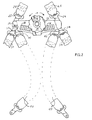
- the harness restraint system of the present invention which includes a single-point release mechanism 10 located in the center of the body and immediately below the rib cage. As shown herein, the occupant is restrained in the upper body by shoulder restraint straps 20 and 25, which can be secured to a vehicle, or, in the case of a high performance aircraft, to an ejection seat.
- the shoulder harness straps extend diagonally across the occupant's body and are terminated in latch plates 21 and 26 so that the straps cross approximately in the middle of the wearer's chest, at point "x".
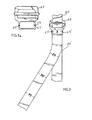
- the gross adjustment feature of the present invention including a sliding hasp 22, 27, which are secured at their upper ends to the shoulder harness straps 20 and 25.
- Shoulder harness straps 20 and 25 can be secured to an ejection seat in a high performance aircraft, which can.- also include a powered retractable harness mechanism.
- the lower end of each of the sliding hasps as shown in Fig. 1 are configured with a viewing window 23, 28 through which the indicator portion of the harness belt is received and can be adjusted in-accordance with the percentile corresponding to the occupant's body size.
- the lower part of the shoulder harness belts 20' and 25' are adjusted to the appropriate percentile indicator corresponding to the occupant's body size and weight before entering the harness system so that upon latching the latch plates 21 and 26 into the respective connection pins in the single-point release mechanism, the harness system substantially approximates the occupant's size.
- the occupant can then make minor adjustments by use of retractor adjustment assemblies 24 and 29.
- FIGs. 3 and 3a the gross adjustment feature is shown in an enlargement wherein the indicator harness belt 20' is slidably engaged in hasp 22 so that the indicator marks, which have been placed thereon according to the restraint system involved, can be viewed through the window 23, and aligned with indicator marks 23'.
- the harness assembly also includes lower body restraint belts 30 and 35 which can also include restraint adjustor assemblies 31 and 36.
- An anti-gravity strap 40 is shown as extending between the legs of the occupant, and sling support straps 32 and 37 are shown around the wearer's legs so that the lower portion of the wearer's body is supported at the.end of a parachute harness.
- These lower body restraint straps are terminated in latch plates 33 and 38 which can be connected to the single-point release device 10, while the anti-gravity strap 40 can be permanently connected to the device through elongated slot 11 in the release mechanism.
- FIGs. 2 an alternative embodiment of the present invention is shown in which all of the elements shown in Figs. 1 and la have been indicated with the same numerals, and alternative lower body anti-G/harness straps 40 and 45 are shown in phantom. These restraint straps are terminated in latching plates 41 and 46 which, in turn, can be connected to the single-point release device 10.
- the anti-gravity strap 34 has been eliminated, and the function has been replaced by the diverging leg straps 40 and 45.
- a single-point release device having a housing 12 on which is mounted for rotation a knob 14, which, can be turned upon depression of the release button 16.
- the distance between the two upper connection points in which latch plates 21 and 26 are inserted can be at least 100 mm (4 inches), but is preferably about 190 mm (7 1/2 inches), the release knob 14 being centered in the middle of the device.
- the lower connection points are preferably located directly opposite the upper connection points for convenience of operation and construction.
- the single-point release mechanisms also include fluid screens 18 which permit penetration of fluids such as water through the housing 12.
- fluids such as water through the housing 12.
- This type of mechanism allows an occupant such as a pilot to release himself from the flight harness when required.
- emergency conditions such as an aircraft fire or sea ditching
- the pilot needs to get out as quickly as possible.
- the violent motions incurred during escape including flailing of the arms and legs, must not accidently cause release.
- This factor necessitates the safety latch with a rotary motion.
- -A pull or push mechanism could accidently be released, but accidental imparting the rotary motion to the present device is highly unlikely in the absence of a conscious effort to release the mechanism.
- the single-point release of the present invention does not relate in any way to loads on the harness system itself.
- connection pins such as 19 (shown in cutaway of Figs. la and 2), by wedging the connection pins out of the latch plate holes.
- the force required is easily provided by a pilot, who can release at any time by pressing the release button 16 and rotating the central knob 14 in either direction using either hand. In a preferred embodiment the rotation pulls all four connection pins down simultaneously.
- the device can be provided with springs which then eject the latch plates in an outward direction and the harness is thereby released.
- Automatic actuation can be accomplished by a pyrotechnic device which is detonated by sensing a water environment. These devices are well known safety features in high performance aircraft technology. Immersion in water will cause them to fire, actuating a releasing mechanism to retract latch pins and jam the release mechanisms in the open position. If the latch plates are spring-loaded they will then be kicked free by the spring when the entire redundant system is fired. It is important for purposes of use and manufacture that the weight and size of the single-point release device be kept to a minimum, while it is also necessary to provide cross-over strap configuration, thus preferably placing the shoulder strap latch plates about 190 mm (7 1/2 inches) apart.
- a single-point release mechanism can be constructed of light weight material, such as plastic for non-loadbearing parts, which is 228 mm (9 inches) wide by about 95 mm (3 3/4 inches) wide and has a thickness of under about 19 mm (3/4 inch).
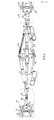
- Fig. 4 shows the overall single-point release mechanism without the full extensions of linking bars or rods.
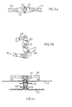
- Figs. 4a-c show different components of the mechanism shown in Fig. 4. Specifically, Figs. 4 and 4a show a crank arm 50 which is pinned by axle pin 51 to the axle 15 of knob 14. See Fig. 4a. Thus when knob 14 is rotated in either direction, crank arm 50 is made to rotate to the same extent.
- Crank arm 50 is connected at either end to couplings 52 and 54 which extend between the ends of crank arm 50 and the laterally-separated connection pins mounted in the housing at either end of the couplings 52 and 54.
- couplings 52 and 54 are both moved away from the connection pins located at the far ends thereof. The effect of this move away from the connection pins will be discussed in detail below.
- An emergency release mechanism is also shown in Figs. 4, 4b, and 6, which includes an emergency crank arm 60 connected at either end to emergency couplings 62 and 64 which, in turn, extend toward the laterally-spaced connection pins.
- the emergency crank arm 60 which is mounted for free rotation to the knob axle 15 is attached to a tension spring 65 at one end thereof for continual biasing in the direction of the spring.
- the opposite end of the crank arm 60 is fixed to a tie bar 68 which extends between two emergency actuator devices 70 and 75.
- the emergency actuator devices 70 and 75 should be mounted in the housing directly behind screens 18 so that they can be immersed in a water environment upon passage of water through the screen.
- FIG. 6 shows a detailed assembly of an example of a ballistic device which can be connected to the tie bar 68 via press fit head 71.
- the apparatus senses a water environment and detonates, the explosion causes projectile 72 to strike the press fit head 71 which detaches from the shell 73 thereby releasing tie bar 68. Redundancy in this emergency apparatus is preferred in order to preclude inadvertent detonation of the device.
- Figs. 4 and 5 show the relationship of the single-point release mechanism with the laterally spaced connection pins 19 as well as the pin retracting mechanism.
- connection pin 19 there is shown a pin base 80 on which a sliding latch bolt 81 is mounted for longitudinal movement, the latch bolt 81 being biased toward the extended position by compression spring 82.
- the compression spring 82 can be redundant.
- the latching bolt 81 is beveled at the operative end so that the lower part of the beveled surface 83 is oriented toward the aperture. In this way, the latching plate will strike the beveled surface 83 of the latching bolt and cam it downward against the action of compression spring 82 until the hole of the latching plate comes directly over the latching bolt at which point the latching bolt 81 returns under force of compression spring 82 to the extended position thereby engaging the latching plate with the shoulder 84.
- a retraction link 90 is provided which can in one embodiment be bifurcated as shown in Fig. 4.
- the link is mounted to the front wall of the housing 12 by a mounting bolt 91 which is attached to a slot 92 to permit longitudinal movement of the link 90 between the fully extended position shown in Figs. 4 and 5 and the retracting position, not shown in the Figures.
- the link is spring mounted by a compression spring 93 to ensure that inadvertent retraction of the pin does not occur.
- the retracting link 90 is always biased in the fully extended position shown in the Figures so that the latching bolt 81 is never retracted during non-actuated times.
- the spring loaded link 90 is connected at the interior end to coupling 52 and, in one preferred embodiment, to emergency coupling 62.
- the link 90 is pulled inward or towards the right in Fig. 5. This motion causes the link 90 to act upon the latching bolt 81 to retract it from the fully ,. extended position and permit removal of latching plates therefrom.
- link 90 is further provided with extension finger or fingers 95, each of which has a wedge shape so that the bottom portion thereof cams against the pin 85 located on latching bolt 81 to drive the bolt downward against the action of compression spring 82.
- the mechanism can manually be operated to retract the latching pin 81 in the downward position thereby releasing latch plates, and then allowed to return by turning the control knob 14 back to the neutral position in which crank arm 50 is in the laterally extended position shown in Figs. 4 and 5.
- the release mechanisms can also be provided with a shim 100 mounted on the housing in order to guide the wedge-shaped fingers 95. As can be seen from the drawings, release is accomplished by wedging the latch bolts out of the latch plates, the force being easily provided by the. occupant and/or the emergency release system.
- couplings 52 and 54 In order to permit free travel of the link 90 to the disconnect position in the emergency operation, couplings 52 and 54 must also be equipped with a longitudinal free travel feature, which is shown in the drawings as elongated slots 53 and 55.
- the mechanism provided in the present invention provides a highly dependable single-point release device which is convenient and has a safe emergency release feature, and thus, while there have been described what are presently believed to be the preferred embodiments of the invention, those skilled in the art will realize that changes and modifications may be made thereto without departing from the spirit of the invention, and it is intended to claim all such changes and modifications as fall within the true scope of the invention.
Landscapes
- Business, Economics & Management (AREA)
- Emergency Management (AREA)
- Engineering & Computer Science (AREA)
- Aviation & Aerospace Engineering (AREA)
- Emergency Lowering Means (AREA)
- Seats For Vehicles (AREA)
- Automotive Seat Belt Assembly (AREA)
Applications Claiming Priority (2)
| Application Number | Priority Date | Filing Date | Title |
|---|---|---|---|
| US736796 | 1985-05-22 | ||
| US06/736,796 US4738413A (en) | 1985-05-22 | 1985-05-22 | Harness restraint system |
Publications (2)
| Publication Number | Publication Date |
|---|---|
| EP0203451A2 true EP0203451A2 (de) | 1986-12-03 |
| EP0203451A3 EP0203451A3 (de) | 1987-10-21 |
Family
ID=24961336
Family Applications (1)
| Application Number | Title | Priority Date | Filing Date |
|---|---|---|---|
| EP86106517A Withdrawn EP0203451A3 (de) | 1985-05-22 | 1986-05-14 | Gurtrückhaltevorrichtung |
Country Status (5)
| Country | Link |
|---|---|
| US (1) | US4738413A (de) |
| EP (1) | EP0203451A3 (de) |
| JP (1) | JPS61271154A (de) |
| CA (1) | CA1273614C (de) |
| IL (1) | IL78852A0 (de) |
Cited By (2)
| Publication number | Priority date | Publication date | Assignee | Title |
|---|---|---|---|---|
| ITMO20130278A1 (it) * | 2013-10-02 | 2015-04-03 | Ambitalia S P A | Cintura di sicurezza per il trattenimento di operatori a bordo di veicoli, giubbotto integrante la detta cintura e assieme giubbotto-sedile associato |
| CN107985247A (zh) * | 2017-12-08 | 2018-05-04 | 佛山市海科云筹信息技术有限公司 | 安全带 |
Families Citing this family (49)
| Publication number | Priority date | Publication date | Assignee | Title |
|---|---|---|---|---|
| US5220976A (en) * | 1991-04-08 | 1993-06-22 | Gunter Larry W | Safety harness |
| US5265910A (en) * | 1992-02-26 | 1993-11-30 | Buckle Buddy Corporation | Vehicle seat belt shoulder strap adjusting device |
| US5306044A (en) * | 1992-03-11 | 1994-04-26 | Tucker Curt L | Body restraint system |
| US5277348A (en) * | 1992-06-02 | 1994-01-11 | Reid Sandy R | Articulated parachute harness |
| US5562326A (en) * | 1994-06-21 | 1996-10-08 | Stroud; Robert W. | Personal body restraint device |
| USD367245S (en) | 1994-06-30 | 1996-02-20 | Triplett Ivowen R | 5 way seat belt |
| USD376872S (en) | 1995-08-16 | 1996-12-24 | Stroud Robert W | Seat restraint |
| US20040113412A1 (en) * | 1997-11-11 | 2004-06-17 | Go Giok Djien | Multi-point seat belt |
| US6049954A (en) * | 1998-05-19 | 2000-04-18 | The First Years, Inc. | Safety buckle |
| US6123166A (en) * | 1998-08-28 | 2000-09-26 | Trw Vehicle Safety Systems Inc. | Release apparatus for a seat belt buckle |
| US6390561B1 (en) | 2000-03-27 | 2002-05-21 | Joshua Oghenogieme Osime | Adaptable rider restraint system |
| US6820902B2 (en) * | 2000-09-29 | 2004-11-23 | Hyun S. Kim | Supplemental restraint system |
| US6902193B2 (en) | 2000-09-29 | 2005-06-07 | Hoon Y. Kim | Supplemental restraint system |
| GB2390063B (en) * | 2001-03-28 | 2004-03-10 | Martin Baker Aircraft Co Ltd | Improvements in or relating to harnesses and inertia reels |
| DE10143654C1 (de) * | 2001-09-05 | 2003-06-12 | Schroth Safety Products Gmbh | Hosenträgergurt |
| US6637377B2 (en) | 2002-02-13 | 2003-10-28 | Bos Automotive Products, Inc. | Animal restraint system for vehicles |
| JP3754015B2 (ja) * | 2002-10-10 | 2006-03-08 | 本田技研工業株式会社 | 自動車用シートベルト装置 |
| US7000994B2 (en) * | 2003-05-05 | 2006-02-21 | Cassee Leighton | Vehicle seat assembly |
| US7607697B2 (en) * | 2003-06-18 | 2009-10-27 | Indiana Mills & Manufacturing, Inc. | Load control device |
| US7073627B2 (en) * | 2003-09-05 | 2006-07-11 | D B Industries, Inc. | Dorsal pad assembly for use with a safety harness |
| EP1660192B1 (de) * | 2003-09-05 | 2015-11-04 | D B Industries, LLC | Rückenwirbelkissenanordnung für den einsatz bei einem sicherheitsgurtzeug |
| US7210707B2 (en) * | 2003-09-18 | 2007-05-01 | Schroth Safety Products Gmbh | Belt assembly |
| US7201399B2 (en) * | 2003-10-07 | 2007-04-10 | Trw Vehicle Safety Systems Inc. | Four-point seat belt system with buckle-lowering belts |
| ZA200705958B (en) * | 2006-07-18 | 2008-08-27 | Global Seating Systems Llc | Seat assembly with removable portions to accommodate occupant-worn equipment |
| US8132864B2 (en) * | 2006-07-20 | 2012-03-13 | Blackmon Michael M | Child safety seat with emergency harness release |
| EP1918163B1 (de) * | 2006-10-30 | 2009-12-16 | Key Safety Systems, Inc. | Kindersicherheitsrückhaltevorrichtung |
| PL211795B1 (pl) * | 2006-11-10 | 2012-06-29 | Kujawski Edward Ramatti | System taśm przytrzymujących, w szczególności przeznaczony do stosowania w urządzeniach służących do przewozu dzieci w pojazdach |
| US7905553B2 (en) * | 2007-04-05 | 2011-03-15 | Elaine Lichtner | Safety garment and method of using the same |
| US7815255B1 (en) * | 2008-07-18 | 2010-10-19 | The United States Of America As Represented By The Secretary Of The Army | Seat for combat vehicle |
| US8011730B2 (en) | 2008-10-06 | 2011-09-06 | Black Mountain Industries, Inc. | Soldier platform system |
| US8657247B2 (en) | 2008-10-06 | 2014-02-25 | Black Mountain Industries, Inc. | Ratchet platform |
| US8132838B2 (en) * | 2008-10-06 | 2012-03-13 | Black Mountain Industries, Inc. | Soldier support system in a vehicle |
| US8590853B2 (en) * | 2008-10-06 | 2013-11-26 | Black Mountain Industries, Inc. | Ratchet platform |
| US8757721B2 (en) | 2008-10-06 | 2014-06-24 | Black Mountain Industries, Inc. | Soldier platform system |
| US8919882B2 (en) | 2008-10-06 | 2014-12-30 | Black Mountain Industries, Inc. | Soldier platform system |
| US8998286B2 (en) | 2008-10-06 | 2015-04-07 | Black Mountain Industries, Inc. | Soldier support system in a vehicle |
| US7941902B1 (en) | 2010-06-10 | 2011-05-17 | Julien Edwin Roy | Safety belt release mechanism |
| US8127409B2 (en) | 2010-06-10 | 2012-03-06 | Julien Edwin Roy | Safety belt release mechanism |
| WO2013188614A1 (en) * | 2012-06-13 | 2013-12-19 | Indiana Mills & Manufacturing Inc | Integral multi-point restraint system for vehicle seat |
| USD708880S1 (en) * | 2013-06-10 | 2014-07-15 | Angela Michelle Howard | Backrest for a motorized lift chair |
| US8925669B1 (en) * | 2013-08-22 | 2015-01-06 | Marline Augustin Saint-Hilaire | Motorcycle safety belt device |
| US9067561B2 (en) * | 2013-11-04 | 2015-06-30 | Shawn Crews | Vehicle seat harness anchoring system |
| US9808369B1 (en) * | 2014-10-21 | 2017-11-07 | Medical Specialties, Incorporated | Adjustable orthopedic back support |
| TWI636906B (zh) * | 2017-08-31 | 2018-10-01 | 王亮雄 | 多點式安全帶裝置 |
| US10596929B2 (en) * | 2017-09-22 | 2020-03-24 | Jodi L. Houin | Child restraint system including harness and adjustment mechanism |
| CN107985246A (zh) * | 2017-12-08 | 2018-05-04 | 佛山市海科云筹信息技术有限公司 | 安全带 |
| CN107914662A (zh) * | 2017-12-08 | 2018-04-17 | 佛山市海科云筹信息技术有限公司 | 安全带 |
| CN107985248A (zh) * | 2017-12-08 | 2018-05-04 | 佛山市海科云筹信息技术有限公司 | 安全带 |
| SG10201907758XA (en) * | 2019-08-22 | 2021-03-30 | Green 5 Holding Pte Ltd | A self-releasable safety belt |
Family Cites Families (11)
| Publication number | Priority date | Publication date | Assignee | Title |
|---|---|---|---|---|
| FR566680A (fr) * | 1923-05-25 | 1924-02-18 | Perfectionnement apporté aux ceintures de pilotes d'avions | |
| US2195334A (en) * | 1938-06-21 | 1940-03-26 | Mills Equipment Co Ltd | Safety apparatus for retaining persons in the seats of aircraft or other vehicles |
| GB738989A (en) * | 1952-12-24 | 1955-10-26 | Frank Bernard Harley | Improvements relating to buckles |
| GB915168A (en) * | 1960-07-08 | 1963-01-09 | Harley Patents Int | Improvements relating to releasable connectors |
| US3424134A (en) * | 1966-12-12 | 1969-01-28 | Irvin Industries Inc | Industrial safety harness |
| GB1187677A (en) * | 1967-09-22 | 1970-04-15 | Mini Of Technology London | Improvements in or relating to Seat Harnesses |
| US3521333A (en) * | 1968-05-08 | 1970-07-21 | Aerolex Products Ltd | Releasable fasteners |
| US3692262A (en) * | 1970-12-11 | 1972-09-19 | Koch & Sons Inc H | Parachute harness and single point release |
| US4302049A (en) * | 1979-04-27 | 1981-11-24 | Simpson Elwood J B | Harness release assembly |
| US4231616A (en) * | 1979-08-17 | 1980-11-04 | The Boeing Company | Combined shoulder harness and lap belt restraint apparatus having single fasten/release point at lap buckle |
| US4488691A (en) * | 1982-12-27 | 1984-12-18 | The United States Of America As Represented By The Secretary Of The Navy | Torso restraint system |
-
1985
- 1985-05-22 US US06/736,796 patent/US4738413A/en not_active Expired - Lifetime
-
1986
- 1986-05-06 CA CA508485A patent/CA1273614C/en not_active Expired
- 1986-05-14 EP EP86106517A patent/EP0203451A3/de not_active Withdrawn
- 1986-05-20 IL IL78852A patent/IL78852A0/xx unknown
- 1986-05-22 JP JP61118365A patent/JPS61271154A/ja active Pending
Cited By (2)
| Publication number | Priority date | Publication date | Assignee | Title |
|---|---|---|---|---|
| ITMO20130278A1 (it) * | 2013-10-02 | 2015-04-03 | Ambitalia S P A | Cintura di sicurezza per il trattenimento di operatori a bordo di veicoli, giubbotto integrante la detta cintura e assieme giubbotto-sedile associato |
| CN107985247A (zh) * | 2017-12-08 | 2018-05-04 | 佛山市海科云筹信息技术有限公司 | 安全带 |
Also Published As
| Publication number | Publication date |
|---|---|
| JPS61271154A (ja) | 1986-12-01 |
| EP0203451A3 (de) | 1987-10-21 |
| IL78852A0 (en) | 1986-09-30 |
| US4738413A (en) | 1988-04-19 |
| CA1273614A (en) | 1990-09-04 |
| CA1273614C (en) | 1990-09-04 |
Similar Documents
| Publication | Publication Date | Title |
|---|---|---|
| US4738413A (en) | Harness restraint system | |
| US3146846A (en) | Seat belt buckle | |
| US4437628A (en) | Position and restraint system for aircrewman | |
| US2763451A (en) | Apparatus for releasing an aviator from a safety harness connection with a seat | |
| US5176342A (en) | Goggles emergency release apparatus | |
| US3404439A (en) | Fastener for use on parachute harnesses | |
| US5857247A (en) | Buckle system for manual or automatic release of crew member harness from parachute | |
| EP0089172A2 (de) | Ausklinkbare Verbindung | |
| US2634802A (en) | Shoulder harness for vehicle occupants | |
| WO2013009638A1 (en) | Restraint system with dual release mechanisms | |
| US4589172A (en) | Central belt lock, particularly for a parachute harness | |
| US2970796A (en) | Quick release mechanism | |
| GB2083543A (en) | Strap fastener | |
| US2689697A (en) | Safety belt release | |
| US12337967B2 (en) | Aerial delivery system | |
| EP4147905B1 (de) | Hilfserinnerungsvorrichtung zur gangeinstellung eines kindersicherheitssitzes | |
| US3013743A (en) | Inter-aircraft attaching mechanism | |
| US3214118A (en) | Aircraft ejection seats | |
| US5205665A (en) | Fitting release utilizing bolt action | |
| US3633852A (en) | Aircraft seat ejection safety system | |
| USRE23981E (en) | stanley | |
| EP3707033B1 (de) | Notfallvorrichtung zur schnellen freisetzung von sicherheitsgurten für fahrzeuge | |
| EP3496976B1 (de) | Sicherheitsgurtsystem mit taktischer ganganpassung und verfahren | |
| US4428551A (en) | Tow plate for aerial cargo delivery | |
| EP3307106B1 (de) | Schnallenlösemechanismus |
Legal Events
| Date | Code | Title | Description |
|---|---|---|---|
| PUAI | Public reference made under article 153(3) epc to a published international application that has entered the european phase |
Free format text: ORIGINAL CODE: 0009012 |
|
| AK | Designated contracting states |
Kind code of ref document: A2 Designated state(s): AT BE CH DE FR GB IT LI LU NL SE |
|
| RIN1 | Information on inventor provided before grant (corrected) |
Inventor name: KNOLL, FRANK Inventor name: SPINOSA, DOMINIC J. |
|
| PUAL | Search report despatched |
Free format text: ORIGINAL CODE: 0009013 |
|
| AK | Designated contracting states |
Kind code of ref document: A3 Designated state(s): AT BE CH DE FR GB IT LI LU NL SE |
|
| 17P | Request for examination filed |
Effective date: 19880414 |
|
| 17Q | First examination report despatched |
Effective date: 19881024 |
|
| STAA | Information on the status of an ep patent application or granted ep patent |
Free format text: STATUS: THE APPLICATION IS DEEMED TO BE WITHDRAWN |
|
| 18D | Application deemed to be withdrawn |
Effective date: 19900307 |
|
| RIN1 | Information on inventor provided before grant (corrected) |
Inventor name: SPINOSA, DOMINIC J. Inventor name: KNOLL, FRANK |