EP0203497B1 - Enveloppe tubulaire divisée longitudinalement, en particulier manchon de câble, en matériau rétractable - Google Patents
Enveloppe tubulaire divisée longitudinalement, en particulier manchon de câble, en matériau rétractable Download PDFInfo
- Publication number
- EP0203497B1 EP0203497B1 EP86106835A EP86106835A EP0203497B1 EP 0203497 B1 EP0203497 B1 EP 0203497B1 EP 86106835 A EP86106835 A EP 86106835A EP 86106835 A EP86106835 A EP 86106835A EP 0203497 B1 EP0203497 B1 EP 0203497B1
- Authority
- EP
- European Patent Office
- Prior art keywords
- longitudinal edge
- tubular envelope
- split tubular
- longitudinally split
- bracket
- Prior art date
- Legal status (The legal status is an assumption and is not a legal conclusion. Google has not performed a legal analysis and makes no representation as to the accuracy of the status listed.)
- Expired - Lifetime
Links
- 239000000463 material Substances 0.000 title claims abstract description 6
- 239000011324 bead Substances 0.000 claims abstract description 11
- 230000015572 biosynthetic process Effects 0.000 claims description 19
- 238000000034 method Methods 0.000 claims description 7
- 239000002313 adhesive film Substances 0.000 claims description 6
- 239000011248 coating agent Substances 0.000 claims description 4
- 238000000576 coating method Methods 0.000 claims description 4
- 238000007789 sealing Methods 0.000 claims description 3
- 229910000639 Spring steel Inorganic materials 0.000 claims description 2
- 238000004132 cross linking Methods 0.000 claims description 2
- 239000003365 glass fiber Substances 0.000 claims description 2
- 239000002184 metal Substances 0.000 claims description 2
- 239000000853 adhesive Substances 0.000 claims 2
- 230000001070 adhesive effect Effects 0.000 claims 2
- 230000004927 fusion Effects 0.000 claims 2
- 238000003780 insertion Methods 0.000 claims 1
- 230000037431 insertion Effects 0.000 claims 1
- 229920001169 thermoplastic Polymers 0.000 claims 1
- 239000004416 thermosoftening plastic Substances 0.000 claims 1
- 230000007704 transition Effects 0.000 claims 1
- 239000002654 heat shrinkable material Substances 0.000 abstract 1
- 239000000565 sealant Substances 0.000 description 5
- 239000004831 Hot glue Substances 0.000 description 4
- 230000006978 adaptation Effects 0.000 description 2
- 238000003860 storage Methods 0.000 description 2
- 230000006835 compression Effects 0.000 description 1
- 238000007906 compression Methods 0.000 description 1
- 230000000694 effects Effects 0.000 description 1
- 239000013013 elastic material Substances 0.000 description 1
- 238000009434 installation Methods 0.000 description 1
- 238000004519 manufacturing process Methods 0.000 description 1
- 238000000465 moulding Methods 0.000 description 1
- 230000002787 reinforcement Effects 0.000 description 1
- 238000007493 shaping process Methods 0.000 description 1
- 229920001187 thermosetting polymer Polymers 0.000 description 1
- 230000008719 thickening Effects 0.000 description 1
Images

Classifications
-
- B—PERFORMING OPERATIONS; TRANSPORTING
- B29—WORKING OF PLASTICS; WORKING OF SUBSTANCES IN A PLASTIC STATE IN GENERAL
- B29C—SHAPING OR JOINING OF PLASTICS; SHAPING OF MATERIAL IN A PLASTIC STATE, NOT OTHERWISE PROVIDED FOR; AFTER-TREATMENT OF THE SHAPED PRODUCTS, e.g. REPAIRING
- B29C61/00—Shaping by liberation of internal stresses; Making preforms having internal stresses; Apparatus therefor
- B29C61/06—Making preforms having internal stresses, e.g. plastic memory
- B29C61/10—Making preforms having internal stresses, e.g. plastic memory by bending plates or sheets
-
- F—MECHANICAL ENGINEERING; LIGHTING; HEATING; WEAPONS; BLASTING
- F16—ENGINEERING ELEMENTS AND UNITS; GENERAL MEASURES FOR PRODUCING AND MAINTAINING EFFECTIVE FUNCTIONING OF MACHINES OR INSTALLATIONS; THERMAL INSULATION IN GENERAL
- F16L—PIPES; JOINTS OR FITTINGS FOR PIPES; SUPPORTS FOR PIPES, CABLES OR PROTECTIVE TUBING; MEANS FOR THERMAL INSULATION IN GENERAL
- F16L57/00—Protection of pipes or objects of similar shape against external or internal damage or wear
-
- H—ELECTRICITY
- H02—GENERATION; CONVERSION OR DISTRIBUTION OF ELECTRIC POWER
- H02G—INSTALLATION OF ELECTRIC CABLES OR LINES, OR OF COMBINED OPTICAL AND ELECTRIC CABLES OR LINES
- H02G15/00—Cable fittings
- H02G15/08—Cable junctions
- H02G15/18—Cable junctions protected by sleeves, e.g. for communication cable
- H02G15/1806—Heat shrinkable sleeves
- H02G15/1813—Wraparound or slotted sleeves
-
- Y—GENERAL TAGGING OF NEW TECHNOLOGICAL DEVELOPMENTS; GENERAL TAGGING OF CROSS-SECTIONAL TECHNOLOGIES SPANNING OVER SEVERAL SECTIONS OF THE IPC; TECHNICAL SUBJECTS COVERED BY FORMER USPC CROSS-REFERENCE ART COLLECTIONS [XRACs] AND DIGESTS
- Y10—TECHNICAL SUBJECTS COVERED BY FORMER USPC
- Y10S—TECHNICAL SUBJECTS COVERED BY FORMER USPC CROSS-REFERENCE ART COLLECTIONS [XRACs] AND DIGESTS
- Y10S174/00—Electricity: conductors and insulators
- Y10S174/08—Shrinkable tubes
-
- Y—GENERAL TAGGING OF NEW TECHNOLOGICAL DEVELOPMENTS; GENERAL TAGGING OF CROSS-SECTIONAL TECHNOLOGIES SPANNING OVER SEVERAL SECTIONS OF THE IPC; TECHNICAL SUBJECTS COVERED BY FORMER USPC CROSS-REFERENCE ART COLLECTIONS [XRACs] AND DIGESTS
- Y10—TECHNICAL SUBJECTS COVERED BY FORMER USPC
- Y10S—TECHNICAL SUBJECTS COVERED BY FORMER USPC CROSS-REFERENCE ART COLLECTIONS [XRACs] AND DIGESTS
- Y10S428/00—Stock material or miscellaneous articles
- Y10S428/91—Product with molecular orientation
-
- Y—GENERAL TAGGING OF NEW TECHNOLOGICAL DEVELOPMENTS; GENERAL TAGGING OF CROSS-SECTIONAL TECHNOLOGIES SPANNING OVER SEVERAL SECTIONS OF THE IPC; TECHNICAL SUBJECTS COVERED BY FORMER USPC CROSS-REFERENCE ART COLLECTIONS [XRACs] AND DIGESTS
- Y10—TECHNICAL SUBJECTS COVERED BY FORMER USPC
- Y10S—TECHNICAL SUBJECTS COVERED BY FORMER USPC CROSS-REFERENCE ART COLLECTIONS [XRACs] AND DIGESTS
- Y10S428/00—Stock material or miscellaneous articles
- Y10S428/913—Material designed to be responsive to temperature, light, moisture
-
- Y—GENERAL TAGGING OF NEW TECHNOLOGICAL DEVELOPMENTS; GENERAL TAGGING OF CROSS-SECTIONAL TECHNOLOGIES SPANNING OVER SEVERAL SECTIONS OF THE IPC; TECHNICAL SUBJECTS COVERED BY FORMER USPC CROSS-REFERENCE ART COLLECTIONS [XRACs] AND DIGESTS
- Y10—TECHNICAL SUBJECTS COVERED BY FORMER USPC
- Y10T—TECHNICAL SUBJECTS COVERED BY FORMER US CLASSIFICATION
- Y10T428/00—Stock material or miscellaneous articles
- Y10T428/13—Hollow or container type article [e.g., tube, vase, etc.]
- Y10T428/1328—Shrinkable or shrunk [e.g., due to heat, solvent, volatile agent, restraint removal, etc.]
-
- Y—GENERAL TAGGING OF NEW TECHNOLOGICAL DEVELOPMENTS; GENERAL TAGGING OF CROSS-SECTIONAL TECHNOLOGIES SPANNING OVER SEVERAL SECTIONS OF THE IPC; TECHNICAL SUBJECTS COVERED BY FORMER USPC CROSS-REFERENCE ART COLLECTIONS [XRACs] AND DIGESTS
- Y10—TECHNICAL SUBJECTS COVERED BY FORMER USPC
- Y10T—TECHNICAL SUBJECTS COVERED BY FORMER US CLASSIFICATION
- Y10T428/00—Stock material or miscellaneous articles
- Y10T428/24—Structurally defined web or sheet [e.g., overall dimension, etc.]
- Y10T428/24008—Structurally defined web or sheet [e.g., overall dimension, etc.] including fastener for attaching to external surface
-
- Y—GENERAL TAGGING OF NEW TECHNOLOGICAL DEVELOPMENTS; GENERAL TAGGING OF CROSS-SECTIONAL TECHNOLOGIES SPANNING OVER SEVERAL SECTIONS OF THE IPC; TECHNICAL SUBJECTS COVERED BY FORMER USPC CROSS-REFERENCE ART COLLECTIONS [XRACs] AND DIGESTS
- Y10—TECHNICAL SUBJECTS COVERED BY FORMER USPC
- Y10T—TECHNICAL SUBJECTS COVERED BY FORMER US CLASSIFICATION
- Y10T428/00—Stock material or miscellaneous articles
- Y10T428/24—Structurally defined web or sheet [e.g., overall dimension, etc.]
- Y10T428/2419—Fold at edge
- Y10T428/24198—Channel-shaped edge component [e.g., binding, etc.]
-
- Y—GENERAL TAGGING OF NEW TECHNOLOGICAL DEVELOPMENTS; GENERAL TAGGING OF CROSS-SECTIONAL TECHNOLOGIES SPANNING OVER SEVERAL SECTIONS OF THE IPC; TECHNICAL SUBJECTS COVERED BY FORMER USPC CROSS-REFERENCE ART COLLECTIONS [XRACs] AND DIGESTS
- Y10—TECHNICAL SUBJECTS COVERED BY FORMER USPC
- Y10T—TECHNICAL SUBJECTS COVERED BY FORMER US CLASSIFICATION
- Y10T428/00—Stock material or miscellaneous articles
- Y10T428/24—Structurally defined web or sheet [e.g., overall dimension, etc.]
- Y10T428/24777—Edge feature
Definitions
- the invention relates to a longitudinally divided, tubular sheath, in particular a cable sleeve, made of shrinkable material with a clamping closure device along the longitudinal edges, consisting of a continuous, protruding formation, which is surrounded by a longitudinal, approximately U-shaped bracket.
- a long tubular envelope which consists of shrinkable material and has a clamping closure device along its longitudinal edges.
- This closure device consists of a shape which is designed as a divided bead, these partial beads being held together by an approximately U-shaped clamp in the closed state. These partial beads are located along each longitudinal edge, so that the dividing line runs between the partial beads in the closed state.
- a longitudinally divided tubular sheath or cable sleeve made of shrinkable material with a clamping closure device along the longitudinal edges is known.
- One of the longitudinal edges is provided with a protruding shape and the other longitudinal edge is provided with a grid-shaped groove, the shape and groove being designed such that they can be latched into one another.
- a clamp is also used for fixation, which surrounds the grid-shaped groove on the outside and presses it together at the narrow point. A pre-adjustment is not possible because the locking parts are firmly attached to both longitudinal edges.
- the object is now achieved with a longitudinally divided tubular casing of the type described above in that the formation on the first longitudinal edge is arranged laterally projecting, that the second longitudinal edge is profiled and so flexible that it conforms to the profile of the formation of the first longitudinal edge is that the clip has an internal profile adapted to the shape and longitudinally extending cams on the inner surfaces of each leg as raster patterns, that in the case of cams running parallel in one leg, the distance between the opposing cams closest to the longitudinal opening of the clip is greater than the distance from the inside subsequent cams, the opening being dimensioned so that it with at least one Grid can be slid over the molded-on second longitudinal edge and the head part of the clip and the rear part of the first longitudinal edge are designed as guide surfaces for a closing tool.
- this is achieved by that only one shape is arranged along one longitudinal edge of the casing and the second longitudinal edge is without a profile, so that it can be fixed as required, that is to say depending on the required length of the shrinkable middle part.
- This pre-adaptation to the sheathing diameter is carried out by the shaping of the profile-free longitudinal edge to the protruding shape of the first longitudinal edge and finally by the fixation with the aid of a U-shaped clamp, which is pushed onto the profile-free second longitudinal edge molded onto the shape of the first longitudinal edge.
- This fixation by the clip can take place in several grids, the final jamming taking place during the shrinkage, since the increase in the wall of the molded longitudinal edge during the shrinkage causes an additional jamming in the closure area between the clip and the molding.
- Appropriate embeddings inside the cover ensure the required sealing effect and improve the adhesion to the covered object. With the help of a suitable tool with correspondingly adapted pressure surfaces, the fixation of the clamp can be made easier.
- FIG. 1 shows the longitudinally divided casing 1 according to the invention as it is assembled as a casing for any object.
- This sleeve 1 consists essentially of the shrinkable middle part 2, which is placed around the object to be wrapped, and of a longitudinally extending, laterally protruding formation 4-4a along the one longitudinal edge 3, via which the second profile-free longitudinal edge 7 of the sleeve 1 is formed and is fixed by a clamp 8.
- the formation 4-4a consists of a thickened end, an enlarged compared to the approach 4a extension 4, which is, for example, button-shaped, so that a kind of undercut is created in this way, in which the clip 8 is engaged.
- This formation 4-4a runs along the first longitudinal edge 3, which is reinforced compared to the central part 2 in order to ensure the required strength in the closure area. Furthermore, this reinforced longitudinal edge 3 has a retaining bead 5, which serves for the stretching process in the manufacture of the casing 1.
- the inner surfaces of the casing 1 have a heat-activatable sealant 6, for example a commercially available hot melt adhesive. In this case, this sealant 6 is applied as a coating.
- the clamp 8, which is pressed on as a rail along the formation 4-4a, has transverse slots 9 in its head part 8a, through which the flexibility in the longitudinal direction can be improved.
- the clip 8 has an inner profile which is adapted to the formation 4-4a and is dimensioned in the opening in such a way that it can be pressed open by clamping over the formation 4-4a occupied by the longitudinal edge 7 without profile.
- the reinforced one Longitudinal edge 3 with respect to the shrinkable middle part 2 of the casing 1 to a higher degree of crosslinking, so that it remains dimensionally stable when exposed to heat.
- the clip 8 can be made, for example, from metal, preferably from spring steel, or also from a thermoset, the latter advantageously being provided with a glass fiber reinforcement.
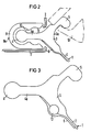
- FIG 2 the closure area of the shell 1 is now shown enlarged for clarity.
- the button-like enlargement 4 of the formation 4-4a which is arranged so as to protrude along the reinforced longitudinal edge 3, becomes particularly clear.
- the shrinkable middle part 2 and the profile-less second longitudinal edge 7 are shown in a broken-off manner in order to better illustrate the relationships between the bracket 8 and the formation 4-4a.
- the clip 8 shown here has in its legs two longitudinal cams 10 and 11, a longitudinal groove being formed between them, which is intended for a first, light grid during assembly.
- the clip 8 can now be pressed on relatively easily without aids and is therefore already pre-adjusted for the final engagement by means of a suitable tool.
- the head part 8a of the clamp 8 and the rear part 3a of the first longitudinal edge 3 are designed as guide surfaces for a closing tool, as shown in FIG. 4.
- the final and tight fixation of the closure area finally takes place during the shrinking process, since the regression of the shrinkable longitudinal edge 7 results in a thickening of the wall thickness, which leads to an additional "compression" of the longitudinal edge 7 between the Clip 8 and the formation 4-4a leads.
- the sealant on the inner surface of the casing 1 is in the form of a hot-melt adhesive coating 6 and is also placed around the shape (4-4a), so that a seal also takes place in the closure area.
- the reinforced longitudinal edge 3 has a retaining bead 5 at the upper end, which serves to attach a stretching tool 12 during expansion and which can be cut in the longitudinal direction as required.
- FIG. 3 shows an expanded exemplary embodiment in which an additional storage as an excess of hot-melt adhesive 13 is introduced in the closure area.
- this hot melt adhesive excess 13 is embedded in a kind of longitudinal groove in the longitudinal edge 3 and, like the inner coating 6, is activated by the action of heat during the shrinking process.
- an elastic material can also be incorporated, so that irregularities in the closure area can also be compensated for in this way.
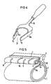
- FIG 4 the tool 14 is now shown, with the help of which the closure pre-fixed in a first grid can be brought into its final position.
- This tool has two tapered legs 15 and 16, which are designed as arcuate pressure surfaces 15a and 16a. These two legs 15 and 16 are drawn with their pressure surfaces 15a and 16a along the guide surfaces on the head part 8a of the bracket 8 and the rear part 3a of the longitudinal edge 3, whereby the bracket 8 is pressed into the final grid due to the conical legs. After this closing process, shrinking can begin.
- FIG. 5 shows an embodiment in which the sealant is introduced as a loosely separate adhesive film 6a.
- the adhesive film 6a can then be wrapped inwards again into the wrapping space, so that in this case the closure area between the formation 4-4a and the clip 8 is not glued.
- the clip 8 has slots 9 cut alternately from the edge to increase flexibility.
Landscapes
- Engineering & Computer Science (AREA)
- General Engineering & Computer Science (AREA)
- Mechanical Engineering (AREA)
- Cable Accessories (AREA)
- Clamps And Clips (AREA)
- Insulating Bodies (AREA)
- Protection Of Pipes Against Damage, Friction, And Corrosion (AREA)
- Ropes Or Cables (AREA)
- Details Of Indoor Wiring (AREA)
Claims (12)
- Gaine tubulaire souple (1), fendue longitudinalement, notamment manchon de câble, en un matériau rétractable, comprenant, le long des bords longitudinaux (3, 7), un dispositif de fermeture (4 à 8) par serrage, constitué d'une excroissance saillante (4 à 4a), continue, qui est entourée d'un crampon (8) sensiblement en forme de U et qui est disposée en saillie latéralement sur le premier bord longitudinal (3),
caractérisée,
en ce que le second bord longitudinal (7) ne présente pas de profil propre et est si souple qu'il peut épouser le profil de l'excroissance (4 à 4a) du premier bord longitudinal (3), en ce que le crampon (8) présente un profil intérieur adapté à l'excroissance (4, 4a) et, sur les surfaces intérieures de chaque branche, des cames saillantes (10, 11) s'étendant longitudinalement et servant de moyens d'encliquetage, en ce que, pour les cames (10, 11) s'étendant parallèlement dans une branche, la distance, entre les cames (11) mutuellement opposées les plus proches de l'ouverture longitudinale du crampon (8), est supérieure à la distance entre les cames suivantes et dirigées vers l'intérieur, l'ouverture ayant des dimensions telles qu'elle peut être enfilée avec serrage par au moins un moyen d'encliquetage (10, 11) sur le second bord longitudinal (7) issu de l'excroissance (4 à 4a), alors que la tête (8a) du crampon (8) et la partie arrière (3a) du premier bord longitudinal (3) sont constituées en surfaces de guidage d'un outil de fermeture. - Gaine tubulaire souple, fendue longitudinalement suivant la revendication 1,
caractérisée,
en ce que le premier bord longitudinal (3) est renforcé par rapport à la partie médiane (2) rétractable et étirée du manchon de câble (1). - Gaine tubulaire souple, fendue longitudinalement suivant l'une des revendications précédentes,
caractérisée,
en ce que le premier bord longitudinal (3) présente, par rapport à la partie médiane (2), un degré de réticulation plus élevé. - Gaine tubulaire souple, fendue longitudinalement suivant l'une des revendications précédentes,
caractérisée,
en ce que la paroi intérieure du manchon de câble (1) comporte un revêtement de colle fusible (6). - Gaine tubulaire souple, fendue longitudinalement suivant l'une des revendications 1 à 3,
caractérisée,
en ce qu'un ruban adhésif (6a), correspondant à la surface du manchon de câble (1), est disposé dans la partie intérieure du manchon de câble (1), ce ruban adhésif (6a) étant fixé le long du premier bord longitudinal (3) renforcé, au moins le long de l'arête (18). - Gaine tubulaire souple, fendue longitudinalement suivant l'une des revendications précédentes,
caractérisée,
en ce que le premier bord longitudinal (3) renforcé comporte un bourrelet de maintien (5). - Gaine tubulaire souple, fendue longitudinalement suivant l'une des revendications précédentes,
caractérisée,
en ce que l'excroissance (4 à 4a) présente, dans la partie élargie (4), une section transversale sensiblement circulaire, le diamètre étant plus grand que l'épaisseur de sa partie de raccordement (4a), de manière à former une contre-dépouille. - Gaine tubulaire souple, fendue longitudinalement suivant l'une des revendications précédentes,
caractérisée,
en ce que le crampon (8) est en métal, de préférence en acier pour ressort. - Gaine tubulaire souple, fendue longitudinalement suivant l'une des revendications 1 à 7,
caractérisée,
en ce que le crampon (8) est en une résine thermoplastique renforcée par de la fibre de verre. - Gaine tubulaire souple, fendue longitudinalement suivant l'une des revendications précédentes,
caractérisée,
en ce que la tête (8a) du crampon (8) comporte des fentes (9) transversalement à la direction longitudinale. - Gaine tubulaire souple, fendue longitudinalement suivant l'une des revendications précédentes,
caractérisée,
en ce que, dans la région de transition entre le bord longitudinal (3) renforcé et la partie médiane (2) étirée du manchon de câble (1), est prévu un excès de colle fusible (13), de préférence sous la forme d'une bande d'insertion. - Procédé de fermeture de la gaine tubulaire souple, fendue longitudinalement suivant l'une des revendications précédentes,
caractérisé,
en ce qu'il consiste à faire passer tout du long, pour fermer définitivement la fermeture, un outil (14) ayant deux surfaces d'application d'une pression (15a, 16a) qui convergent coniquement et qui sont adaptées aux surfaces de guidage de la tête (8a) du crampon (8) et de la partie arrière (3a) du bord longitudinal (3), après avoir inséré le second bord longitudinal (7) et après avoir fixé le crampon (8) dans le premier crantage (11).
Priority Applications (1)
| Application Number | Priority Date | Filing Date | Title |
|---|---|---|---|
| AT86106835T ATE71778T1 (de) | 1985-05-23 | 1986-05-20 | Laengsgeteilte schlauchfoermige huelle, insbesondere kabelmuffe, aus schrumpfbarem material. |
Applications Claiming Priority (2)
| Application Number | Priority Date | Filing Date | Title |
|---|---|---|---|
| DE3518580 | 1985-05-23 | ||
| DE3518580 | 1985-05-23 |
Publications (3)
| Publication Number | Publication Date |
|---|---|
| EP0203497A2 EP0203497A2 (fr) | 1986-12-03 |
| EP0203497A3 EP0203497A3 (en) | 1988-10-12 |
| EP0203497B1 true EP0203497B1 (fr) | 1992-01-15 |
Family
ID=6271474
Family Applications (1)
| Application Number | Title | Priority Date | Filing Date |
|---|---|---|---|
| EP86106835A Expired - Lifetime EP0203497B1 (fr) | 1985-05-23 | 1986-05-20 | Enveloppe tubulaire divisée longitudinalement, en particulier manchon de câble, en matériau rétractable |
Country Status (6)
| Country | Link |
|---|---|
| US (1) | US4713272A (fr) |
| EP (1) | EP0203497B1 (fr) |
| JP (1) | JPS61274198A (fr) |
| AT (1) | ATE71778T1 (fr) |
| CA (1) | CA1264912A (fr) |
| DE (1) | DE3683399D1 (fr) |
Families Citing this family (6)
| Publication number | Priority date | Publication date | Assignee | Title |
|---|---|---|---|---|
| JPH05280686A (ja) * | 1991-03-01 | 1993-10-26 | Fuji Heavy Ind Ltd | 形状記憶合金による配管補修方法及び配管の補修用部材 |
| BR9207105A (pt) * | 1992-03-19 | 1995-12-05 | Proprietary Technology Inc | Aparelho para proteger equipamento condutivo |
| US5505230A (en) * | 1992-03-19 | 1996-04-09 | Proprietary Technology, Inc. | Means for protecting conducting equipment |
| US5721086A (en) * | 1996-07-25 | 1998-02-24 | Minnesota Mining And Manufacturing Company | Image receptor medium |
| US5958529A (en) * | 1996-11-20 | 1999-09-28 | Raychem Corporation | Side entry sealing device |
| US9402494B1 (en) * | 2014-01-29 | 2016-08-02 | M&S Products, LLC | Closet hanger spacing device and system |
Family Cites Families (4)
| Publication number | Priority date | Publication date | Assignee | Title |
|---|---|---|---|---|
| US3455336A (en) * | 1965-11-03 | 1969-07-15 | Raychem Corp | Heat recoverable article and process |
| DE2820181C3 (de) * | 1978-05-09 | 1981-08-20 | Siemens AG, 1000 Berlin und 8000 München | Verschluß für ein längsgeschlitztes Kabelmuffenrohr |
| US4436566A (en) * | 1981-06-15 | 1984-03-13 | Raychem Corporation | Re-enterable closure |
| US4384906A (en) * | 1981-09-09 | 1983-05-24 | Raychem Corporation | Flat sheet closure and method |
-
1986
- 1986-05-20 AT AT86106835T patent/ATE71778T1/de active
- 1986-05-20 DE DE8686106835T patent/DE3683399D1/de not_active Expired - Lifetime
- 1986-05-20 US US06/865,004 patent/US4713272A/en not_active Expired - Fee Related
- 1986-05-20 EP EP86106835A patent/EP0203497B1/fr not_active Expired - Lifetime
- 1986-05-21 CA CA000509587A patent/CA1264912A/fr not_active Expired
- 1986-05-23 JP JP61117674A patent/JPS61274198A/ja active Pending
Also Published As
| Publication number | Publication date |
|---|---|
| EP0203497A2 (fr) | 1986-12-03 |
| ATE71778T1 (de) | 1992-02-15 |
| US4713272A (en) | 1987-12-15 |
| DE3683399D1 (de) | 1992-02-27 |
| JPS61274198A (ja) | 1986-12-04 |
| CA1264912A (fr) | 1990-01-30 |
| EP0203497A3 (en) | 1988-10-12 |
Similar Documents
| Publication | Publication Date | Title |
|---|---|---|
| DE2820181C3 (de) | Verschluß für ein längsgeschlitztes Kabelmuffenrohr | |
| DE3048051C2 (de) | Längsgeteiltes Muffenrohr aus thermoplastischem Kunststoff mit Formgedächtnis | |
| DE3306284C2 (fr) | ||
| DE3838800C2 (de) | Dicht- oder Abschlußstreifen | |
| EP0582095B1 (fr) | Dispositif de fixation en matière plastique | |
| DE69213044T2 (de) | Einsatzkörper für Anwendung in Schlauchklemmen | |
| DE69609885T2 (de) | Wärmeschrumpfbare Abschirm-Hülse und Verfahren zu ihrer Herstellung | |
| DE3721577C2 (fr) | ||
| DE2921031A1 (de) | Schlauchklemme | |
| DE3009078A1 (de) | Laengsgeteilte kabelmuffe aus schrumpfbarem material | |
| DE3636412C2 (de) | Verbindung stirnseitig einander gegenüber angeordneter Kabelkanäle | |
| DE1525815B1 (de) | Laenglicher gegebenenfalls verzweigter rohr oder schlauch foermiger huellmantel aus thermoplastischem kunststoff oder dergl | |
| EP0026435B1 (fr) | Dispositif de fermeture pour garnitures de câble en matériau thermorétractable | |
| DE2809069C2 (fr) | ||
| DE69022208T2 (de) | Kantenabdeckung und deren Einbauverfahren. | |
| EP0120437A1 (fr) | Pièces de remplissage de matériau plastique d'étanchéité pour garnitures de câbles | |
| EP0029571B1 (fr) | Tête de manchon pour accessoires de câble fendus longitudinalement | |
| EP0780616A1 (fr) | Dispositif de fixation en matière plastique | |
| EP0203497A2 (fr) | Enveloppe tubulaire divisée longitudinalement, en particulier manchon de câble, en matériau rétractable | |
| EP0118701A2 (fr) | Procédé de fabrication d'une fixation pour tubes métalliques d'échangeur de chaleur avec une plaque tubulaire d'une boîte à eau | |
| DE1903732A1 (de) | Vorrichtung zum Befestigen eines Deckstreifens einer Glasscheibenverbindung | |
| DE69700142T2 (de) | Anordnung und System zur Befestigung einer flexiblen Leiste | |
| DE102022125551B4 (de) | Anschlusselement | |
| DE3317548A1 (de) | Abschluss- und dichtungsrahmen fuer die innenkanten von oeffnungen in karosserien | |
| EP0667463B1 (fr) | Elément de support en matière plastique, en particulier pour tuyaux |
Legal Events
| Date | Code | Title | Description |
|---|---|---|---|
| PUAI | Public reference made under article 153(3) epc to a published international application that has entered the european phase |
Free format text: ORIGINAL CODE: 0009012 |
|
| AK | Designated contracting states |
Kind code of ref document: A2 Designated state(s): AT BE CH DE FR GB IT LI NL SE |
|
| PUAL | Search report despatched |
Free format text: ORIGINAL CODE: 0009013 |
|
| AK | Designated contracting states |
Kind code of ref document: A3 Designated state(s): AT BE CH DE FR GB IT LI NL SE |
|
| 17P | Request for examination filed |
Effective date: 19890307 |
|
| 17Q | First examination report despatched |
Effective date: 19910130 |
|
| GRAA | (expected) grant |
Free format text: ORIGINAL CODE: 0009210 |
|
| AK | Designated contracting states |
Kind code of ref document: B1 Designated state(s): AT BE CH DE FR GB IT LI NL SE |
|
| REF | Corresponds to: |
Ref document number: 71778 Country of ref document: AT Date of ref document: 19920215 Kind code of ref document: T |
|
| REF | Corresponds to: |
Ref document number: 3683399 Country of ref document: DE Date of ref document: 19920227 |
|
| ET | Fr: translation filed | ||
| ITF | It: translation for a ep patent filed | ||
| PGFP | Annual fee paid to national office [announced via postgrant information from national office to epo] |
Ref country code: GB Payment date: 19920424 Year of fee payment: 7 Ref country code: AT Payment date: 19920424 Year of fee payment: 7 |
|
| GBT | Gb: translation of ep patent filed (gb section 77(6)(a)/1977) | ||
| PGFP | Annual fee paid to national office [announced via postgrant information from national office to epo] |
Ref country code: SE Payment date: 19920521 Year of fee payment: 7 Ref country code: FR Payment date: 19920521 Year of fee payment: 7 |
|
| PGFP | Annual fee paid to national office [announced via postgrant information from national office to epo] |
Ref country code: BE Payment date: 19920522 Year of fee payment: 7 |
|
| PGFP | Annual fee paid to national office [announced via postgrant information from national office to epo] |
Ref country code: NL Payment date: 19920531 Year of fee payment: 7 |
|
| PGFP | Annual fee paid to national office [announced via postgrant information from national office to epo] |
Ref country code: DE Payment date: 19920724 Year of fee payment: 7 |
|
| PGFP | Annual fee paid to national office [announced via postgrant information from national office to epo] |
Ref country code: CH Payment date: 19920821 Year of fee payment: 7 |
|
| PLBE | No opposition filed within time limit |
Free format text: ORIGINAL CODE: 0009261 |
|
| STAA | Information on the status of an ep patent application or granted ep patent |
Free format text: STATUS: NO OPPOSITION FILED WITHIN TIME LIMIT |
|
| 26N | No opposition filed | ||
| PG25 | Lapsed in a contracting state [announced via postgrant information from national office to epo] |
Ref country code: GB Effective date: 19930520 Ref country code: AT Effective date: 19930520 |
|
| PG25 | Lapsed in a contracting state [announced via postgrant information from national office to epo] |
Ref country code: SE Effective date: 19930521 |
|
| PG25 | Lapsed in a contracting state [announced via postgrant information from national office to epo] |
Ref country code: LI Effective date: 19930531 Ref country code: CH Effective date: 19930531 Ref country code: BE Effective date: 19930531 |
|
| BERE | Be: lapsed |
Owner name: SIEMENS A.G. Effective date: 19930531 |
|
| PG25 | Lapsed in a contracting state [announced via postgrant information from national office to epo] |
Ref country code: NL Effective date: 19931201 |
|
| NLV4 | Nl: lapsed or anulled due to non-payment of the annual fee | ||
| GBPC | Gb: european patent ceased through non-payment of renewal fee |
Effective date: 19930520 |
|
| PG25 | Lapsed in a contracting state [announced via postgrant information from national office to epo] |
Ref country code: FR Effective date: 19940131 |
|
| REG | Reference to a national code |
Ref country code: CH Ref legal event code: PL |
|
| PG25 | Lapsed in a contracting state [announced via postgrant information from national office to epo] |
Ref country code: DE Effective date: 19940201 |
|
| REG | Reference to a national code |
Ref country code: FR Ref legal event code: ST |
|
| EUG | Se: european patent has lapsed |
Ref document number: 86106835.1 Effective date: 19931210 |
|
| PG25 | Lapsed in a contracting state [announced via postgrant information from national office to epo] |
Ref country code: IT Free format text: LAPSE BECAUSE OF NON-PAYMENT OF DUE FEES;WARNING: LAPSES OF ITALIAN PATENTS WITH EFFECTIVE DATE BEFORE 2007 MAY HAVE OCCURRED AT ANY TIME BEFORE 2007. THE CORRECT EFFECTIVE DATE MAY BE DIFFERENT FROM THE ONE RECORDED. Effective date: 20050520 |